Hitecsa FCW Series User manual

INSTALLATION, OPERATION AND MAINTENANCE MANUAL
Models: 10 │ 20 │ 30 │ 40 │ 50 │ 60 │ 70 │ 80 │ 90 │ 100 │ 110 │ 120
Bomba de calor
FCW / FCCW
CENTRIFUGAL FAN COIL UNITS
With or without cabinet
IOM_FCW-FCCW_10a120_207995_181001_EN
IOM_FCW-FCCW_10a120_207995_181001_EN
Thank you for trust in Hitecsa Product. From our company we are offering to the market, for more than 30 years, an
extended range of specialized units for air conditioning and cooling installations. Our approach is based in
efficiency, flexibility, manageability and practical solutions. It has built a hallmark of our product catalogue.
The versatility of our factory allows us to contribute solutions almost customitzables in each project, searching a
solution for every problem that arises in design and implementation of air conditioning installations.
From Hiplus Aire Acondicionado’s team, once more thank you very much.

IOM_FCW-FCCW_10a120_207995_181001_EN
INTRODUCTION .....................................................................................................................................4
RECOMMENDATIONS ............................................................................................................................4
TRANSPORTATION, RECEIVING, HANDLING ...........................................................................................5
SAFETY RULES ........................................................................................................................................5
GENERAL DIMENSIONS ..........................................................................................................................6
GENERAL TECHNICAL DATA....................................................................................................................6
MAIN PARTS ..........................................................................................................................................7
RECOMMENDATIONS FOR INSTALLATION .............................................................................................7
FAN COIL INSTALLATION ........................................................................................................................8
WATER CONNECTIONS...........................................................................................................................9
CONNECTION TO THE WATER MAINS ....................................................................................................9
CONDENSATE WATER DRAINGE...........................................................................................................10
ELECTRICAL CONNECTIONS ..................................................................................................................11
CONNECTIONS TO THE TERMINAL BLOCKS ..........................................................................................11
WITHOUT CONTROL PANEL .................................................................................................................11
WITH CONTROL PANEL ........................................................................................................................11
CHANGING THE MOTOR SPEEDS OF ROTATION ...................................................................................12
TESTING THE FANCOIL .........................................................................................................................13
TURNING THE COIL ..............................................................................................................................13
USING THE APPLIANCE.........................................................................................................................14
USING THE CONTROL PANEL ................................................................................................................15
CLEANING AND MAINTENANCE ...........................................................................................................16
CLEANING THE AIR FILTER ....................................................................................................................16
CLEANING THE HOUSING AND THE CONTROL PANEL ...........................................................................17
WHAT TO DO IF… .................................................................................................................................17
FCW - FCCW

IOM_FCW-FCCW_10a120_207995_181001_EN
INTRODUCTION
This installation, operation and maintenance booklet should always accompany the fancoil ready
consultation by the installer or user if necessary. The appliance should be installed in compliance with
regulations in force in each country and according to the manufacturer’s or qualified installer’ instruction.
The manufacturer cannot be held liable for any damage to property or injury to persons and animals
caused by incorrect installation of the appliance. Only qualified persons should install the appliance and
connect it to the mains electricity supply. Before carrying out any work on the appliance, ensure that it
disconnected from the electricity supply. Read this instruction booklet before installing the appliance.
RECOMMENDATIONS
The appliance is easy to use, but it is important to read this guide completely before using for the first time.
This will help you:
Use the appliance in all safety;
Obtain best performance;
Avoid errors;
Respect the environment.
- Do not allow children or unassisted handicapped persons to use the appliance.
- Do not touch the appliance with wet parts of the body or if barefoot.
- Do not tug, pull or twist electrical cables attached to the appliance, even when disconnected from the
electricity supply.
- Do not open the flaps giving access to the internal parts of the appliance without having first put the
system on-off switch to “off”.
- Do not introduce sharp pointed objects through the air intake and outlet grilles.
- Do not leave packing material (cardboard, staples, plastic bags, etc.) within reach of children since they
could be a source of danger.
- Dispose of correctly.
- Do not sit or climb on the appliance or rest any type of object on it.
- Do not spray or throw water directly on the appliance.
- Do not use the appliance in places with suspended dust/powder or in potentially explosive atmospheres,
in very damp environments or in the presence of oil in suspension or in particularly aggressive
atmospheres.
- Do not cover the appliance with objects or drapes that even partially obstruct the air flow.
- The appliance works by electricity at mains voltage (230 Vac, 50 Hz). Always bear in mind that mains
voltage is potentially dangerous and any appliance connected to it should be used with caution. Before
carrying out any work on the appliance, disconnect it from the electricity supply (by pulling out the plug
from the mains socket or isolating the supply line by putting the on-off switch to off).
- If the appliance is not to be used for long periods, make sure that the controls are in the position 0 (off). If
the appliance is not going to be used in winter when temperatures are near to freezing, drain the system
and ensure that the appliance heat exchanger has no water in it in order to prevent the formation of ice
and consequent breakage.
- To make the appliance inoperable, disconnect it totally from the electricity supply.
- It is unsafe to alter or try to alter the characteristics of this product. Any tampering or alteration renders
the warranty null and void.
- In the event of malfunction or failure, do not try to repair the appliance yourself; contact a qualified
technician. Repairs carried out by unqualified persons could cause damage or accidents.
- Always keep the appliance clean. In particular clean the air filter periodically (at least once a month).
Failure to comply with the assembly instructions given in this guide relieves the manufacturer
of fall and any liability. Incorrect installation could cause malfunctioning or failure of the
appliance, could also represent a hazard for the user.
ATENTION!
IOM_FCW-FCCW_10a120_207995_181001_EN
TRANSPORTATION, RECEIVING, HANDLING
The appliance is dispatched enclosed in special protective packaging, which should be kept intact until the
appliance is positioned in the final place of installation.
The appliance should be handled with extreme care, always keeping it in its original packaging.
One pallet may hold 11 fan coils model 10-60 (9 in vertical + 2 in horizontal) or 9 fan coils model 70-90 (9
in vertical).
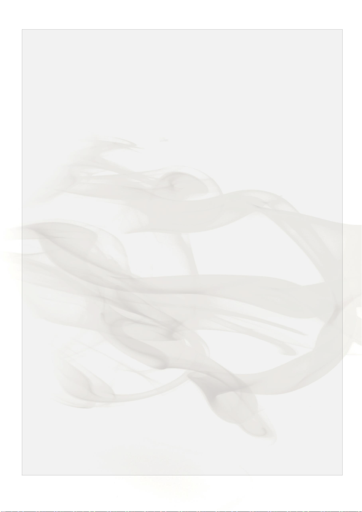
To take the appliance out of the packaging, proceed as Pic. 1:
1. Turn the fan coil box upside down and open the bottom.
2. Remove the polystyrene filling and keep it.
3. Keeping the bottom of the box open, turn the pack 180°, taking care that the contents are firmly hold
before resting it gently on the ground. Lift off the packaging from the appliance.
SAFETY RULES
Secure packs during transportation.
Do not expose to the elements.
Do not tread on packs.
Protect hands with work gloves when dismantling
the appliance.
Work in PAIRS if the applinance weighs more than
25 kg.
IOM_FCW-FCCW_10a120_207995_181001_EN
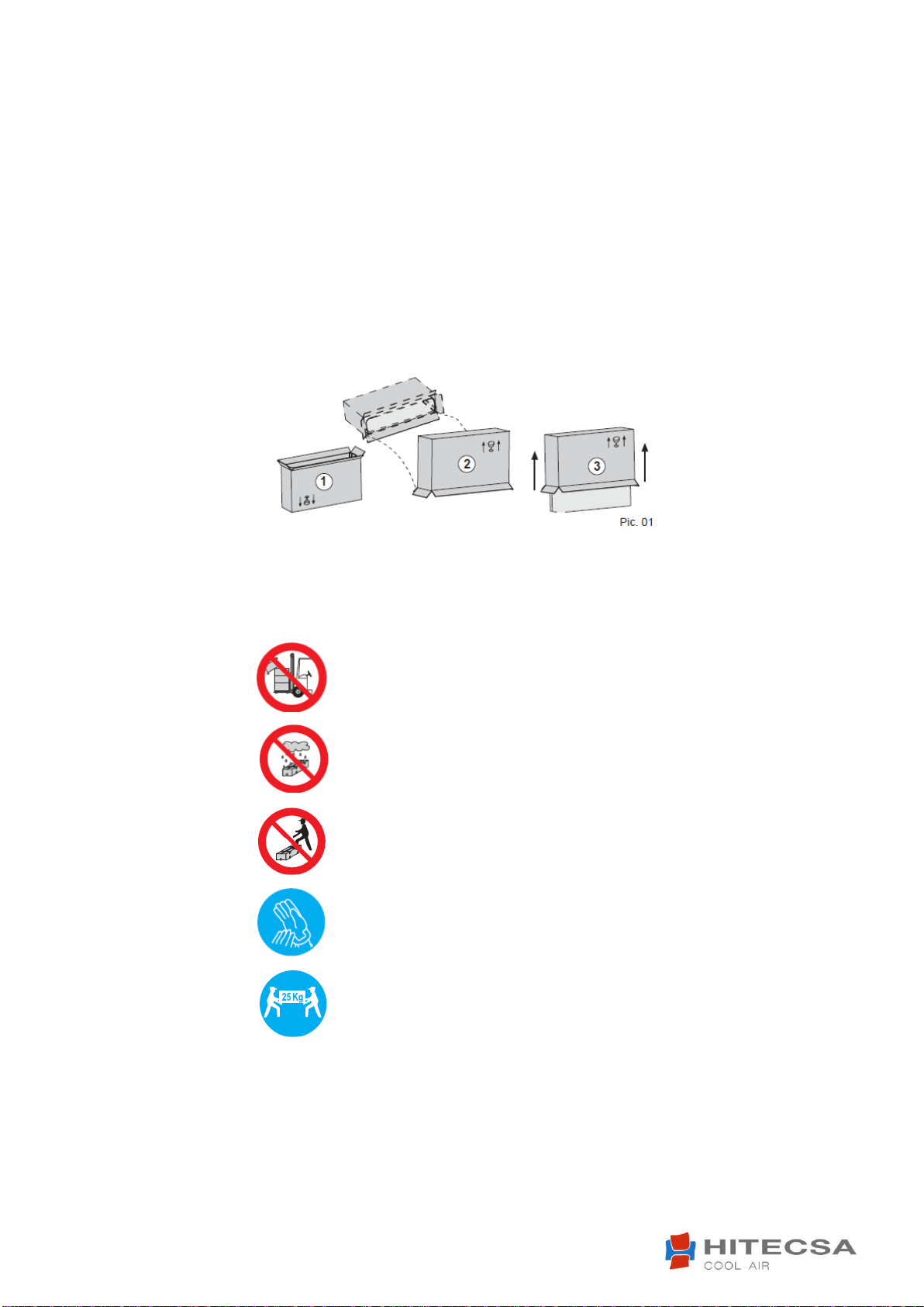
GENERAL DIMENSIONS
* NOTE: dimensions referred to the units with left side water connections
GENERAL TECHNICAL DATA

IOM_FCW-FCCW_10a120_207995_181001_EN
MAIN PARTS
RECOMMENDATIONS FOR INSTALLATION
Before installing the appliance, ensure that:
1) The place of installation has sufficient space for carrying out installation as well as routine and
extraordinary maintenance work (see Pic. 4).
2) There are no obstructions for air intake and delivery.
3) The water connections are of the sizes, in the position and spaced apart as required by the appliance
(see Dimension).
4) The system pressure does not exceed 8 bar for the water versions.
5) The electricity supply corresponds to the data on the appliance rating plate and that there is a safety
switch readily accessible to the user to cut off the power supply whenever necessary.
6) The safety switch is in the OFF position so that there is no voltage on the appliance supply line.
IOM_FCW-FCCW_10a120_207995_181001_EN
FAN COIL INSTALLATION
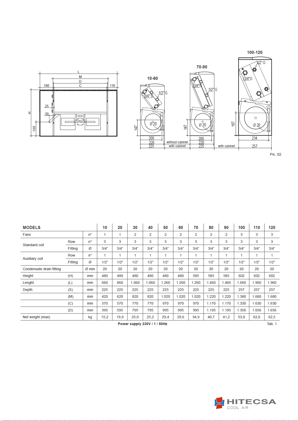
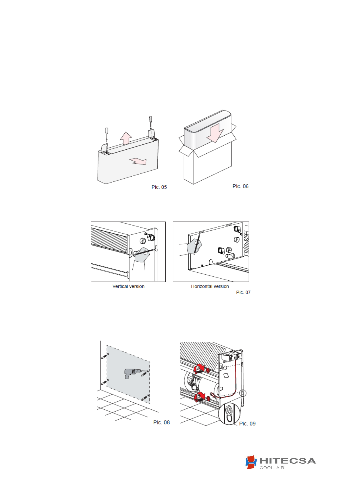
Before installing the appliance, remove the housing (if present). Raise the flaps covering the control panel
and the water connections. Remove the two screws fixing the housing to the fan coil load-bearing
structure. Gipping the rear of the housing, remove it as shown in the Pic. 5 (NOTE: be careful of the lugs
on the front part of the load-bearing structure, as shown in Pic.10).
Put the cabinet in the packing box to prevent it from being soiled or damaged (Pic.6)
Offer the appliance up to the required point of installation and mark, through the fixing holes, the points on
the wall where the holes should be driller for the 4 screw anchors, as shown in Pic. 7.
Remove the appliance from the point of installation; drill the holes where marked on the wall (see Pic. 8)
and insert the screw anchors. Place the appliance against the wall and fix it by tightening the screws into
the anchors see (Pic.9). Carry out the water and electrical connections as described in the relevant
paragraphs.
IOM_FCW-FCCW_10a120_207995_181001_EN
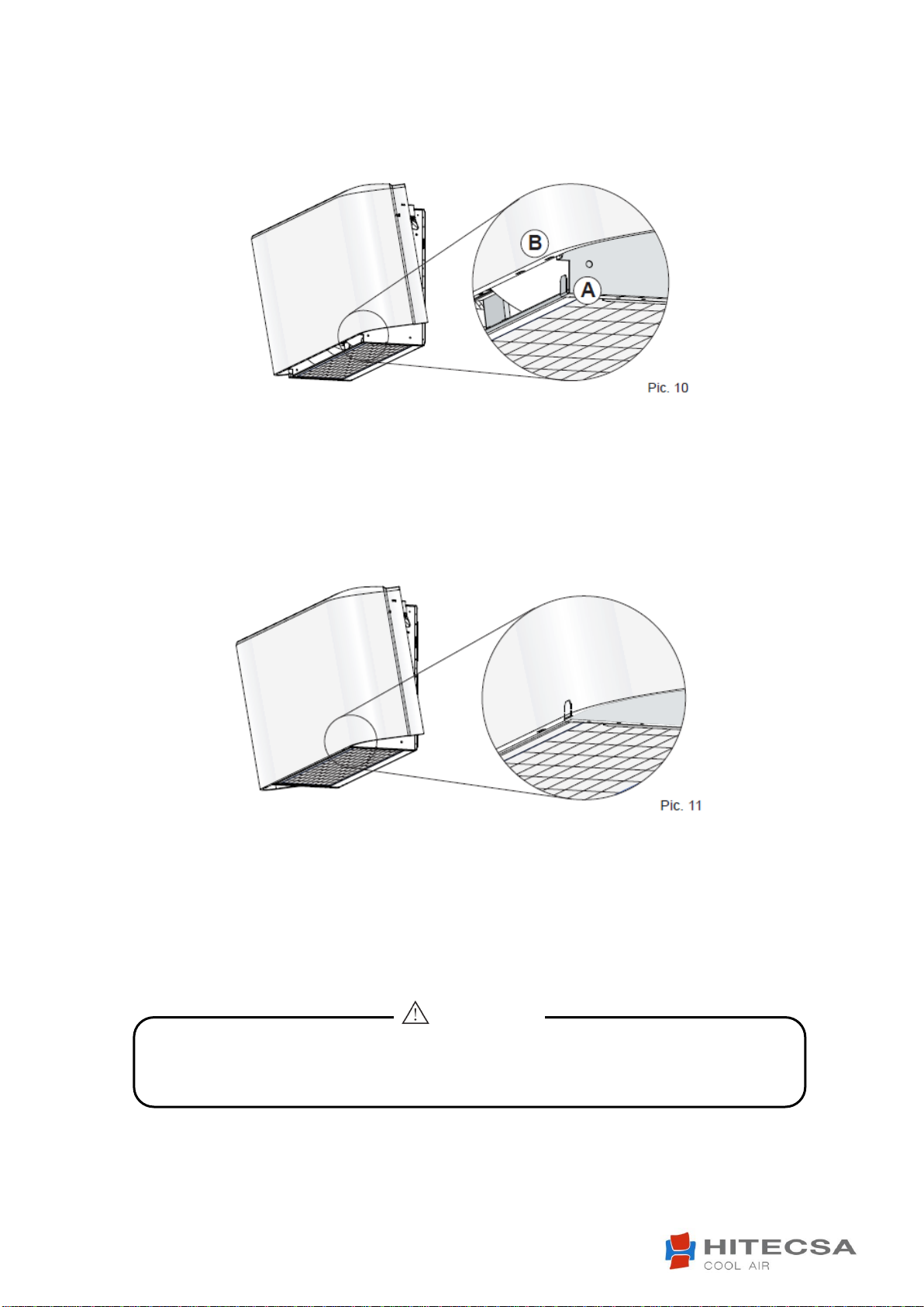
To replace the housing.
Take the cabinet from the packing box. Standing in front of the fancoil, lift cabinet, holding it by the sides,
and tilt it (Pic. 10).
Insert the lugs A into the relative slots B (Pic.11). Pivot the cabinet on its base until it is aligned with the
wall. Raise the flaps covering the control panel and water connections and tighten the two fixing screws
(Pic.5).
Fan coil units have the following operating limits:
- it can't be installed in areas with anomalous heat and humidity conditions
- it can't be installed outdoors
- it can't be installed in explosive environments
- it can't be installed in a corrosive atmosphere
WATER CONNECTIONS
CONNECTION TO THE WATER MAINS
Always use a wrench and nose key for connection of the coil
to the pipes (Pic. 12). If the solenoid valve is installed, suitably insulate the valve body with
insulating material (Pic. 13).
ATENTION!

IOM_FCW-FCCW_10a120_207995_181001_EN
Connect the water inlet and outlet pipes, observing the indications given on the side of the appliance.
Correctly insulate the water supply pipes to prevent dripping during the cooling mode of operation. A
shutoff valve should be inserted on the water supply pipe and balancing valve on the outlet pipe. The valve
body and balancing valve should also be properly insulated to prevent dripping. It is the installer’s
responsibility to insulate properly and the manufacturer cannot be held liable for any insulation work.
NOTE:
It is always advisable to install the solenoid valve. In the heating mode of operation the solenoid
valve reduces consumption because upon reaching the set temperature the circulation of water is
stopped to avoid wasting energy (the fan coil would otherwise continue to heat like a radiator, even
with the motor at a standstill). In the cooling mode of operation the solenoid valve stops the
circulation of water when the set temperature is reached, this stopping the internal exchanger from
continuing to condense water with possible undesirable dripping into the floor. It also reduces
chiller operation with consequent energy savings.
CONDENSATE WATER DRAINGE
The condensate drain pipe should slope downwards by at least 3 cm/m and should not have ascending or
throttled section in order to ensure a regular flow of water. It is advisable for a trap to be fitted. The
condensate drain pipe should be connected to a rainwater drainage system. Do not use sewage system to
avoid possible smells in the event of evaporation of the water in the trap. Upon completion of work, check
that the condensate flows out properly by pouring water into the tray (see Pic. 14 and 15). The condensate
water drainage system should be fabricated in a workmanlike manner and should be periodically checked.
The manufacturer cannot be held liable for any damage caused by dripping in the absence of a solenoid
valve or of periodic maintenance of the drainage system.
IOM_FCW-FCCW_10a120_207995_181001_EN
Failure to comply with the indicated connections may cause motor burnout!
ATTENTION!
ELECTRICAL CONNECTIONS
Before carrying out electrical connections, ensure that the electricity supply to the supply line has been cut
off, checking that the on-off switch is in the OFF position. Only qualified electricians should carry out the
electrical connections.
Check that the mains supply is single-phase 230 Vac/1/50 Hz (± 10%).
Operating the appliance with voltages outside the above limits could cause malfunction and renders the
warranty null and void.
The fan coil power supply line should be fitted with at least a switch isolator in conformity with European
standard EN60947-3. Make sure that the electrical system is suitable for providing not only the working
current required by the appliance, but also the necessary current for powering household and other
electrical appliances already in use.
Any electrical and mechanical alterations or tampering render the warranty null and void. The motor and
accessories power cables in channels or ducts should remain inside the same until they are inside the
appliances.
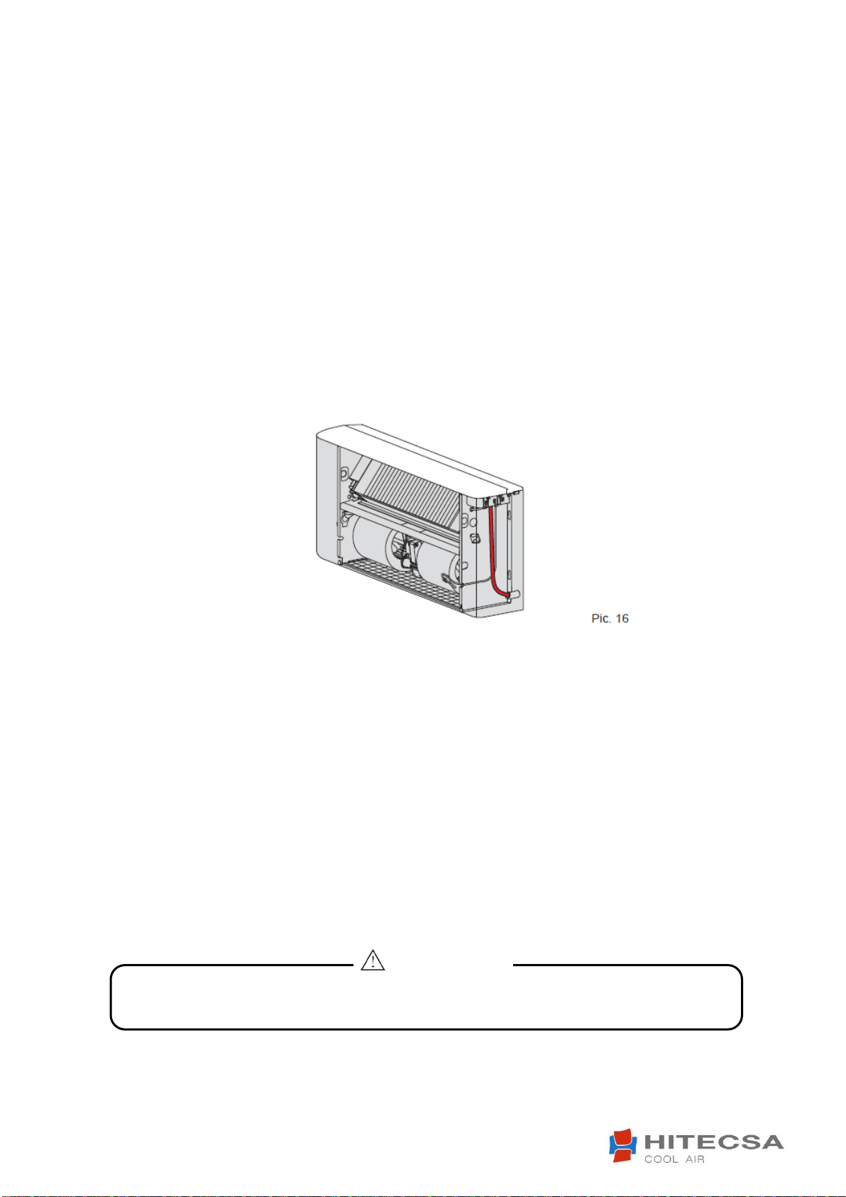
The cables should be sufficiently long so that they are not permanently taut or create throttling or pressure
on metal parts (see Pic. 16). The power cables should be sufficiently long so that in the event of accidental
tugging the active wires are subjected to stress before the earth wire. Connect the earth wire to the relative
terminal marked with the symbol.
Check the earth connection. Comply with the safety regulations in force in the country of installation.
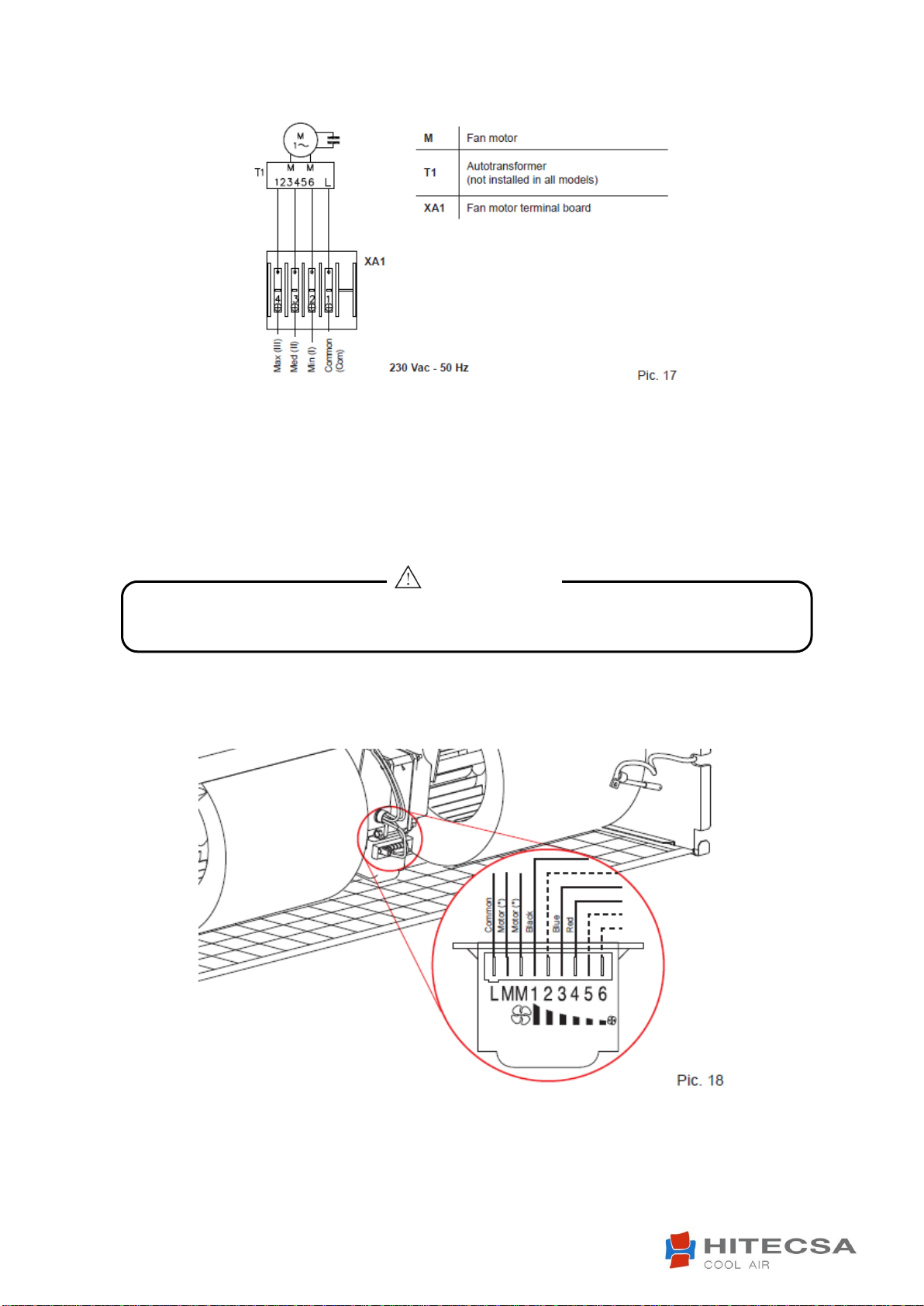
CONNECTIONS TO THE TERMINAL BLOCKS
WITHOUT CONTROL PANEL
The electrical connections should be made to the terminal block on the side of the appliance
(Pic. 17). Each terminal is identified by the label to be found on the terminal block.
WITH CONTROL PANEL
The electrical connections should be made directly to the control panel, as shown by the relative
wiring diagram. If the control panel has an electronic temperature sensor (NTC) this sensor will
be powered by mains voltage (230Vac/1/50 Hz) and is therefore provided with double
insulation.
IOM_FCW-FCCW_10a120_207995_181001_EN
Under no circumstances should the connections to the terminals L, M, M be changed!
ATTENTION!
CHANGING THE MOTOR SPEEDS OF ROTATION
The fan coil motor has 6 speed settings, 3 of which are connected in the factory (red, blue and black wires
connected to the motor auto-transformer). To use other speeds than those wired up in the factory, the red
(minimum), blue (medium) and black (maximum) wires may be connected onto 3 of the 6 numbered
terminals (1…6), taking into account that the speeds follow a sequence as shown in Pic. 18.

IOM_FCW-FCCW_10a120_207995_181001_EN
Protect the appliance with a cardboard box if building works are still being carried out (Pic. 19).
ATTENTION!
TESTING THE FANCOIL
Upon completion of installation, scrupulously check both the water and the electrical connections before
switching on the appliance.
Before mounting the housing (if present), fill the system, bring it up to pressure and bleed. Make the
water circulate and check for leaks.
Check correct operation of the fan coil at the 3 speeds, of the solenoid valves and of the minimum
temperature thermostat (if installed). The cabinet is covered by a protective film: remove it before
fixing the housing to the appliance.
Remount the housing (if present), otherwise the customer has the responsibility of concealing the
appliance.
TURNING THE COIL
The fan may reach the speed of 1,000 rpm. Do not insert objects or hands into the electric fan. The motor
becomes hot during operation; wait for it to cool before touching it. During the heating mode of operation
the exchanger and the connecting pipes may become very hot (80°C).
Wait for the exchanger to cool before touching it or protect hands with suitable gloves. The heat
exchange water coils are suitable for working up to maximum pressure of 8 bar. To turn the coil,
proceed as follows:
1. Remove the housing (if present).
2. Disconnect the terminal block or the control panel (2), if present, from the side of the appliance.
3. Remove the condensate collecting tray in horizontal models or the galvanized panels in vertical models
(4).
4. Remove the coil fixing screws (5).
5. Take out the coil (1), being careful not to be cut by the fi ns and not to damage them.
6. Remove the knockouts (6) on the opposite side of the fan coil (using a screwdriver), to allow the coil
connections to pass through.
7. Position the coil, turning it without tipping it upside down, so that the fittings are in line with the holes left
by the knockouts.
8. Fix the coil using the previously removed screws (5).
9. Shift the control panel (2), if present, or the terminal block (fixing it to the side opposite the water
fittings), the motor and sensor cables (3), if present, fixing them with their grips. Ensure that the cables
pass through the hole in the side of the appliance, protecting them with the relative grommet. If it proves
easier to carry out this operation by separating the wires from the terminal blocks, mark the positions of the
wires to avoid making mistakes when reconnecting.

IOM_FCW-FCCW_10a120_207995_181001_EN
10. Reconnect the wires to the relative terminal blocks or control panel (2), taking care that they are
correctly positioned.
11. Replace the condensate collecting tray (4) in horizontal models or the galvanized panels in vertical
models.
12. Remount the housing (if present).
USING THE APPLIANCE
This appliance should only be used by adults. Make sure that children do not touch the controls or play
with the appliance. This appliance has been designed for use as a heating and cooling appliance in rooms
that are clean and frequented by persons (with normal pollution). Avoid using for any other purpose. This
appliance should not be used in places with suspended dust/powder or in potentially explosive
atmospheres, in very damp environments or in the presence of oil in suspension or in particularly
aggressive atmospheres.
IOM_FCW-FCCW_10a120_207995_181001_EN
USING THE CONTROL PANEL
If the appliance has a built-in control panel, raise the flap and proceed as follows.
Heating mode
Put the season selector switch from the off position ( ) to the winter position ( ). The fan starts.
In models with minimum temperature thermostat (optional), the fan starts when the internal heat
exchanger is sufficiently hot. If the water is not hot enough, the fan does not start.
Cooling mode
Put the season selector switch from the off position ( ) to the summer position ( ). The fan starts
immediately.
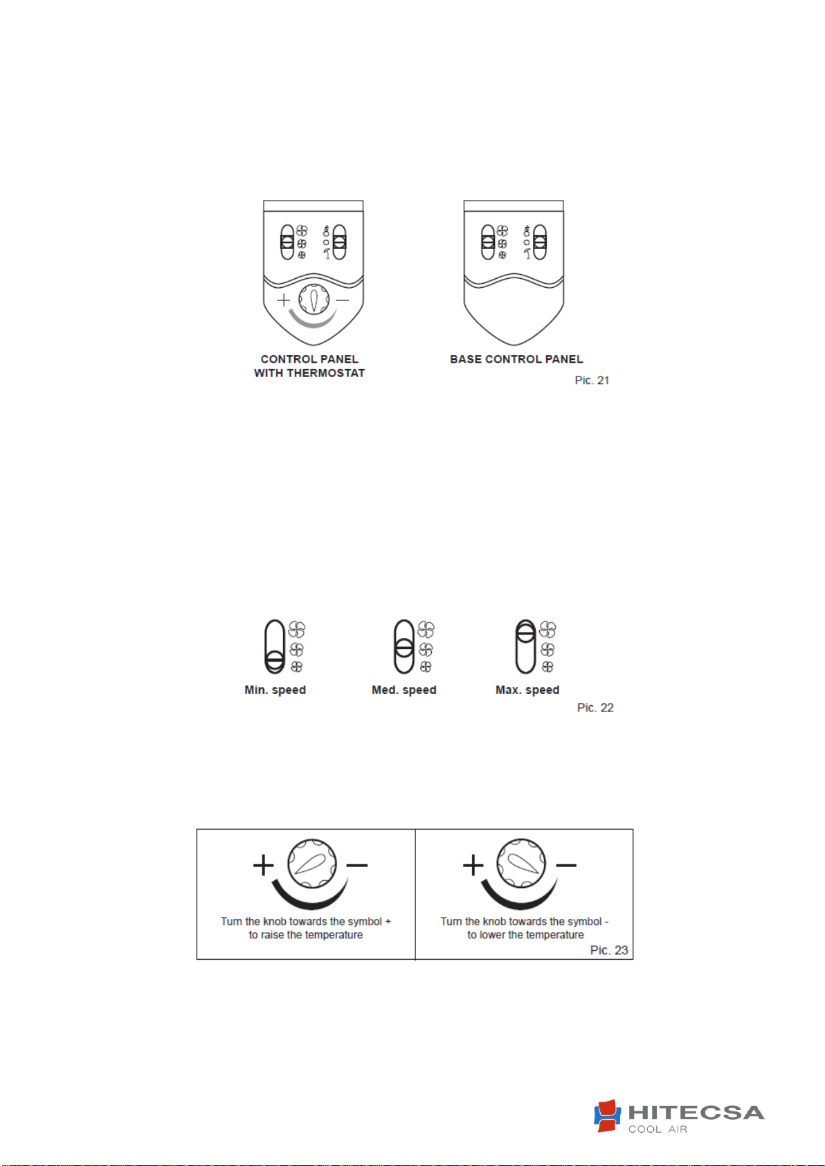
Selecting the fan speed
Put the selector switch to the required speed. The higher the speed the quicker the room will be
heated/cooled, although appliance operation will be noisier (Pic. 22).
Automatic temperature adjustment (for control panel with built-in thermostat)
This control panel has a built-in temperature sensor, which measures the room air temperature. This
information is used for the automatic control of the fan or introduction of water into the internal exchanger
through the solenoid valve (optional).
The appliance this keeps the room at the temperature set by the user.
The room temperature may be set approx. between 10°C and 30°C. If the appliance does not have a
built-in control panel, but is controlled by a wall-mounted thermostat, refer to the thermostat
instructions for use.

IOM_FCW-FCCW_10a120_207995_181001_EN
Before carrying out any cleaning or maintenance work, disconnect the appliance from the mains
electricity supply!
ATTENTION!
CLEANING AND MAINTENANCE
The appliance requires no periodic maintenance. Simple checks by the user to keep it in perfect working
order are, however, necessary.
CLEANING THE AIR FILTER
The appliance is fitted with an air filter on the fan inlet. During normal operation the filter withholds
impurities in the air. The filter should be cleaned periodically to keep its filtering properties and the airflow
to the fan unchanged. It is advisable to clean the filter at least once a month, proceeding as follows.
1. Take out the filter.
2. Place the filter on a flat, dry surface and remove the accumulated dust with a vacuum cleaner.
3. Wash the filter with water and detergent (no solvents).
4. Leave the filter to dry in a ventilated place in the sun.
5. Replace the filter when it is perfectly dry.
Clean the filter at the beginning and end of every season
Description Pic. 24 - Cleaning the fi lter for the lower intake version
Description Pic. 25: Cleaning the fi lter for the front intake version
NOTE
The procedure for ceiling-mounted horizontal version is the same.

IOM_FCW-FCCW_10a120_207995_181001_EN
CLEANING THE HOUSING AND THE CONTROL PANEL
To clean the housing, use a dry soft cloth to avoid scratching the enamel.
To clean the control panel and the air outlet louvers, use a vacuum cleaner fitted with a soft dusting tool or
use a separate brush.
Delicately clean the louvers and the controls by removing dust from the cracks and corners.
Under no circumstances use water.
WHAT TO DO IF…

IOM_FCW-FCCW_10a120_207995_181001_EN
HIPLUS AIRE
ACONDICIONADO S.L.
Masia Torrents, 2
Tel. +34 93 893 49 12
Fax. +34 93 893 96 15
08800 Vilanova i la Geltrú
Barcelona, España
www.hitecsa.com
We reserve the right to make modifications without prior notice
This manual suits for next models
25
Table of contents
Other Hitecsa Fan manuals


