Hiwin D1NCOE User manual

Drive User Guide
1
Version 1.0
Mar 2014
www.servosystem.ru +7(495) 407-01-02

Drive User Guide
2
Contexts
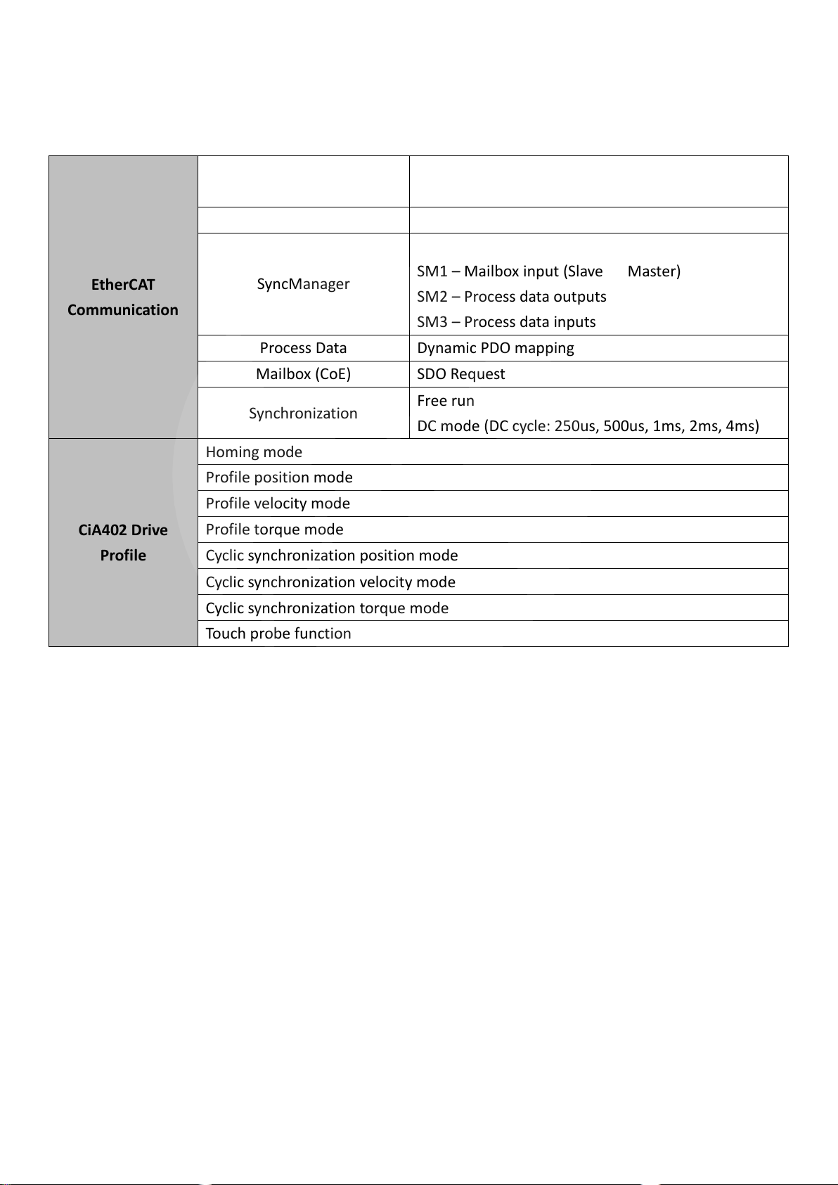
1. Communication Specification of EtherCAT ............................................................................................4
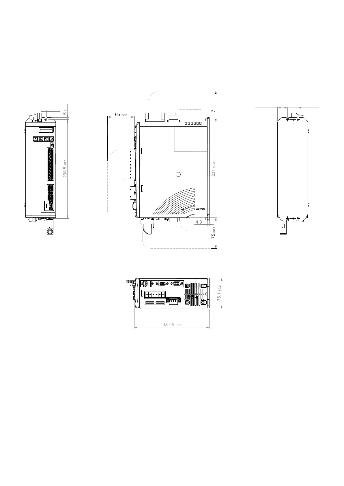
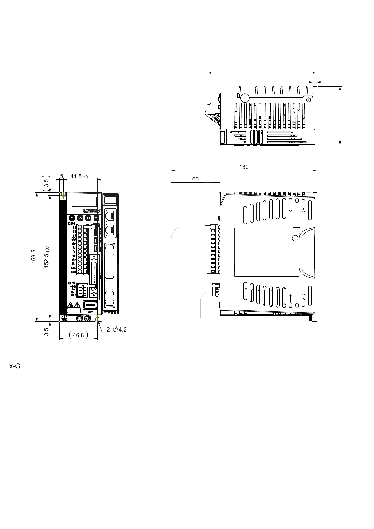
2. Physical Dimensions...............................................................................................................................5
3. Object Dictionary Table..........................................................................................................................8
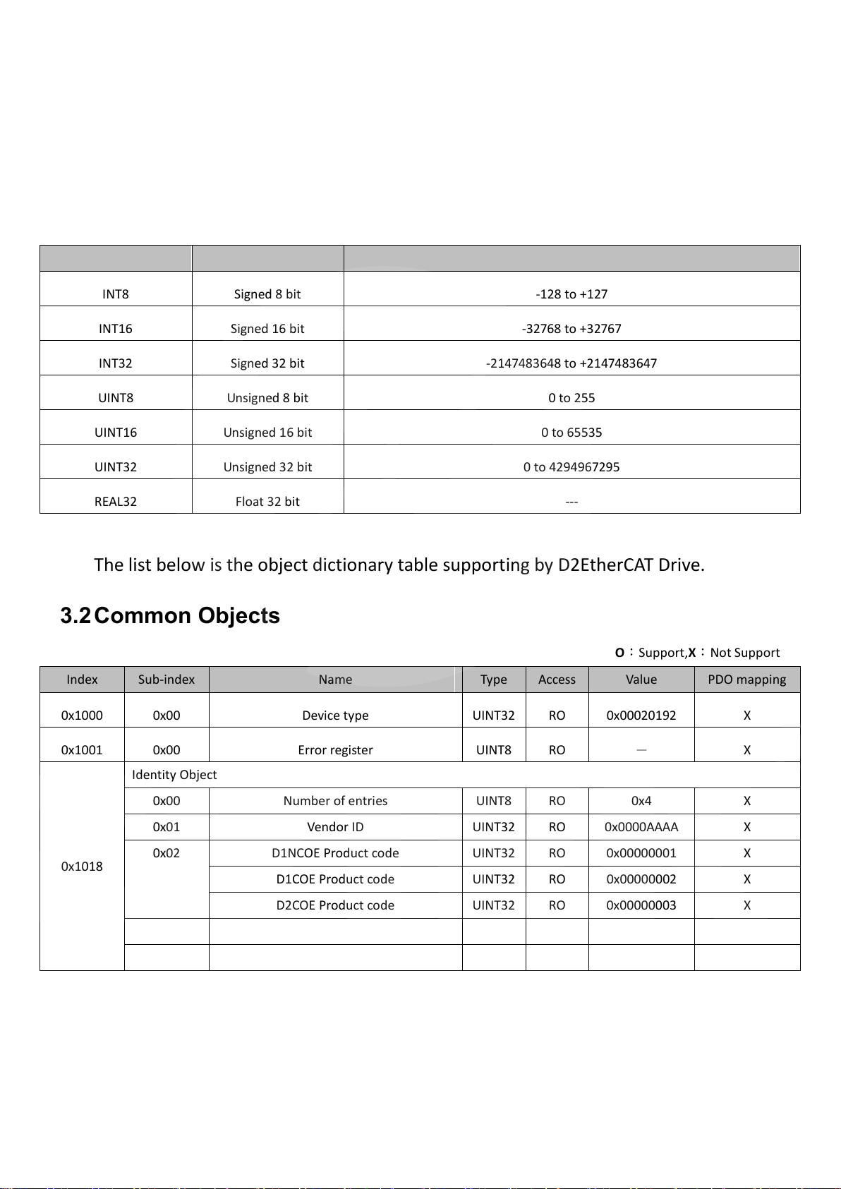
3.1 Data Type ...................................................................................................................................8
3.2 Common Objects .......................................................................................................................8
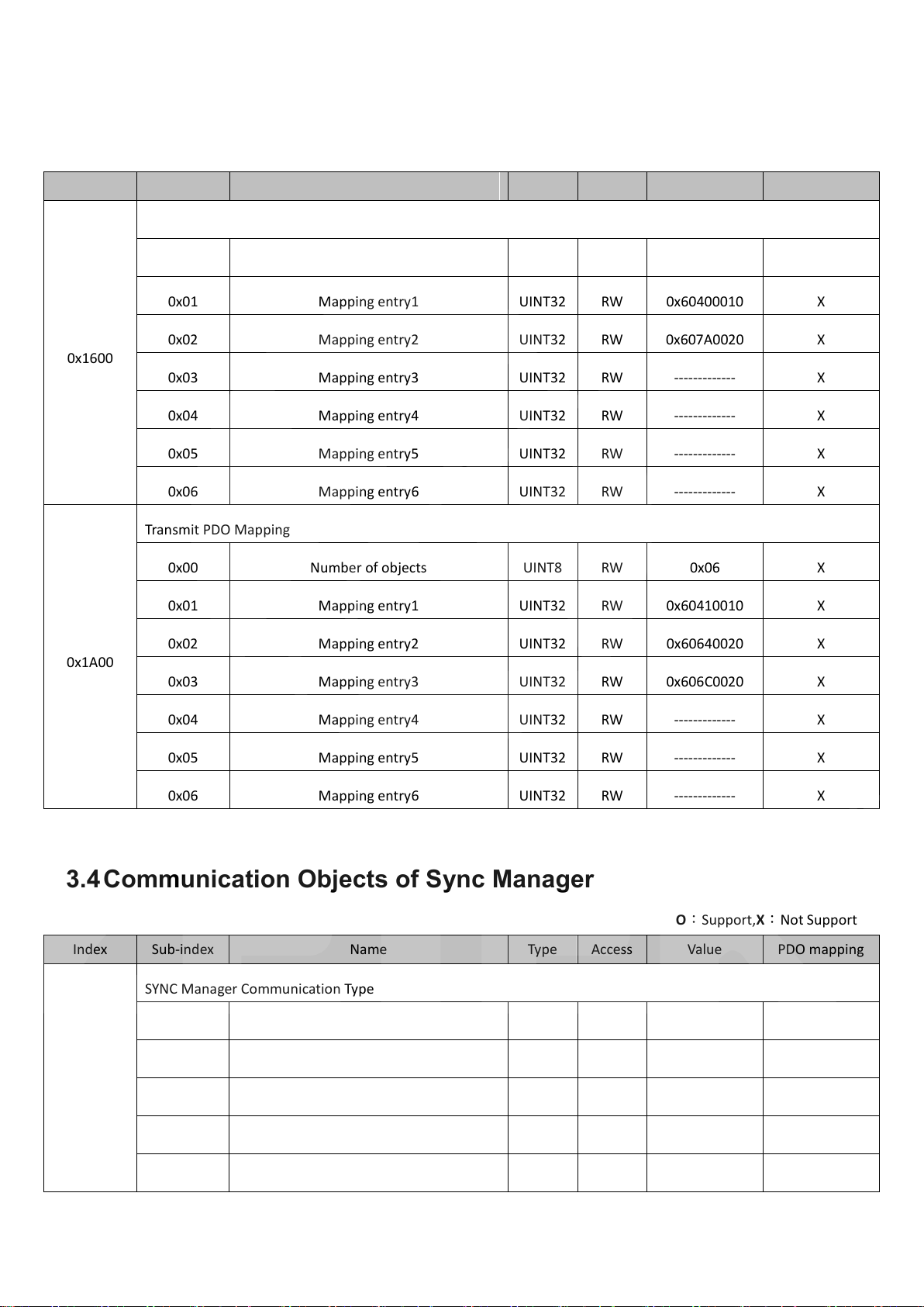
3.3 PDO Mapping Objects................................................................................................................9
3.4 Communication Objects of Sync Manager ................................................................................9
3.5 CiA 402 Objects of Guide Regulations .....................................................................................10
3.6 Manufacturer Defined Objects ................................................................................................12
3.7 Objects description of the Manufacture Defined Objects.......................................................12
4. Communication Architecture of EtherCAT Drive .................................................................................15
5. State Machine of EtherCAT ..................................................................................................................17
6. State Machine of CiA402 .....................................................................................................................19
7. PDO Mapping.......................................................................................................................................21
8. Synchronization Mode.........................................................................................................................23
9. Drive’s Mode of Operation ..................................................................................................................24
9.1 Position Control Mode.............................................................................................................24
9.1.1 Profile Position Mode (PP)...........................................................................................24
9.1.2 Cyclic Synchronization Position Mode .........................................................................28
9.2 Velocity Control Mode .............................................................................................................30
9.3 Torque Control Mode...............................................................................................................32
9.4 Homing Mode ..........................................................................................................................33
10. Touch Probe Function ..................................................................................................................41
A. How to use TwinCAT making connection with drive ...........................................................................43
B. How to use TwinCAT operating drive in position mode ......................................................................46
C. How to use TwinCAT to process dynamic PDO Mapping.....................................................................52
D. How to setup the Operational Mode for EtherCAT .............................................................................53
www.servosystem.ru +7(495) 407-01-02

Drive User Guide
3
Revision History
Release
Date
Applies to
Notice
1.0
2014.03.17
D-series CoE Drive
First Release
www.servosystem.ru +7(495) 407-01-02

Drive User Guide
4
1. Communication Specification of EtherCAT
EtherCAT
Communication
Communication Standards
IEC 61158 Type 12
IEC 61800-7 CiA402 Drive Profile
Physical Layer
100BASE-TX (IEEE802.3)
SyncManager
SM0 –Mailbox output (Master Slave)
SM1 –Mailbox input (Slave Master)
SM2 –Process data outputs
SM3 –Process data inputs
Process Data
Dynamic PDO mapping
Mailbox (CoE)
SDO Request
Synchronization
Free run
DC mode (DC cycle: 250us, 500us, 1ms, 2ms, 4ms)
CiA402 Drive
Profile
Homing mode
Profile position mode
Profile velocity mode
Profile torque mode
Cyclic synchronization position mode
Cyclic synchronization velocity mode
Cyclic synchronization torque mode
Touch probe function
www.servosystem.ru +7(495) 407-01-02

Drive User Guide
5
2. Physical Dimensions
D1NCOE drive
5±0.1
238.5 ±0.1
4.2
4.9
231 ±0.2
75 ±0.5 75 ±0.5
65 ±0.5
75.1 ±0.2
181.6 ±0.2
25 ±0.1
24.15 ±0.1
www.servosystem.ru +7(495) 407-01-02

Drive User Guide
6
D1COE drive
www.servosystem.ru +7(495) 407-01-02

Drive User Guide
7
D2COE drive
46.8
5±0.1
3.53.5 152.5 ±0.1
2- 4.2
159.5
60
180
72.8
135.5
5
D2-04xx-E(F)-Bx-G
Date:20140127
1 2 3 54 976 8
G
F
D
E
B
C
A
www.servosystem.ru +7(495) 407-01-02

Drive User Guide
8
3. Object Dictionary Table
This table lists the data types and range used in this manual and drive.
3.1 Data Type
Code
Data Type
Range
INT8
Signed 8 bit
-128 to +127
INT16
Signed 16 bit
-32768 to +32767
INT32
Signed 32 bit
-2147483648 to +2147483647
UINT8
Unsigned 8 bit
0 to 255
UINT16
Unsigned 16 bit
0 to 65535
UINT32
Unsigned 32 bit
0 to 4294967295
REAL32
Float 32 bit
---
The list below is the object dictionary table supporting by D2EtherCAT Drive.
3.2 Common Objects
O:Support,X:Not Support
Index
Sub-index
Name
Type
Access
Value
PDO mapping
0x1000
0x00
Device type
UINT32
RO
0x00020192
X
0x1001
0x00
Error register
UINT8
RO
-
X
0x1018
Identity Object
0x00
Number of entries
UINT8
RO
0x4
X
0x01
Vendor ID
UINT32
RO
0x0000AAAA
X
0x02
D1NCOE Product code
UINT32
RO
0x00000001
X
D1COE Product code
UINT32
RO
0x00000002
X
D2COE Product code
UINT32
RO
0x00000003
X
0x03
Revision number
UINT32
RO
0x00000000
X
0x04
Serial number
UINT32
RO
0x00000000
X
www.servosystem.ru +7(495) 407-01-02

Drive User Guide
9
3.3 PDO Mapping Objects
O:Support,X:Not Support
Index
Sub-index
Name
Type
Access
Value
PDO mapping
0x1600
Receive PDO Mapping
0x00
Number of objects
UINT8
RW
0x06
X
0x01
Mapping entry1
UINT32
RW
0x60400010
X
0x02
Mapping entry2
UINT32
RW
0x607A0020
X
0x03
Mapping entry3
UINT32
RW
-------------
X
0x04
Mapping entry4
UINT32
RW
-------------
X
0x05
Mapping entry5
UINT32
RW
-------------
X
0x06
Mapping entry6
UINT32
RW
-------------
X
0x1A00
Transmit PDO Mapping
0x00
Number of objects
UINT8
RW
0x06
X
0x01
Mapping entry1
UINT32
RW
0x60410010
X
0x02
Mapping entry2
UINT32
RW
0x60640020
X
0x03
Mapping entry3
UINT32
RW
0x606C0020
X
0x04
Mapping entry4
UINT32
RW
-------------
X
0x05
Mapping entry5
UINT32
RW
-------------
X
0x06
Mapping entry6
UINT32
RW
-------------
X
3.4 Communication Objects of Sync Manager
O:Support,X:Not Support
Index
Sub-index
Name
Type
Access
Value
PDO mapping
0x1C00
SYNC Manager Communication Type
0x00
Number of used sync manager
UINT8
RO
0x04
X
0x01
Sync manager0
UINT8
RO
0x01
X
0x02
Sync manager1
UINT8
RO
0x02
X
0x03
Sync manager2
UINT8
RO
0x03
X
0x04
Sync manager3
UINT8
RO
0x04
X
www.servosystem.ru +7(495) 407-01-02

Drive User Guide
10
0x1C12
SYNC Manager PDO Assignment 2
0x00
Number of assigned RxPDOs
UINT8
RW
0x01
X
0x01
Assigned RxPDO mapping object1
UINT16
RW
0x1600
X
0x1C13
SYNC Manager PDO Assignment 3
0x00
Number of assigned TxPDOs
UINT8
RW
0x01
X
0x01
Assigned TxPDO mapping object1
UINT16
RW
0x1A00
X
3.5 CiA 402 Objects of Guide Regulations
O:Support,X:Not Support
Index
Sub-index
Name
Type
Access
Value
PDO mapping
0x6040
0x00
ControlWord
UINT16
RW
-
O
0x6041
0x00
StatusWord
UINT16
RO
-
O
0x6060
0x00
Mode of operation
INT8
RW
-
O
0x6061
0x00
Mode of operation display
INT8
RO
-
O
0x6063
0x00
Position Actual Internal Value
INT32
RO
-
O
0x6064
0x00
Position Actual Value
INT32
RO
-
O
0x6065
0x00
Following Error Window
UINT32
RW
-
X
0x606C
0x00
Velocity Actual Value
INT32
RO
-
O
0x6071
0x00
Target Torque
INT16
RW
-1000~1000
O
0x6075
0x00
Continuous Current of Motor (mA)
UINT32
RW
-
X
0x6078
0x00
Current Feedback of Motor (0.1%)
INT16
RO
-
O
0x607A
0x00
Target Position
INT32
RW
-
O
0x607C
0x00
Home offset
INT32
RW
-
X
0x607D
Software Position Limit
0x00
Number of entries
UINT8
RO
0x2
X
0x01
Minimum Position Limit
INT32
RW
-
X
0x02
Maximum Position Limit
INT32
RW
-
X
0x607F
0x00
Maximum Profile Velocity
UINT32
RW
-
X
www.servosystem.ru +7(495) 407-01-02

Drive User Guide
11
Index
Sub-index
Name
Type
Access
Value
PDO mapping
0x6081
0x00
Profile Velocity
UINT32
RW
-
X
0x6083
0x00
Profile Acceleration
UINT32
RW
-
X
0x6084
0x00
Profile Deceleration
UINT32
RW
-
X
0x6085
0x00
Quick Stop Deceleration
UINT32
RW
-
O
0x6087
0x00
Torque Slope
UINT32
RW
-
O
0x6098
0x00
Homing Method
UINT16
RW
-
X
0x6099
Homing Speeds
0x00
Number of entries
UINT8
RD
0x02
X
0x01
Speed during search for switch
UINT32
RW
-
X
0x02
Speed during search for zero
UINT32
RW
-
X
0x609A
0x00
Homing Acceleration
UINT32
RW
1000000
X
0x60B1
0x00
Velocity Offset
INT32
RW
-1000~1000
O
0x60B2
0x00
Torque Offset
INT16
RW
-1000~1000
O
0x60B8
0x00
Touch Probe Function
UINT16
RW
-
O
0x60B9
0x00
Touch Probe Status
INT32
RO
-
O
0x60BA
0x00
Touch Probe 1 Position Value
INT32
RO
-
O
0x60C2
Interpolation Time Period
0x00
Highest sub-index supported
INT8
RO
1
X
0x01
Interpolation time period
UINT16
RW
8
X
0x60F4
0x00
Following Error Actual Value
INT32
RD
-
O
0x60FC
0x00
Position Demand Internal Value
INT32
RO
-
O
0x60FD
0x00
Digital Inputs
UINT32
RO
-
O
0x60FF
0x00
Target Velocity
UINT32
RW
-
O
0x6502
0x00
Supported Drive Mode
UINT32
RO
0x3AF
X
www.servosystem.ru +7(495) 407-01-02

Drive User Guide
12
3.6 Manufacturer Defined Objects
O:Support, X:Not Support
Index
Sub-index
Name
Type
Access
Default Value
PDO mapping
0x2000
0x00
Motor type
UINT16
RO
-
X
0x2001
0x00
Encoder Resolution of Velocity Loop
INT32
RO
-
X
0x2002
0x00
Encoder Resolution of Position Loop
INT32
RO
-
X
0x2003
0x00
Screw Pitch
INT32
RO
-
X
0x2010
0x00
Input Function
UINT16
RW
0x0
O
0x2020
0x00
Index Signal
INT8
RO
-
X
0x2021
0x00
Latched Index Position
INT32
RO
-
O
0x2022
0x00
Motor actual current
REAL32
RO
-
O
0x2040
0x00
Use the 2nd linear digital encoder
UINT16
RO
-
X
0x2041
0x00
Enable software position limit protection
UINT16
RW
0x01
X
0x2042
0x00
Enable hardware limit protection
UINT16
RW
0x01
X
0x2050
0x00
Common gain (CG:0.01~1.0)
REAL32
RW
0.3
X
0x2051
0x00
Velocity proportional gain
REAL32
RW
0.001
X
0x2060
0X00
Multi turn encoder reset flag
UINT8
RW
0
X
0x2100
0x00
Drive Error Events 1
UINT32
RO
0
X
0x2101
0x00
Drive Error Events 2
UINT32
RO
0
X
3.7 Objects description of the Manufacture Defined Objects
0x2000 - Motor type
0: Linear motor
1: Torque motor
2: AC servo motor
0x2001 - Encoder resolution of velocity loop
The encoder resolution is the rotary encoder resolution.
0x2002 - Encoder resolution of position loop
The encoder resolution is the linear scale resolution. (The AC servo motor with ball screw)
0x2003 - Screw pitch
The value is corresponded to the ball screw user using.
www.servosystem.ru +7(495) 407-01-02

Drive User Guide
13
0x2010 - Input function
bit0 - Activate error mapping
bit1 - Reset the drive.
0x2020 –Index signal
The object is used to home procedures by host controller.
0: No Index.
1: Index is touched.
0x2021 –Latch Index position
This object is for user checking the repeatability of home position.
0x2022 –Motor actual current
This object is used to display Ampere unit of the current value.
0x2040 –Use the 2nd linear digital encoder
0: Not use the 2nd linear digital encoder
1: Use the 2nd linear digital encoder
0x2041 –Enable software position limit protection
0: Disable the software position limit protection
1: Enable the software position limit protection
0x2042 –Enable hardware position limit protection
0: Disable the hardware position limit protection
1: Enable the hardware position limit protection
0x2050 –Common gain
This object is for user to tune the motor performance (stiffness) in all servo loop.
0x2051 –Velocity proportional gain
This object is for user to tune the motor performance (stiffness) in velocity loop .
0x2051 –Velocity proportional gain
This object is for user to tune the motor performance (stiffness) in velocity loop .
0x2060 –Multi turn encoder reset flag
This object is used only for the multi turn encoder.
0: Nothing happen.
0->1: Set the multi turn encoder position to zero.
0->2: Clear the multi turn encoder error.
0x2100 –Drive Error Events 1
Bit 1: Encoder error
Bit 6: Position error too big
Bit 7: Soft-thermal threshold reached
Bit 13: Serial encoder communication error
Bit 14: Motor over temperature sensor activated
Bit 15: Amplifier over temperature
Bit 18: Motor short (over current) detected
www.servosystem.ru +7(495) 407-01-02

Drive User Guide
14
Bit 19: Over voltage detected
Bit 20: Under voltage detected
Bit 21: Motor maybe disconnected
Bit 18: Motor short (over current) detected
Bit 31: 5V for encoder card fail
Others: reserved.
0x2101–Drive Error Events 2
Bit 1: Phase initialization error
Bit 5: Hall sensor error
Bit 6: Hall phase check error
Others: reserved
www.servosystem.ru +7(495) 407-01-02

Drive User Guide
15
4. Communication Architecture of EtherCAT Drive
The figure shown below indicates the architecture of CoE(CANopen over EtherCAT) drive network
module. It can be separated to data link layer and application layer. Data link layer is used to manage the
transmission interface of data between the master and salve station. Application layer is used to
implement the function of state transition compatible between CiA402 (CANopen Drive Communication
Protocol) and EtherCAT.
There are two types of data transition mode between the application layer and data link layer: time
critical and non-time-critical data transition. Data of time critical indicates that the data transition has to
complete within a specific time. If not, it may cause the control failure. The data of time critical is
normally used in the periodic communication. It is called as cyclic process data communication. However,
the data of non-time-critical is able to complete by using the non-periodic communication i.e. use
non-periodic mailbox communication.
The process data object (PDO) in the application layer are consisted of the objects which can be
mapping to PDO and the contents of process data defined in the PDO mapping; and process the read and
write data through the periodic process data communication. However, the service data object (SDO) is
to read and write the data in the object dictionary through the mailbox data communication.
The chart shown below indicates the layout between the process data of data link layer and the
SyncManager of mailbox data communication:
www.servosystem.ru +7(495) 407-01-02

Drive User Guide
16
Sync Manager
Purpose
Starting Address
Sync Manager 0
Mailbox data communication - receive Mailbox
0x1800
Sync Manager 1
Mailbox data communication - transmit Mailbox
0x18F6
Sync Manager 2
Process data communication - receive PDO (RxPDO)
0x1000
Sync Manager 3
Process data communication - transmit PDO (TxPDO)
0x1100
The drive supporting EtherCAT shall provide the files used by the master station to plan the layout
and communication between the master and slave stations. It is called ESI (EtherCAT Slave Information)
and the format is xml files. The following three different files are the ESI of HIWIN CoE drive:
D1N Drive - D1NCOE.xml
D1 Drive - D1COE.xml
D2 Drive - D2COE.xml
www.servosystem.ru +7(495) 407-01-02

Drive User Guide
17
5. State Machine of EtherCAT
EtherCAT state machine (ESM) is used to coordinate the state of application layer from starting to
normal operation between the master and slave stations. The switch of state normally is initiated by the
master station. After receiving the command of switching state, the slave station starts to switch the
state. As shown in the figure below, the transition of EtherCAT state machine. When the slave station
starts to transit from the initialization state to the operational state, it must to follow the process of
Initialization (Init) Pre-OperationalSafe-Operational Operational. Leapfrog transition is not
allowed.
State
Description
Initialization (Init)
No mailbox communication.
No process data communication.
Transit from Init to
Pre-Operational, IP.
Master station set up the contents of relevant
registers:
- Address register of DL.
- SyncManager of relevant mailbox
communication.
Distribute clock of master station initialization.
Master station requests to enter Pre-Operational
state.
- Set up AL Control register.
www.servosystem.ru +7(495) 407-01-02

Drive User Guide
18
State
Description
Wait for the response from AL Status register.
Pre-Operational
Able to use mailbox communication.
No process data communication.
Transit from Pre-Operational to
Safe-Operational, PS
Master station uses the mailbox communication to
set up the contents of PDO Mapping.
Master station set up the relevant SyncManager of
process data communication.
Master station requests to enter Safe-Operational
state.
- Set up AL Control register.
Wait for the response from AL Status register.
Safe-Operational
Able to use mailbox communication.
Able to use process data communication.
- Only able to use input type of process data
communication.
Transit from Safe-Operational to
Operational, SO
Master station requests to enter Operational state.
- Set up AL Control register.
Wait for the response from AL Status register.
Operational
Able to use mailbox communication.
Able to use both output and input types of process
data communication.
www.servosystem.ru +7(495) 407-01-02

Drive User Guide
19
6. State Machine of CiA402
Servo drive uses CANopen finite state machine (FSM) to define its state and the corresponding
servo control function. Master station uses ControlWord object (0x6040) to control the switch of drive
state and the drive uses StatusWord object (0x6041) to respond the current state of drive to the master
station. The figure shown below is the state machine receiving order and switching state.
The chart below describes the various state machines:
State
Description
Not Ready to Switch On
Drive is in the state of not ready to read.
Switch On Disabled
Drive’s main power switch is turned off and motor cannot be
magnetized.
Ready to Switch On
Drive’s main power switch is pending to turn on and motor cannot
be magnetized.
Switch on
Drive’s main power switch is turned on and motor can be
magnetized through the set up of ControlWord.
Operation enabled
Motor has been magnetized and the drive can be operated normally.
Fault reaction active
Drive occurs error and activates corresponding motion.
Fault
Drive occurs error and has activated corresponding motion. Under
www.servosystem.ru +7(495) 407-01-02

Drive User Guide
20
this state, the drive has de-magnetized the motor.
The chart below is the command of switching state using ControlWord (0x6040) by the master
station:
Bit
Command
Bit7
Bit3
Bit2
Bit1
Bit0
Transition
Event
N/A
X
X
X
X
X
0
N/A
X
X
X
X
X
1
Shutdown
0
X
1
1
0
2, 6, 8
Switch On
0
0
1
1
1
3
Enable Operation
0
1
1
1
1
4
Disable Operation
0
0
1
1
1
5
Disable Voltage
0
X
X
0
X
7,9
Fault reset
0->1
X
X
X
X
X
The chart below showing the current state using StatusWord (0x6041) by the drive:
Bit
State
Bit6
Bit5
Bit3
Bit2
Bit1
Bit0
Not Ready to Switch On
0
X
0
0
0
0
Switch On Disabled
1
X
0
0
0
0
Ready to Switch On
0
1
0
0
0
1
Switch On
0
1
0
0
1
1
Operation enabled
0
1
0
1
1
1
Fault
0
1
1
0
0
0
Fault reaction active
0
0
1
1
1
1
www.servosystem.ru +7(495) 407-01-02
This manual suits for next models
2
Table of contents
Other Hiwin DC Drive manuals
Popular DC Drive manuals by other brands

WEG
WEG DeviceNet CFW500 user manual

Siemens
Siemens SINAMICS GL150 Operating and installation instructions

SEW-Eurodrive
SEW-Eurodrive DRN DAC Series operating instructions

Leadshine Technology
Leadshine Technology DCS810V2 user manual

Drivecon
Drivecon XT Series Service manual

PI
PI PIFOC N-725.2A Technical notes