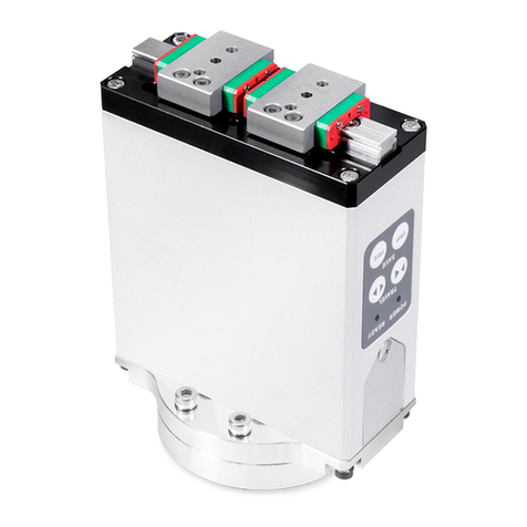
Hiwin E1 MECHATROLINK-III Installation and operating instructions

www.hiwinmikro.tw
E1 MECHATROLINK-III Drive Complete Setup
with KEYENCE KV STUDIO
Application Note
MD37UE01-2306_V1.0

ii
Revision History
The version of the manual is also indicated on the bottom of the front cover.
Release Date
Version
Applicable Product
Revision Contents
Jun. 30th, 2023
1.0
E1 MECHATROLINK-III Drive
First edition.
Release Date
MD37UE01-2306_V1.0
Version

iii
Related Documents
Through related documents, users can quickly understand the positioning of this manual and the
correlation between manuals and products. Go to HIWIN MIKROSYSTEM’s official website → Download
→ Manual Overview for details (https://www.hiwinmikro.tw/Downloads/ManualOverview_EN.htm).

iv
Preface
This manual provides detailed information on the operation of PLC software KV STUDIO when E1
MECHATROLINK-III drive is used with KEYENCE KV-7000 series PLC.

v
Specifications of Software/Hardware
Name
Version of Software/Firmware
E1 Series MECHATROLINK-III Drive
Software (Thunder): 1.9.16.0 or above
Firmware: 2.8.16
KEYENCE KV-7500
Software (KV- STUDIO): 11.61 or above
Firmware: 2.400 or above
KEYENCE KV-XH04ML
Firmware: 1.106 or above

vi
Table of Contents
1. Communication and module setup.............................................................................................................. 1-1
1.1 Introduction of hardware device ................................................................................................. 1-2
1.2 IP setting and connection........................................................................................................... 1-4
1.3 Axis configuration .................................................................................................................... 1-12
2. Parameters setup ....................................................................................................................................... 2-1
3. Trial run...................................................................................................................................................... 3-1
3.1 Positioning control ..................................................................................................................... 3-2
3.2 Starting speed, acceleration and deceleration rate/time, acceleration curve................................ 3-4
4. Origin return ............................................................................................................................................... 4-1
4.1 Immediate Z-phase origin return ................................................................................................ 4-2
4.2 Limit switch rising edge.............................................................................................................. 4-3
4.3 Origin sensor and Z-phase......................................................................................................... 4-4

HIWIN MIKROSYSTEM CORP. 1-1
1. Communication and module setup
1. Communication and module setup.............................................................................................................. 1-1
1.1 Introduction of hardware device ................................................................................................. 1-2
1.2 IP setting and connection........................................................................................................... 1-4
1.3 Axis configuration .................................................................................................................... 1-12

Communication and module setup E1 MECHATROLINK-III Drive Complete Setup with KEYENCE KV STUDIO
1-2 HIWIN MIKROSYSTEM CORP.
MD37UE01-2306
1.1 Introduction of hardware device
Figure 1.1.1
KEYENCE KV-7500 is a controller composed of a CPU unit and one or more positioning motion units.
For the first use, users need to combine CPU unit and positioning motion unit and prepare a 24 VDC 1.8
A power supply for CPU unit. CPU unit is mainly used to connect with the computer, and positioning
motion unit is mainly used to connect with the drive.
Figure 1.1.2
Drive
Motor
CPU Unit
Positioning
Motion Unit
B
CPU Unit
D
C
A
Positioning Motion Unit
G
F
E

E1 MECHATROLINK-III Drive Complete Setup with KEYENCE KV STUDIO Communication and module setup
HIWIN MIKROSYSTEM CORP. 1-3
MD37UE01-2306
◼Field A
Model of CPU unit.
◼Field B
LCD screen display.
◼Field C
Computer USB port.
◼Field D
CPU unit network port.
◼Field E
LED display lights.
Red light: Unit connection failure.
Green light: Successful unit connection.
◼Field F
Model of positioning motion unit.
◼Field G
Motion unit network port.
Users need to adopt Keyence's special network cable for motion unit and drive; ordinary network
cables may not be able to communicate successfully.

Communication and module setup E1 MECHATROLINK-III Drive Complete Setup with KEYENCE KV STUDIO
1-4 HIWIN MIKROSYSTEM CORP.
MD37UE01-2306
1.2 IP setting and connection
1. For first-time setup, connect USB cable and network cable to CPU unit and the computer, and open
KV STUDIO software interface.
Figure 1.2.1
2. Create a new project.
(In this step, press NO in "Confirm unit setting information" to prevent automatic generation of unit
configuration, which will be set in step 6.)
Figure 1.2.2

E1 MECHATROLINK-III Drive Complete Setup with KEYENCE KV STUDIO Communication and module setup
HIWIN MIKROSYSTEM CORP. 1-5
MD37UE01-2306
3. Set IP address to 192.168.0.100, which is in the same network domain as the controller.
Figure 1.2.3
4. Switch KV STUDIO mode to Editor, so that the subsequent operations could be carried out.
Figure 1.2.4

Communication and module setup E1 MECHATROLINK-III Drive Complete Setup with KEYENCE KV STUDIO
1-6 HIWIN MIKROSYSTEM CORP.
MD37UE01-2306
5. Select USB as communication path.
Figure 1.2.5
6. Click Unit configuration on the upper left side, and then right-click to select Unit Editor.
Figure 1.2.6

E1 MECHATROLINK-III Drive Complete Setup with KEYENCE KV STUDIO Communication and module setup
HIWIN MIKROSYSTEM CORP. 1-7
MD37UE01-2306
7. Click "Acquire the configuration information of the unit connected to the PLC" and press Yes to read
the existing positioning motion unit model of the user.
Figure 1.2.7
8. When the models of CPU unit and positioning motion unit appear, click OK on the lower right side.
Figure 1.2.8

Communication and module setup E1 MECHATROLINK-III Drive Complete Setup with KEYENCE KV STUDIO
1-8 HIWIN MIKROSYSTEM CORP.
MD37UE01-2306
9. Check if the model under Unit configuration is consistent with the model of actual controller.
Figure 1.2.9
10.Check if the communication path is USB, and press PLC Transfer > Execute. At this time, the display
light on the upper right side of the positioning motion unit will turn from red to green (refer to Field E in
Figure 1.1.2), representing successful setup of CPU unit and positioning motion unit.
Figure 1.2.10

E1 MECHATROLINK-III Drive Complete Setup with KEYENCE KV STUDIO Communication and module setup
HIWIN MIKROSYSTEM CORP. 1-9
MD37UE01-2306
11.After completing unit editor settings, select Serial as communication path and click Comm settings >
Ethernet > Search destination.
Figure 1.2.11
12.Click the network card that is connected to CPU unit and then click on Execute.
Figure 1.2.12

Communication and module setup E1 MECHATROLINK-III Drive Complete Setup with KEYENCE KV STUDIO
1-10 HIWIN MIKROSYSTEM CORP.
MD37UE01-2306
13.After pressing Execute for a few seconds, the results will be displayed below. Select the connected
unit type and click Select.
Figure 1.2.13
14.Click OK to complete the connection.
Figure 1.2.14

E1 MECHATROLINK-III Drive Complete Setup with KEYENCE KV STUDIO Communication and module setup
HIWIN MIKROSYSTEM CORP. 1-11
MD37UE01-2306
15.Switch KV STUDIO mode to Monitor, and check if the motion unit models are turned to green lights,
indicating the connection between PC and CPU unit is established.
Figure 1.2.15
16.Check if the communication type of the drive is MECHATROLINK-III and is set to “Drive ready” state
(For detailed setting operation, please refer to "E Series Servo Drive Thunder Software Operation
Manual"). Set Access to Controller so that the positioning motion unit of Keyence controller can be
connected to the drive.
Figure 1.2.16

Communication and module setup E1 MECHATROLINK-III Drive Complete Setup with KEYENCE KV STUDIO
1-12 HIWIN MIKROSYSTEM CORP.
MD37UE01-2306
1.3 Axis configuration
1. Switch KV STUDIO mode to Editor. Click the positioning motion unit which will be connected to the
drive and open Axis configuration setting.
Figure 1.3.1
2. At this time, the following screen will appear. Double-clicking Servo on the right, and the icon of a
servo motor will appear on the left. Please enter the relevant information of the drive on the lower
right side.
Figure 1.3.2

E1 MECHATROLINK-III Drive Complete Setup with KEYENCE KV STUDIO Communication and module setup
HIWIN MIKROSYSTEM CORP. 1-13
MD37UE01-2306
3. Open the cover of drive panel and observe SW1 and SW2. The arrow direction of knob indicates
the station address of the drive, SW1 refers to tens digit, and SW2 refers to units digit. However,
some station addresses are not supported by the drive, as shown in the table in Figure 1.3.4. If
SW1=0, the value of SW2 cannot be a number from 0 to 2; if SW1=F, the value of SW2 cannot be a
number from 0 to F. If the station address of the drive is the above number, please turn the knobs of
SW1 and SW2 to avoid the above range and restart the power. Finally, enter the station address of
the drive to Station address shown in Figure 1.3.4.
Figure 1.3.3
Figure 1.3.4
Note:
If the drive is set to gantry, the slave’s SW2 needs to be set to 8, otherwise it may cause gantry communication
errors.

Communication and module setup E1 MECHATROLINK-III Drive Complete Setup with KEYENCE KV STUDIO
1-14 HIWIN MIKROSYSTEM CORP.
MD37UE01-2306
4. After completing station address setting, do not set up coordinate transformation at this time, which
will be set after coordinate unit in chapter 2.
Figure 1.3.5
5. Click PLC Transfer to import the existing setting values into the controller.
Figure 1.3.6
Table of contents
Other Hiwin Network Hardware manuals
Popular Network Hardware manuals by other brands

Dell
Dell SonicWALL NSA 5600 Getting started guide

Ubiquiti
Ubiquiti airVision-C quick start guide

Infrant Technologies
Infrant Technologies ReadyNAS 600 Getting started

Omron
Omron SYSMAC CS1W-SCB41-V1 Operation manual

Sony
Sony PWS-110RX1A Operation manual

Patton electronics
Patton electronics NetLink 2960 RAS datasheet