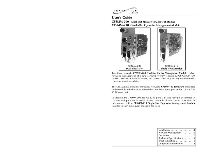
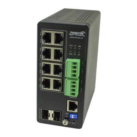
Transition Networks ION x6010 User manual

Transition Networks ION x6010 User Guide
33493 Rev. E https://www.transition.com/ Page 2 of 299
Trademarks
All trademarks and registered trademarks are the property of their respective owners.
Copyright Notice/Restrictions
Copyright © 2010-2018 Transition Networks. All rights reserved. No part of this work may be
reproduced or used in any form or by any means (graphic, electronic or mechanical) without written
permission from Transition Networks. Printed in the U.S.A.
ION System x6010 Managed T1/E1-to-Fiber Network Interface Device (NID) User Guide, 33493 Rev. E
Contact Information
Transition Networks
10900 Red Circle Drive
Minnetonka, MN 55343 USA
tel: +1.952.941.7600 | toll free: 1.800.526.9267 | fax: 952.941.2322
Revision History
Rev
Date
Description
A
05/23/11
Revised for firmware version 1.1.0.
B
09/08/11
Revised for firmware version 1.2.0.
C
12/23/16
Revised for firmware version 1.2.6 and updated default and LBO settings.
D
3/3/17
Add DoC and update contact information.
E
11/5/19
Update specifications and added optional accessories. Add Local
Management of Cards in a Remote Un-managed Chassis at FW v 1.2.6.
Update for FW v 2.0.1.

Transition Networks ION x6010 User Guide
33493 Rev. E https://www.transition.com/ Page 3 of 299
Cautions and Warnings
Definitions
Cautions indicate that there is the possibility of poor equipment performance or potential damage to
the equipment. Warnings indicate that there is the possibility of injury to person.
Cautions and Warnings appear here and may appear throughout this manual where appropriate. Failure
to read and understand the information identified by this symbol could result in poor equipment
performance, damage to the equipment, or injury to persons.
Cautions
Do not ship or store devices near strong electrostatic, electromagnetic, magnetic, or radioactive fields.
Caution: When handling chassis Network Interface Devices (NIDs) observe electrostatic discharge precautions. This
requires proper grounding (i.e., wear a wrist strap).
Caution: Copper based media ports, e.g., Twisted Pair (TP) Ethernet, USB, RS232, RS422, RS485, DS1, DS3, Video
Coax, etc., are intended to be connected to intra-building (inside plant) link segments that are not subject to
lightening transients or power faults. They are not to be connected to inter-building (outside plant) link segments
that are subject to lightening.
Caution: Do not install the NIDs in areas where strong electromagnetic fields (EMF) exist. Failure to observe this
caution could result in poor NID performance.
Caution: Read the installation instructions before connecting the chassis to a power source. Failure to observe this
caution could result in poor performance or damage to the equipment.
Caution: Only trained and qualified personnel should install or perform maintenance on the x6010. Failure to
observe this caution could result in poor performance or damage to the equipment.
Caution: Do not let optical fibers come into physical contact with any bare part of the body since they are fragile,
and difficult to detect and remove from the body.

Transition Networks ION x6010 User Guide
33493 Rev. E https://www.transition.com/ Page 4 of 299
Caution: Do not bend any part of an optical fiber/cable to a diameter that is smaller than the minimum permitted
according to the manufacturer’s specification (usually about 65 mm or 2.5 in)!
Warnings
Warning: Use of controls, adjustments or the performance of procedures other than those specified herein may
result in hazardous radiation exposure.
Warning: Visible and invisible laser radiation when open. Do not look into the beam or view the beam directly with
optical instruments. Failure to observe this warning could result in an eye injury or blindness.
Warning: DO NOT connect the power supply module to external power before installing it into the chassis. Failure
to observe this warning could result in an electrical shock or death.
Warning: Select mounting bracket locations on the chassis that will keep the chassis balanced when mounted in
the rack. Failure to observe this warning could allow the chassis to fall, resulting in equipment damage and/or
possible injury to persons.
Warning: Do not work on the chassis, connect, or disconnect cables during a storm with lightning. Failure to observe this
warning could result in an electrical shock or death.
See Appendix A on page 247 for Electrical Safety Warnings translated into multiple languages.

Transition Networks ION x6010 User Guide
33493 Rev. E https://www.transition.com/ Page 5 of 299
Table of Contents
Section 1: Introduction................................................................................................................... 10
Document Overview...............................................................................................................................10
Product Overview ...................................................................................................................................10
Features.................................................................................................................................................. 10
Typical Application..................................................................................................................................11
Applicable Standards and RFCs .............................................................................................................. 12
Feature Descriptions...............................................................................................................................12
AIS (Alarm Indication Signal) ..............................................................................................................12
Loopback Test.....................................................................................................................................13
LOS (Loss of Signal) Detection............................................................................................................ 14
In-band Fiber Loopback Code Detection............................................................................................14
HTTP ................................................................................................................................................... 15
Remote Management ........................................................................................................................17
Firmware Upgrade ............................................................................................................................. 19
Management Access Methods...........................................................................................................20
TFTP (Trivial File Transfer Protocol) ................................................................................................... 20
Optional Accessories (sold separately)...................................................................................................20
Models (Chassis and Standalone)...........................................................................................................21
Physical Specifications............................................................................................................................ 23
Connectors.............................................................................................................................................. 24
LED Descriptions ..................................................................................................................................... 25
Jumper Settings ...................................................................................................................................... 26
DIP Switches ...........................................................................................................................................26
Documentation Conventions..................................................................................................................29
Related Manuals and Online Help ..........................................................................................................30
For More Information ........................................................................................................................ 30
Section 2: Installation and System Setup......................................................................................... 31
General ................................................................................................................................................... 31
Installing the Chassis Model (C6010)......................................................................................................31
Installing the Standalone Model (S6010) ...............................................................................................32
Rack Mount Installation .....................................................................................................................32
Tabletop Installation .......................................................................................................................... 33
Wall Mount Installation...................................................................................................................... 34
Connecting to AC Power .................................................................................................................... 35
Installing SFPs ......................................................................................................................................... 36
Connecting the C6010 to the S6010.......................................................................................................36
Accessing the NIDs.................................................................................................................................. 40
Access via Local Serial Interface (USB) ...............................................................................................40
Access via an Ethernet Network.........................................................................................................41
Initialization (Default) Configuration......................................................................................................45
Section 3: Management Methods ................................................................................................... 46
General ................................................................................................................................................... 46
IONMM Managed x6010 ........................................................................................................................46
Managing Slide-In and Remote Modules Using CLI Commands ........................................................46

Transition Networks ION x6010 User Guide
33493 Rev. E https://www.transition.com/ Page 6 of 299
Managing Slide-In and Remote Modules via the Web Interface ....................................................... 50
Managing Standalone Modules Using CLI Commands....................................................................... 51
Managing Standalone Modules via the IONMM Web Interface........................................................ 52
Menu Descriptions ............................................................................................................................. 54
Reboot, Reset, and Power Off Function Notes ..................................................................................56
Section 4: Configuration ................................................................................................................. 59
General ................................................................................................................................................... 59
System Configuration .............................................................................................................................60
System Configuration –CLI Method .................................................................................................. 60
T1 System Configuration –Web Method...........................................................................................61
T1 Ports Configuration............................................................................................................................62
T1 Ports Configuration –CLI Method................................................................................................. 62
T1 Ports Configuration –Web Method ..............................................................................................63
Port Loopback Tests................................................................................................................................66
Port Loopback Test –CLI Method ...................................................................................................... 66
Port Loopback Test –Web Method ................................................................................................... 68
TDM Mode Configuration....................................................................................................................... 70
Configuring TDM Mode –CLI Method ............................................................................................... 70
Configuring TDM Mode –Web Method.............................................................................................71
Section 5: Operation ...................................................................................................................... 74
General ................................................................................................................................................... 74
Backup and Restore Operations (Provisioning)...................................................................................... 74
Note on Remote (L2D) Module Backup, Restore, and Upgrade ........................................................ 75
Backing Up Slide-In and Remote Module Configuration....................................................................75
Backing Up Standalone Modules ....................................................................................................... 78
Editing the Config File (Optional) ....................................................................................................... 80
Restoring Slide-In and Remote Modules’ Configuration.................................................................... 81
Restoring Standalone Modules .......................................................................................................... 84
Back Up and Restore File Content and Location ................................................................................87
IONMM Backup All / Restore All ........................................................................................................87
Displaying Information ........................................................................................................................... 88
Reset to Factory Defaults ....................................................................................................................... 88
Resetting Defaults –CLI Method........................................................................................................ 88
Resetting Defaults –Web Method..................................................................................................... 89
File Status after Reset to Factory Defaults.........................................................................................89
Resetting Uptime.................................................................................................................................... 90
Reset Uptime –CLI Method ...............................................................................................................90
Reset Uptime –Web Method ............................................................................................................91
Reboot ....................................................................................................................................................92
Rebooting –CLI Method.....................................................................................................................92
Rebooting –Web Method..................................................................................................................93
Reboot File Content and Location......................................................................................................94
Upgrade the IONMM and/or NID Firmware...........................................................................................95
Upgrading IONMM and/or NID Firmware –CLI Method ...................................................................95
Upgrading IONMM and/or NID Firmware –Web Method ................................................................97
Upgrading Slide-In and Remote Modules Firmware via TFTP ..............................................................103
Firmware Upgrade File Content and Location .................................................................................107
Transition Networks ION x6010 User Guide
33493 Rev. E https://www.transition.com/ Page 7 of 299
Additional Upgrade Procedures ....................................................................................................... 107
Replacing a Chassis Resident NID ......................................................................................................... 108
Section 6: Command Line Interface (CLI) Reference....................................................................... 109
General ................................................................................................................................................. 109
Command Line Editing..........................................................................................................................109
Display Similar Commands ...............................................................................................................109
Partial Keyword Lookup ...................................................................................................................109
Recall Commands .............................................................................................................................109
Keystroke Commands....................................................................................................................... 110
Command Descriptions ........................................................................................................................111
Section 7: Troubleshooting........................................................................................................... 127
General ................................................................................................................................................. 127
Basic ION System Troubleshooting....................................................................................................... 127
Error Indications and Recovery Procedures ......................................................................................... 128
LED Fault and Activity Displays.............................................................................................................129
Problem Conditions .............................................................................................................................. 130
CLI Messages.........................................................................................................................................141
Web Interface Messages ......................................................................................................................173
The Config Error Log (config.err) File.................................................................................................... 188
config.err Messages ......................................................................................................................... 189
config.err Message Responses......................................................................................................... 189
Webpage Messages.............................................................................................................................. 192
Windows Event Viewer Messages........................................................................................................202
ION System Tests.................................................................................................................................. 203
DMI (Diagnostic Maintenance Interface) Test .................................................................................203
Set Debug Level................................................................................................................................211
DIP Switches and Jumper Settings........................................................................................................212
PCB Identification............................................................................................................................. 212
C6010 PCB ........................................................................................................................................212
S6010 NID Switch Locations .............................................................................................................213
x6010-10xx PCB (C6010 with SFP and BNC) .....................................................................................217
In-band Loopback Code Detect Procedure ......................................................................................218
Third Party Troubleshooting Tools .......................................................................................................219
Third Party Tool Messages....................................................................................................................231
HyperTerminal Messages................................................................................................................. 231
Ping Command Messages ................................................................................................................ 234
Telnet Messages............................................................................................................................... 234
TFTP Server Messages......................................................................................................................236
PuTTY Messages............................................................................................................................... 237
Alarm Indication Signal –Alarm Condition........................................................................................... 238
LOS Detection ....................................................................................................................................... 240
T1 Error Events and Alarm Conditions.................................................................................................. 240
T1 Error Events .................................................................................................................................240
D4 and ESF Alarm Conditions...........................................................................................................240
Recovery Procedures........................................................................................................................ 241
Recording Model Information and System Information ...................................................................... 242
Technical Support ................................................................................................................................. 244

Transition Networks ION x6010 User Guide
33493 Rev. E https://www.transition.com/ Page 8 of 299
Contact Us ............................................................................................................................................244
Appendix A: Warranty and Compliance Information ..................................................................... 245
Warranty............................................................................................................................................... 245
Compliance Information....................................................................................................................... 246
Declaration of Conformity .................................................................................................................... 247
Electrical Safety ................................................................................................................................ 248
Elektrische Sicherheit .......................................................................................................................248
Elektrisk sikkerhed............................................................................................................................ 248
Elektrische veiligheid........................................................................................................................ 248
Sécurité électrique ...........................................................................................................................248
Sähköturvallisuus .............................................................................................................................248
Sicurezza elettrica ............................................................................................................................248
Elektrisk sikkerhet ............................................................................................................................248
Segurança eléctrica .......................................................................................................................... 248
Seguridad eléctrica...........................................................................................................................248
Elsäkerhet.........................................................................................................................................248
Appendix B: Factory Defaults ........................................................................................................ 249
Device-Level Factory Defaults ..............................................................................................................249
Port-Level Factory Defaults ..................................................................................................................249
Supported Line Build Out Matrix.......................................................................................................... 250
Appendix C: Configuration Quick Reference –CLI........................................................................... 251
For SNMP MIB Trap Information.......................................................................................................... 252
Appendix D: Cable Specifications................................................................................................... 253
Fiber Specifications...............................................................................................................................253
Fiber Cable............................................................................................................................................253
T1/E1 Cable........................................................................................................................................... 253
Twisted-Pair Copper Cable ................................................................................................................... 253
T1 TP/UTP.........................................................................................................................................253
E1 TP/UTP.........................................................................................................................................253
Appendix E: Local Management of Cards in a Remote Un-managed Chassis.................................... 254
Glossary........................................................................................................................................ 263
Index ............................................................................................................................................ 297
List of Figures
Figure 1: Typical x6010 User Application Scenario .....................................................................................11
Figure 2: Typical AIS Application................................................................................................................. 12
Figure 3: Loopback on copper and fiber port of Media Converter A..........................................................13
Figure 4: Typical Loopback function on a Fiber port...................................................................................14
Figure 5: Typical Loopback function on a Copper port...............................................................................14
Figure 6: Typical Remote Management Application................................................................................... 17
Figure 7: x6010 Remote Management Topology .......................................................................................18
Figure 8: x6010 Models............................................................................................................................... 21
Figure 9: C6010 Front Panels ......................................................................................................................24

Transition Networks ION x6010 User Guide
33493 Rev. E https://www.transition.com/ Page 9 of 299
Figure 10: S6010 Front Panels .................................................................................................................... 25
Figure 11: S6010 DIP Switches ....................................................................................................................26
Figure 12: C6010 DIP Switches....................................................................................................................27
Figure 13: Chassis Installation.................................................................................................................... 31
Figure 14: Tabletop Installation ................................................................................................................. 33
Figure 15: Wall Mount Installation ............................................................................................................34
Figure 16: AC Power Connection ...............................................................................................................35
Figure 17: SFP Installation.......................................................................................................................... 36
Figure 18: CLI Location Hierarchy .............................................................................................................. 47
Figure 19: x6010 PCB Layout..................................................................................................................... 212
Figure 20: x6010 Switch Locations............................................................................................................ 213
Figure 21: x6010-10xx Layout ...................................................................................................................217
Figure 22: Initiate a Loopback from a Test Set .........................................................................................218
List of Tables
Table 1: HTTP Parameters........................................................................................................................... 15
Table 2: x6010 Models................................................................................................................................ 22
Table 3: Physical Specifications................................................................................................................... 23
Table 4: x6010 Connector Descriptions ...................................................................................................... 24
Table 5: Documentation Conventions ........................................................................................................ 29
Table 6: System-Level Menu Description....................................................................................................54
Table 7: Port-Level Menu Description ........................................................................................................ 55
Table 8: Back Up and Restore File Content and Location ..........................................................................87
Table 9: File Status after a Reset to Factory Defaults .................................................................................89
Table 10: File Content and Location after a System Reboot....................................................................... 94
Table 11: File Content and Location after a Firmware Upgrade............................................................... 107
Table 12: Keystroke Editing Commands ...................................................................................................110
Table 13: DMI Parameters ........................................................................................................................205
Table 14: Device-Level Factory Defaults................................................................................................... 249
Table 15: Port-Level Factory Defaults.......................................................................................................249
Table 16: Line Build Out (LBO) Details ......................................................................................................250

Transition Networks ION x6010 User Guide
33493 Rev. E https://www.transition.com/ Page 10 of 299
Section 1: Introduction
Document Overview
This manual provides the user with an understanding of the Transition Networks (TN) x6010 Network
Interface Device (NID).
Product Overview
The ION T1/E1 model x6010 is a copper-to-fiber NID with remote management that provides a solution
to extend T1 or E1 circuits over fiber, and remotely manage them in-band from admin locations.
The x6010 NIDs are designed as either a standalone module (S6010) or a slide-in module (C6010) that is
installed in an ION system chassis. In either configuration, these devices are designed to convert the
copper ports on T1/E1 devices, such as a PBX or T1/E1 router, to multimode or single mode fiber with
advanced services and functions.
The x6010 supports Small Form Pluggable (SFP) transceivers to support a variety of fiber types, distances
and wavelengths to provide maximum flexibility across a variety of network topologies. The use of
Coarse Wave Division Multiplexing (CWDM) SFPs can be utilized to further increase the bandwidth
capacity of the fiber infrastructure. The T1/E1NID must be used in pairs. A typical installation includes a
chassis card (C6010) installed in a local ION chassis and a stand-alone device (S6010) installed at a
remote location.
Features
The x6010 provides the following services and functions.
•Converts copper ports on T1/E1 devices, such as a PBX or T1/E1 router, to multimode or single
mode fiber
•Alarm Indication Signal (AIS) LED
•Can be used with fractional T1/E1 circuits
•Firmware upgrade
•Remote management
•Local or Remote Loopbacks on copper or fiber port
•Switch-selectable RJ-48 connectors for T1 or E1
•Jitter attenuators optimize Bit Error Rate performance
•Network debug procedures make BER testing more convenient
•Built-in troubleshooting with selectable TAOS (Transmit All Ones): a switch on the fiber and
copper interfaces allows testing of all T1/E1 equipment on that network segment to ensure the
network links

Transition Networks ION x6010 User Guide
33493 Rev. E https://www.transition.com/ Page 11 of 299
You can manage the following x6010 services and functions via the x6010 application software:
•Report Model information, such as serial number, model number, firmware revision, etc.
•Report link status on copper and fiber ports
•Report LBO, Long Haul, Short Haul status
•Report AIS detected status on copper and fiber port
•Loopback Enable/Disable on copper or fiber port
•TAOS Enable/Disable on copper and fiber port
•Report circuit ID on device and ports
•DMI on Fiber port
Typical Application
The x6010 applications can include:
•Interconnect campus / MAN. A T1 link is a common means of campus / Metropolitan Area
Network (MAN) interconnects.
•Extend a T1 to other buildings in a campus or MAN.
•Link two PBXs or extend T1 from a demarc (demarcation point).
Figure 1: Typical x6010 User Application Scenario

Transition Networks ION x6010 User Guide
33493 Rev. E https://www.transition.com/ Page 12 of 299
Applicable Standards and RFCs
The x6010 complies with the following hardware standards:
•ANSI T1.102, T1.403, and T1.408
•ITU I.431, G.703, G.736, G.775, and G.823
•ETSI 300-166, 300-233, and TBR12/13
•AT&T Pub 62411
•Regulatory Compliance for Emission: FCC Class A; EN55022 Class A
•Regulatory Compliance for Immunity: EN55024
•Safety Compliance: Unit: UL listed, CE Mark
•In T1 mode, declaring/clearing AIS detection complies with ANSI T1.231. In E1 mode, declar-
ing/clearing AIS detection complies with ITU G.775 or ETSI 300233, as selected.
The x6010 complies with the following IETF RFCs:
•HTTP protocol: IETF RFC 2616
•SNMP protocol: IETF RFC 1157, RFC 1158, and RFC 2578
•TFTP protocol: IETF RFC 1350
Feature Descriptions
The x6010 features are described in the following sub-sections.
AIS (Alarm Indication Signal)
The x6010 provides AIS (Alarm Indication Signal) support.
When the x6010 detects a signal lost or framing lost on one port’s receiving direction, it will send out an
Alarm Indication Signal (AIS) through another port to alert the receiving end that a segment of the end-
to-end link has failed at a logical or physical level.
The x6010 will generate the AIS by transmitting all ones (TAOS).
You can enable or disable AIS transmit on each x6010 port via the Web interface, FocalPoint (FP), and
the Command Line Interface (CLI).
Media
Converter A
TX
RX
Copper Port
RJ-48/BNC
Fiber Port
End
Device A
Media
Converter B
RX
TX
Copper Port
RJ-48/BNC
Fiber Port
End
Device B
(1)
(1) Copper Port in End Device A detects a signal lost
(2) End Device A transmits AIS signal through Fiber Port to End Device B
(2)
Figure 2: Typical AIS Application

Transition Networks ION x6010 User Guide
33493 Rev. E https://www.transition.com/ Page 13 of 299
The AIS transmit function can be enabled or disabled on each port (Copper Port and Fiber Port) by set-
ting TAOS to Enable or Disable. If the AIS transmit function is enabled on one port and signal lost is de-
tected, the x6010 will transmit all ones to the receiving end device; if the AIS function is disabled, no ac-
tion will be performed.
If the x6010 receives an AIS signal (All Ones frame) from one port, the LED (SDC/SDF- Signal Detect on
Copper/Fiber) displays as yellow to indicate AIS is detected on that port (see “LED Descriptions” on page
29). The x6010 software transmits an AIS detect trap at the same time (see the “SNMP MIBs”section on
page 21 for trap descriptions).
If Media Converter A in Figure 2 above detects a signal lost on a copper port and the AIS function is ena-
bled (TAOS is enabled) on that port, Media Converter A will Transmit All Ones to Media Converter B
through the fiber link. Media Converter B’s SDF LED will display as yellow to indicate an AIS signal is de-
tected on the fiber port. The AIS signal will then be transmitted to End Device B.
In T1 mode, the criteria for declaring/clearing AIS detection are in compliance with the ANSI T1.231.
In E1 mode, the criteria for declaring/clearing AIS detection comply with the ITU G.775 or the ETSI
300233, as selected.
Loopback Test
The x6010 provides Loopback (LB) test support with three different loopback configurations: copper
loopback, fiber loopback, and inband loopback.
The Loopback feature puts the x6010 in a mode that lets it loop back the signal from the RX port to the
TX port on either media for testing and troubleshooting purposes. You can enable or disable the
Loopback function on an x6010 copper port or fiber port via the Web interface, FocalPoint (FP), and the
Command Line Interface (CLI).
Test signals from a test device (e.g., Fireberd, etc.) can then be inserted into the link and looped back
and received by a device to test a particular segment of the link (i.e., copper or fiber).
Media
Converter A
TX
RX
Copper Port
RJ-48/BNC
Fiber Port
End
Device A
Media
Converter B
RX
TX
Copper Port
RJ-48/BNC
Fiber Port
End
Device B
(1)
(1) Loopback on copper port;
(2) Loopback on fiber port.
(2)
Figure 3: Loopback on copper and fiber port of Media Converter A
If the Loopback function is enabled on the copper port of Media Converter A, End Device A is the tester;
the test signal is inserted into the copper RX of Media Converter A and then looped back and received
by the copper TX of Media Converter A.

Transition Networks ION x6010 User Guide
33493 Rev. E https://www.transition.com/ Page 14 of 299
If the Loopback function is enabled on the Fiber port of Media Converter A, End Device B is the tester;
the test signal will be inserted into the Fiber RX of Media Converter A through Media Converter B and be
looped back at Fiber port of Media Converter A and received by End Device B via Media Converter B.
The x6010 Loopback function cannot be enabled on both copper and fiber ports at the same time; an
error message displays if attempted.
A typical x6010 Fiber port Loopback applications is shown below.
Figure 4: Typical Loopback function on a Fiber port
A typical x6010 Copper port Loopback applications is shown below.
Figure 5: Typical Loopback function on a Copper port
LOS (Loss of Signal) Detection
The x6010 Loss of Signal (LOS) detector monitors the amplitude of the incoming signal level and pulse
density of the received TIP/RING signals. A LOS condition is detected when the incoming signal has “no
transitions”. The LOS condition is cleared when the incoming signal has “transitions”. In addition, the
x6010 application software may get the LOS status via interface with the FPGA. LOS detection is pro-
vided on the x6010 coax, fiber and copper interfaces as link down and link up traps and show com-
mands.
In-band Fiber Loopback Code Detection
This function enables detection and loopback of the fiber interface based on NIU Facility 2 (FAC2) loop-
back codes. Certain test devices (e.g., T-BERD 2310) can send in-band loopback codes to the local copper
(TP) interface, which are then transmitted to the remote device via the fiber. The remote device can de-
tect and react to this and activate and de-activate the loopback codes. For detection, these codes must
be sent for at least 5 seconds.

Transition Networks ION x6010 User Guide
33493 Rev. E https://www.transition.com/ Page 15 of 299
The Inband Fiber Loopback Code Detector can track loopback activate/deactivate codes in a framed or
unframed T1 data stream. The received data stream is compared with the target activate/deactivate
code whose length and the content are pre-defined. When the received data stream matches the target
activate/deactivate code and repeats for 4 seconds, this register field indicates the detection of the in-
band loopback code.
HTTP
You can manage the x6010 via the IONMM’s HTTP service to check all of the configuration parameters
and modify some of them via the Web interface.
The table below shows the Global, Fiber port, and Copper port parameters, their Properties, and the
valid range of entries supported. The Properties column shows “Read only” (parameters that can only be
displayed) or “Read & Write” (parameters that are user-configurable), or “Button”.
Table 1: HTTP Parameters
Parameter
Property
Range
Global Parameters
Serial number
Read only
Model number
Read only
Software Revision
Read only
Hardware Revision
Read only
Bootloader Revision
Read only
System Name
Read & Write
Alpha, numeric, and special characters allowed;
spaces between characters not allowed.
System Uptime
Read only
Configuration Mode
Read only
Hardware | Software
Number of Ports
Read only
System Reboot
Button
Reset to Factory Defaults
Button
TDM Mode
Read only
T1 | E1
Device Description
Read & Write
Device description display string of up to 64 al-
pha, numeric or special characters.
Fiber Port Parameters
- Link
Read only
Down | Up
- Transmit All ones
Read & Write
Enable | Disable
- AIS Transmit
Read & Write
Enable | Disable
- Alarm Indication Signal
Read only
Normal | Alarm
- Loopback
Read & Write
No Loopback | PHY Layer
- Connector
Read only
Description string of connector
- Circuit ID
Read & Write
Circuit ID display string
- DMI
DMI ID
Read only
Connector Type
Read only

Transition Networks ION x6010 User Guide
33493 Rev. E https://www.transition.com/ Page 16 of 299
Nominal Bit Rate
Read only
Wavelength
Read only
Receive Power
Read only
Receive Power Alarm
Read only
Normal | Low Warning | High Warning | Low
Alarm | High Alarm
Rx Power Intrusion Threshold
Read & Write
0-65,535
Temperature
Read only
Temperature Alarm
Read only
Normal | Low warning | high warning | low
Alarm | high Alarm
Transmit Bias
Read only
Transmit Bias Alarm
Read only
Normal | Low warning | high warning | low
Alarm | high Alarm
Transmit Power
Read only
Transmit Power Alarm
Read only
Normal | Low warning | high warning | low
Alarm | high Alarm
Length (Single Mode)
Read only
Length (50um, Multi Mode)
Read only
Length (62.5 um, Multi Mode)
Read only
Length (copper)
Read only
Copper Port
- Link
Read only
Down | Up
- Transmit All ones
Read & Write
Enable | Disable
- AIS Transmit
Read & Write
Enable | Disable
- Alarm Indication Signal
Read only
Normal | Alarm
- Loopback
Read & Write
No Loopback | PHY Layer
- Long Haul
Read only
Yes | No
- Line build out
Read only
Description string of LBO
- Connector
Read only
Description string of connector
- Circuit ID
Read & Write
Circuit ID display string

Transition Networks ION x6010 User Guide
33493 Rev. E https://www.transition.com/ Page 17 of 299
Remote Management
Remote Management over fiber allows access to the remote device to obtain status, actively configure
remote device features, and perform remote device firmware upgrades.
A typical remote management scenario is shown below.
Figure 6: Typical Remote Management Application
In the figure above, devices from Customer A to Customer E can all be remotely managed via the TN
Chassis.
A remote S6010 device is connected with local C6010 device through the fiber link, with a specific
channel on the fiber link reserved and used for the management traffic. This management channel is in-
dependent of the TDM payload channels; the management channel and TDM payload channels will not
impact each other.
The x6010 Remote Management (RM) protocol lets applications exchange management traffic between
local C6010 and remote S6010 devices. The RM protocol provides the interaction protocol for Packet
Handling, BC Packet TX/RX and Remote Packet TX/RX. The RM protocol provides transparent packet for-
warding on the C6x10 and packet TX/RX redirection on the S6x10, eliminating the differences
between the C6x10 and S6x10 for the IONMM and its upper layer applications.
Note that the current ION platform supports up to one level of x6010 device remote management.
Version 1.2.6 of the x6010 Series supports the management of a C6010 when installed in an unmanaged
ION chassis. Management is supported by another C6010 installed in a managed chassis when the two
are linked together via a fiber cable. Version 1.2.6 also supports remote firmware upgrades of a C6010 in
an unmanaged chassis. See the Release Notes for known Feature limitations.

Transition Networks ION x6010 User Guide
33493 Rev. E https://www.transition.com/ Page 18 of 299
All management traffic between the IONMM and the remote S6010 are relayed and forwarded through
the local C6010. Traffic between the IONMM and C6010 is exchanged on the ION chassis’ backplane
Ethernet bus (BPC), while traffic between the local C6010 and remote S6010 is exchanged on the specific
management channel (see figure below) .
Fiber port
Fiber port
Copper port
Copper port
IONMM
C6010
S6010
Backplane Ethernet Bus
Chassis
management channel
Figure 7: x6010 Remote Management Topology
Remote devices are detected by the IONMM through the internal LLDP protocol. Each time a remote de-
vice is powered up, it periodically sends out an LLDP packet to notify the IONMM that it is up.
When the IONMM receives such LLDP packets, it updates the entire ION topology based on the infor-
mation carried in the LLDP packet.

Transition Networks ION x6010 User Guide
33493 Rev. E https://www.transition.com/ Page 19 of 299
Firmware Upgrade
The x6010 can be upgraded via an IONMM installed in an ION chassis. You can select the target NID via
the Web interface / Focal Point / CLI and start the firmware upgrade operation. After the x6010 finishes
upgrading, it will reboot itself to load the new firmware. The upgrades do not require reconfiguration of
the SNMP management or converter feature settings.
The x6010 has two parts that need to be upgraded; one is the device firmware (AVR) and the other is
the FPGA (Field Programmable Gate Array) firmware. For simplicity, these two parts are combined into
one firmware file and upgraded in one step, transparently.
You can upgrade the x6010 to a specific revision via the IONMM, which means the x6010 can be up-
graded to a newer revision firmware or can be downgraded to an older revision firmware. (Attempting
to upgrade to the existing revision firmware version is not actually performed, and a message displays
indicating this.)
Certain conditions will cause the firmware upgrade to fail:
•The communication path between x6010 and IONMM is corrupted, causing an upgrade protocol
timeout,
•No valid firmware file stored in the IONMM (e.g., no specified x6010 firmware revision, or a cor-
rupted firmware file).
•The firmware revision is the same.
•Programming the internal Flash fails.
If the x6010 bootloader cannot detect valid firmware installed after device is powered up or rebooted, it
enters upgrade mode automatically to request valid firmware from the IONMM. When the x6010 fin-
ishes upgrading successfully, it reboots itself and the bootloader checks the firmware again. If it passes,
the x6010 loads the new firmware and enters normal operating mode. Otherwise, the x6010 returns to
Upgrade mode. Note: Only the x6010 in the process of being upgraded will have its FPGA forced into
factory mode. The FPGA mode of the connected x6010 remains in application mode. A C6010 can only
upgrade a remote S6010 with the same version number.
The three methods of firmware upgrades are:
•Web interface
•Focal Point
•CLI command
A remotely-managed x6010 can be upgraded remotely as mentioned above. Note that the current ION
platform supports up to one level of x6010 device remote management.

Transition Networks ION x6010 User Guide
33493 Rev. E https://www.transition.com/ Page 20 of 299
Management Access Methods
Management of the x6010 is accomplished through one of the following methods.
• Universal Serial Bus (USB) –uses a command line interface (CLI) to access and control the x6010
through a locally connected workstation.
• Telnet session –uses the CLI to access and control the x6010 through the network.
• Simple Network Management Protocol (SNMP) –both public and private Management
Information Bases (MIBs) allowing for a user to easily integrate and manage the ION platform
with an SNMP based network management system (NMS).
TFTP (Trivial File Transfer Protocol)
The TFTP client provides uploading and downloading of files out of the device’s file system. Typical
applications for this protocol on this device include backup of configuration, restore known
configuration from a file, firmware image upgrade/downgrade, log files backup, certificate download for
SSL applications etc.
Optional Accessories (sold separately)
SFP Modules: SFP port uses standard 100Base-x/oc-3 SFP. See the TN SFP webpage.
Power Supply: SPS-2460-SA Wide Input (24 - 60VDC) Stand-Alone Power Supply included.
Mounting Options:
WMBL Wall Mount Bracket 4" [102 mm]
WMBD DIN Rail Bracket 5" [127 mm]
E-MCR-05 12-Slot Media Converter Rack
RMS19-SA4-02 4-Slot Media Converter Shelf
Country-specific Power Supply: To order the corresponding country specific power supply, add the
extension from the list below to the end of the SKU; -NA = Country Code, NA = North America, LA = Latin
America, EU = Europe, UK = United Kingdom, SA = South Africa, JP = Japan, OZ = Australia, BR = Brazil.
Table of contents
Other Transition Networks Network Hardware manuals

Transition Networks
Transition Networks SISPM1040-582-LRT User manual

Transition Networks
Transition Networks SwitchMaster MSB-E6/X2 User manual

Transition Networks
Transition Networks INDUSTRIAL DEVICE SERVER SDSFE31XX-100 User manual

Transition Networks
Transition Networks CPSMM-200 User manual

Transition Networks
Transition Networks SBFTF1010-130 User manual