HK Instruments DPI Series User manual

Copyright HK Instruments 2014 www.hkinstruments. Installation version 2.0 2014
INSTALLATION
INSTRUCTIONS
DIFFERENTIAL PRESSURE SWITCHES
DPI Series
WARNING
• READ THESE INSTRUCTIONS CAREFULLY BEFORE
ATTEMPTING TO INSTALL, OPERATE OR SERVICE THIS
DEVICE.
• Failure to observe safety information and comply with
instructions can result in PERSONAL INJURY, DEATH AND/OR
PROPERTY DAMAGE.
• To avoid electrical shock or damage to equipment, disconnect
power before installing or servicing and use only wiring with
insulation rated for full device operating voltage.
• To avoid potential fire and/or explosion do not use in potentially
flammable or explosive atmospheres.
• Retain these instructions for future reference.
• This product, when installed, will be part of an engineered
system whose specifications and performance characteristics
are not designed or controlled by HK Instruments. Review
applications and national and local codes to assure that the
installation will be functional and safe. Use only experienced
and knowledgeable technicians to install this device.
SPECIFICATIONS
INTRODUCTION
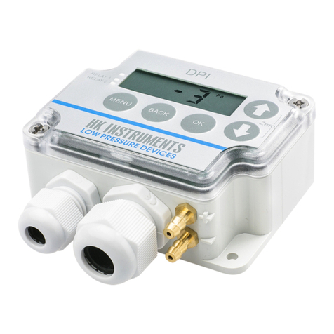
Thank you for choosing an HK Instruments DPI series electronic
differential pressure switch. The DPI series is intended for use
in commercial environments. It combines the advantages of an
electronic differential pressure switch (on-off relay) and a multi-
functional differential pressure transmitter to meet your job re-
quirements.
The DPI series is comprised of the DPI±500 with bi-directional
measurement ranges from ±100 to ±500 Pa and the DPI2500 with
measurement ranges from 100 to 2500 Pa.
All DPI series devices include one relay, display, manual pushbut-
ton zero point calibration and span point calibration. Optional fea-
tures include a second relay and autozero calibration.
APPLICATIONS
DPI series devices are commonly used in HVAC/R systems for:
• fan, blower and filter monitoring
• staircase pressure monitoring and alarm
• pressure monitoring in cleanrooms
• boiler pressure monitoring and alarm
SPECIFICATIONS
Performance
Accuracy:
±0.7 % (±1.5 % initial)
%/FS from highest pressure range including:
general accuracy, temperature drift, linearity, hysteresis,
and repetition error.
Long term stability:
Typical 1 year
With autozero: ±1 Pa
Without autozero: ±8 Pa
Overpressure:
Proof pressure: 25 kPa
Burst pressure: 30 kPa
Zero point calibration:
Automatic with autozero (-AZ) circuit or
Manual via menu
Response time:
0.5–10 s, selectable via menu
Technical Specifications
Media compatibility:
Dry air or non-aggressive gases
Measuring units:
Pa, kPa, mmWC, inWC, mbar selectable via menu
Measuring element:
Piezoresistive
Environment:
Operating Temperature:
Without autozero : -10...50 °C
With autozero: -5...50 °C
Storage temperature: -20...70 °C
Humidity: 0 to 95 % rH, non condensing
Physical
Dimensions:
Case: 89 x 86.5 x 37.1 mm
Weight:
150 g
Mounting:
Case: 2 each 4.3 mm holes
Lid: 2 each 4.3 mm holes
Materials:
Case: ABS
Lid: PC
Duct connectors: ABS
Tubing: PVC
Protection standard:
IP54
Touch sensitive buttons on the lid:
Menu, Back, OK, down arrow, up arrow
Display:
3 1/2 digit LCD backlit display
Size: 46.0 W x 14.5 H mm
Electrical connections:
n/out:
Terminal block (24 V, GND, 0–10 V)
Wire: 12–24 AWG (0.2–1.5 mm2)
Relay 1:
Terminal block (NC, COM, NO)
Wire: 12–24 AWG (0.2–1.5 mm2)
Relay 2:
Terminal block (NC, COM, NO)
Wire: 12–24 AWG (0.2–1.5 mm2)
Cable entries:
Strain relief: M16 & M20
Knockout : 16 mm
Knockout : 20 mm
Pressure fittings:
5.2 mm barbed brass
+ High pressure
− Low pressure
Electrical
Circuit: 3-wire (24 V, GND, 0–10 V)
Input:
Without autozero: 21–35 VDC/ 24 VAC, ±10 %
With autozero: 24 VAC or VDC, ±10 %
Output:
Analog: 0–10 V
Relay 1: 250 VAC / 30 VDC / 6 A
Relay 2: 250 VAC / 30 VDC / 6 A
Resistance minimum: 1 kΩ
Current consumption:
35 mA + relays (7 mA each) + AZ circuit (20 mA)
+ 0–10 V output (10 mA)
Conformance
Meets requirements for CE marking:
EMC Directive 2004/108/EC
RoHS Directive 2002/95/EC
LVD Directive: 2006/95/EC

Copyright HK Instruments 2014 www.hkinstruments. Installation version 2.0 2014
SCHEMATICS
DIMENSIONAL DRAWINGS
INSTALLATION
Figure 1a - Surface mounting
STEP 1: MOUNTING THE DEVICE
1) Mount the device in the desired location (see step 1).
2) Open the lid and route the cable(s) through the strain relief(s) and
connect the wires to the terminal block(s) (see step 2).
3) The device is now ready for configuration.
WARNING! Apply power only after the device is properly wired.
1) Select the mounting location (duct, wall, panel).
2) Use the device as a template and mark the screw holes.
3) Mount with appropriate screws.
Figure 1b - Mounting orientation
Figure 1c - Application connections
24 V GND 0–10 V
Terminal block Terminal block for relays
NC COM NO NC COM NO
37.1
89.0
86.5
74.5
64.5
52.5
4.2
YES NO NO
Static pressure Filter/Damper
monitoring
Fan/Blower
monitoring
Not
connected

Copyright HK Instruments 2014 www.hkinstruments. Installation version 2.0 2014
STEP 2: WIRING DIAGRAMS CONFIGURATION CONTINUED
For CE compliance, a properly grounded shielding cable is required.
1) Unscrew the strain relief and route the cable(s). Use separate
strain relief for the 0–10 V output cable and the relay cable(s).
2) Connect the wires as shown in figure 2a and 2b.
3) Tighten the strain relief.
Figure 2a - Wiring diagram 0–10 V output
Figure 2b - Wiring diagram relay(s)
STEP 3: CONFIGURATION
1) Select the desired measurement unit.
2) Select the desired measurement range.
3) Select the desired response time.
4) Configure the relay(s).
5) Zero the device.
6) Calibrate the span point.
7) Connect the pressure tubes. Connect positive pressure to port
labeled "+" and negative pressure to port "-".
The device is now ready to be used.
24 V
GND
Pout
Power supply
24 VDC / 24 VAC
+
Output 0...10 V
V
+
/
Pa, kPa, mmH2O, inchWC, mbar
Pressure range selection
Response time
Relay menu(s)
Zero point calibration
Response time
High point calibration menu
High point calibration
Reset high point calibration
Relay activation menu
Relay setpoint
Relay hysteresis 0–5 % of range
Relay activation on increasing pressure
Relay activation on decreasing pressure
NC
COM
NO
Relay 1
NC
COM
NO
Relay 2
With the MENU button you can enter the menu by pressing the button for
3 seconds. You can exit the menu without making any
changes.
With the BACK button you can return without making changes.
With the OK button you can open new options or conrm changes and return
to previous display.
With the buttons you can scroll the menus.

Copyright HK Instruments 2014 www.hkinstruments. Installation version 2.0 2014
STEP 4: ZEROING THE DEVICE
To zero the device two options are available:
1) Manual Pushbutton zero point calibration
2) Autozero calibration
Does my transmitter have an autozero calibration? See the product
label. If it shows -AZ in the model number, then you have the au-
tozero calibration.
1) Manual Pushbutton zero point calibration
NOTE: Supply voltage must be connected at least one hour prior to
zero point adjustment.
a) Disconnect both pressure tubes from the pressure ports labeled
+ and –.
b) Push both arrow buttons on top of the lid shortly or go to
configuration menu and select “Zero”.
c) The zeroing of the device will proceed automatically when the
green led on top of the lid turns off and “Zero” text followed by
a counter from 3 to 0 seconds appears on the display. The
zeroing is complete when the green led turns on again.
d) Reinstall the pressure tubes ensuring that the High pressure
tube is connected to the port labeled +, and the Low pressure
tube is connected to the port labeled −.
NOTE: The zero point should be calibrated via manual autozero, one
hour after installation and at least every 12 months during normal
operations.
2) Autozero calibration
If the device includes the optional autozero circuit, no action is re-
quired.
Autozero calibration (-AZ) is an autozero function in the form of an au-
tomatic zeroing circuit built into the PCB board. The autozero calibra-
tion electronically adjusts the transmitter zero at predetermined time
intervals (every 10 minutes). The function eliminates all output signal
drift due to thermal, electronic or mechanical effects, as well as the
need for technicians to remove high and low pressure tubes when
performing initial or periodic transmitter zero point calibration. The au-
tozero adjustment takes 4 seconds after which the device returns to
its normal measuring mode. During the 4 second adjustment period,
the output and display values will freeze to the latest measured value.
Transmitters equipped with the autozero calibration are virtually
maintenance free.
WARRANTY POLICY
The seller is obligated to provide a warranty of 24 months for the de-
livered goods regarding material and manufacturing. The warranty
period is considered to start on the delivery date of the product. If
a defect in raw materials or a production flaw is found, the seller is
obligated, when the product is sent to the seller without delay or be-
fore expiration of the warranty, to amend the mistake at his/her dis-
cretion either by repairing the defective product or by delivering free
of charge to the buyer a new flawless product and sending it to the
buyer. Delivery costs for the repair under warranty will be paid by the
buyer and the return costs by the seller. The warranty does not com-
prise damages caused by accident, lightning, flood or other natural
phenomenon, normal wear and tear, improper or careless handling,
abnormal use, overloading, improper storage, incorrect care or re-
construction, or changes and installation work not done by the seller
or his/her authorized representative. The selection of materials for de-
vices prone to corrosion is the buyer’s responsibility, unless otherwise
is legally agreed upon. Should the manufacturer alter the structure of
the device, the seller is not obligated to make comparable changes to
devices already purchased. Appealing for warranty requires that the
buyer has correctly fulfilled his/her duties arisen from the delivery and
stated in the contract. The seller will give a new warranty for goods
that have been replaced or repaired within the warranty, however only
to the expiration of the original product’s warranty time. The warranty
includes the repair of a defective part or device, or if needed, a new
part or device, but not installation or exchange costs. Under no cir-
cumstance is the seller liable for damages compensation for indirect
damage.
Other HK Instruments Relay manuals
