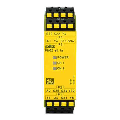
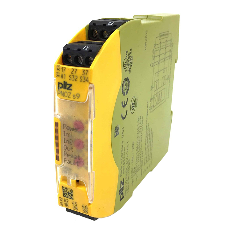
Pilz PNOZ e4.1p User manual

PNOZ e4.1p
Operating Manual-21362-EN-05
}Safety relays

Preface
This document is a translation of the original document.
All rights to this documentation are reserved by Pilz GmbH & Co. KG. Copies may be made
for internal purposes. Suggestions and comments for improving this documentation will be
gratefully received.
Source code from third-party manufacturers or open source software has been used for
some components. The relevant licence information is available on the Internet on the Pilz
homepage.
Pilz®, PIT®, PMI®, PNOZ®, Primo®, PSEN®, PSS®, PVIS®, SafetyBUS p®,
SafetyEYE®, SafetyNET p®, the spirit of safety® are registered and protected trademarks
of Pilz GmbH & Co. KG in some countries.
SD means Secure Digital

Contents
Operating Manual PNOZ e4.1p
21362-EN-05 3
Introduction 5
Validity of documentation 5
Using the documentation 5
Definition of symbols 5
Safety 6
Intended use 6
Safety regulations 7
Safety assessment 7
Use of qualified personnel 7
Warranty and liability 7
Disposal 7
For your safety 8
Unit features 8
Safety features 8
Block diagram/terminal configuration 9
Function description 9
Operating modes 10
Installation 10
Wiring 11
Preparing for operation 12
Supply voltage 12
Input circuit 12
Start circuit 13
Feedback loop 14
Logic connection between several units 14
Logic inputs S35 and S36 15
Examples 15
Operation 20
Status indicators 20
Faults - malfunctions 21
Dimensions in mm 26
Technical details 26
Safety characteristic data 29

PNOZ e4.1p
Operating Manual PNOZ e4.1p
21362-EN-05 5
Introduction
Validity of documentation
This documentation is valid for the product PNOZ e4.1p. It is valid until new documentation
is published.
This operating manual explains the function and operation, describes the installation and
provides guidelines on how to connect the product.
Using the documentation
This document is intended for instruction. Only install and commission the product if you
have read and understood this document. The document should be retained for future ref-
erence.
Definition of symbols
Information that is particularly important is identified as follows:
DANGER!
This warning must be heeded! It warns of a hazardous situation that poses
an immediate threat of serious injury and death and indicates preventive
measures that can be taken.
WARNING!
This warning must be heeded! It warns of a hazardous situation that could
lead to serious injury and death and indicates preventive measures that can
be taken.
CAUTION!
This refers to a hazard that can lead to a less serious or minor injury plus
material damage, and also provides information on preventive measures
that can be taken.
NOTICE
This describes a situation in which the product or devices could be dam-
aged and also provides information on preventive measures that can be
taken. It also highlights areas within the text that are of particular import-
ance.

PNOZ e4.1p
Operating Manual PNOZ e4.1p
21362-EN-05 6
INFORMATION
This gives advice on applications and provides information on special fea-
tures.
Safety
Intended use
The safety relay PNOZ e4.1p provides a safety-related interruption of a safety circuit.
The unit meets the requirements of EN ISO 13849-1 up to and including PL d (Cat. 3). The
safety mat only partially meets this requirement (see Clause 4.15 of EN ISO 13856-1).
They may only be used as a safety system in conjunction with safety mats that are spe-
cified in the unit features. The safety relay is used for signal processing and as a shutdown
device in accordance with ENISO 13856-1. When using safety mats, please refer to the
manufacturer's documentation.
When using safety mats, please note the following:
}The safety mats trigger only when they are stood on by persons weighing more than
35kg.
}The following are not permitted: Walking aids such as canes and wheeled vehicles
The following is deemed improper use in particular:
}Any component, technical or electrical modification to the product
}Use of the product outside the areas described in this manual
}Use of the product outside the technical details (see Technical details [ 26]).
NOTICE
EMC-compliant electrical installation
The product is designed for use in an industrial environment. The product
may cause interference if installed in other environments. If installed in other
environments, measures should be taken to comply with the applicable
standards and directives for the respective installation site with regard to in-
terference.

PNOZ e4.1p
Operating Manual PNOZ e4.1p
21362-EN-05 7
Safety regulations
Safety assessment
Before using a unit it is necessary to perform a safety assessment in accordance with the
Machinery Directive.
Functional safety is guaranteed for the product as a single component. However, this does
not guarantee the functional safety of the overall plant/machine. In order to achieve the re-
quired safety level for the overall plant/machine, define the safety requirements for the
plant/machine and then define how these must be implemented from a technical and organ-
isational standpoint.
Use of qualified personnel
The products may only be assembled, installed, programmed, commissioned, operated,
maintained and decommissioned by competent persons.
A competent person is a qualified and knowledgeable person who, because of their train-
ing, experience and current professional activity, has the specialist knowledge required. To
be able to inspect, assess and operate devices, systems and machines, the person has to
be informed of the state of the art and the applicable national, European and international
laws, directives and standards.
It is the company’s responsibility only to employ personnel who
}Are familiar with the basic regulations concerning health and safety / accident preven-
tion,
}Have read and understood the information provided in this description under "Safety"
}Have a good knowledge of the generic and specialist standards applicable to the spe-
cific application.
Warranty and liability
All claims to warranty and liability will be rendered invalid if
}The product was used contrary to the purpose for which it is intended
}Damage can be attributed to not having followed the guidelines in the manual
}Operating personnel are not suitably qualified
}Any type of modification has been made (e.g. exchanging components on the PCB
boards, soldering work etc.).
Disposal
}In safety-related applications, please comply with the mission time TM in the safety-re-
lated characteristic data.
}When decommissioning, please comply with local regulations regarding the disposal of
electronic devices (e.g. Electrical and Electronic Equipment Act).
PNOZ e4.1p
Operating Manual PNOZ e4.1p
21362-EN-05 8
For your safety
The unit meets all the necessary conditions for safe operation. However, please note the
following:
You must follow the instructions for installing the safety mats as stated in EN ISO 13856-1,
Annex B.5.
If you are using a safety mat system with reset function, the reset must occur outside of the
danger zone, with insight into the danger zone.
The function of the safety system must be checked at regular intervals.
Unit features
}Outputs using semiconductor technology:
– 2 safety outputs
– 1 auxiliary output
– 2 test pulse outputs
}Connection options:
– Safety mats from Mayser, type SM/BK
– Safety mats from Bircher, type ESM5x
}It is possible to control a PSS
}LED display for:
– Supply voltage
– Switch state of safety outputs
}2 logic inputs (AND/OR) for logic connections between several units
}Feedback loop for monitoring external contactors
}Detection of shorts across contacts via test pulse outputs
Safety features
The relay meets the following safety requirements:
}The circuit is redundant with built-in self-monitoring.
}The safety device remains effective in the case of a component failure.
}The safety outputs are tested periodically using an off-test.

PNOZ e4.1p
Operating Manual PNOZ e4.1p
21362-EN-05 9
Block diagram/terminal configuration
Input Feed-
back
Diag-
nostic
Test
Pulse
Output
&
Power
Input Start
A1 A2 S12 S22 Y4 S34 S35 S36 Y6
Y5 S11 S21 24
Y32 14
Function description
When supply voltage is applied and the set operating mode is detected (initialisation
phase), the "POWER" LED is lit. The unit is ready for operation when the feedback loop is
closed.
}Safety mat not activated:
– There are high signals at safety outputs 14 and 24 and auxiliary output Y32.
– The LEDs "CH.1" and "CH.2" are lit.
}Safety mat activated:
– There are low signals at safety outputs 14 and 24 and auxiliary output Y32.
– The LEDs "CH.1" and "CH.2" go out.
Feedback loop
Before a safety output is switched on, a test is run to establish whether the contacts ahead
of feedback loop input Y6 are closed. If a contact is open, an error is detected and LEDs
CH.1 and CH.2 will flash alternately. It will not be possible to switch the unit back on until
the feedback loop is closed and the safety function has been reset.
The feedback loop contacts are also checked when the signal at the output changes from
high to low. After this signal change, the contacts at the feedback loop input must close
within 150 ms. If a contact is still open after 150 ms has elapsed, an error is detected and is
displayed as a flashing code (1,8) (see Faults - malfunctions [ 21]). It will not be pos-
sible to switch the unit back on until the error has been rectified and the supply voltage has
been switched off and then on again.

PNOZ e4.1p
Operating Manual PNOZ e4.1p
21362-EN-05 10
AND/OR connection
The PNOZ e4.1p has two logic inputs S35 (OR) and S36 (AND) for logic connections
between several units.
Operating modes
}Automatic reset (start): Unit is active once the safety mat has been cleared.
}Manual restart (start): Unit is not active until the start button has been operated and
then released and the safety mat has not been activated.
}The start-up test prevents automatic restarting after a power failure and subsequent re-
turn of voltage. The unit checks if the non-activated safety mat has been activated and
cleared after the supply voltage was applied.
}Increase in the number of available contacts by connecting contact expander modules
or external contactors/relays.
Installation
CAUTION!
Electrostatic discharge can damage components on the safety system!
Ensure against discharge before touching the safety system, e.g. by touch-
ing an earthed, conductive surface or by wearing an earthed armband.
}The unit should be installed in a control cabinet with a protection type of at least IP54.
}Use the notch on the rear of the unit to attach it to a DIN rail (35 mm).
}When installed vertically: Secure the unit by using a fixing element (e.g. retaining
bracket or end angle).
NOTICE
If you are connecting several units logically, please note the guidelines in
the section entitled Logic connection between several units [ 14].

PNOZ e4.1p
Operating Manual PNOZ e4.1p
21362-EN-05 11
Wiring
Please note:
}Information given in the "Technical details [ 26]" must be followed.
}Use copper wire that can withstand 60/75°C.
}Calculation of the max. cable length lmax in the input circuit:
Rlmax
Rl / km
Imax =
Rlmax = max. overall cable resistance (see Technical details [ 26])
Rl/km = cable resistance/km
}Cables that have to be laid outside the control cabinet must be protected from mechan-
ical damage, e.g. by installing them in a conduit.
}The unit and the input circuits must always be supplied by a single power supply.
}Safety outputs 14 and 24 should exclusively be used for safe applications.
}You must comply with the idling capacity at safety outputs 14 and 24 (see Technical
details [ 26]).
}To suppress the pulse on switching off at safety outputs 14 and 24, use the terminal
block with filter (see Order reference [ 31]).
}Do not connect undesignated terminals.
}Only contactors with positive-guided contacts should be used for safety functions.
}Output Y32 is an auxiliary output, e.g. for communication with a PLC or text display.
}Auxiliary output Y32 shouldnot be used for safety circuits!
}The safety outputs must not be connected to PLC inputs, but may be connected to
PSS inputs.
}Use freewheel diodes to drive inductive loads (e.g. contactors or relays) with the safety/
auxiliary outputs.
}The power supply must comply with the regulations for extra low voltages with protect-
ive electrical separation (SELV, PELV) in accordance with VDE 0100, Part 410.
}Ensure the wiring and EMC requirements of EN 60204-1 are met.
}Terminal Y5 is provided for Pilz-internal diagnostic purposes.

PNOZ e4.1p
Operating Manual PNOZ e4.1p
21362-EN-05 12
Preparing for operation
Supply voltage
Supply voltage AC DC
A1
F1
A2
L+
L-
Input circuit
Wire the safety mat to the inputs and determine via the wiring of programming input Y4
whether
}the unit's logic input S36 (AND) is used and whether
}the unit uses its safety outputs to control a PSS or PNOZelog unit.
CAUTION!
No additional loads may be connected to outputs that control a PSS.
If contactors alone are being controlled, we recommend the wiring for controlling the PSS.
Input circuit
OR logic input active and
AND logic input active
OR logic input active or no
logic connection
Control of a PSS
(safety outputs cannot be
used for logic functions)
S21
S22
S11
S12
red
black
black
red
Y4
A1
S21
S22
S11
S12
red
black
black
red
Y4
S11
Control of a logic input or
cascading input
S21
S22
S11
Y4 S12
red
black
black
red
S21
S22
S11
S12
red
black
black
red
Y4
S21

PNOZ e4.1p
Operating Manual PNOZ e4.1p
21362-EN-05 13
Example: Connecting several safety mats
Black
Red
Red
Black
Red
Red
Black
PNOZ e4.1p
Black
Start circuit
The start circuit determines the safety system's reset properties.
Start circuit Automatic reset (start) Manual reset (start)
Safety mat
without start-up
test
Safety mat with
start-up test
NOTICE
With automatic reset (start)
The unit starts automatically when the safeguard is reset, e.g. after the
safety mat is cleared. Use external circuit measures to prevent an unexpec-
ted restart.

PNOZ e4.1p
Operating Manual PNOZ e4.1p
21362-EN-05 14
Feedback loop
Contacts from external contactors can be connected between Y6 and A1.
}Feedback loop unconnected:
If you do not wish to connect any contacts to the feedback loop, Y6 must be connected
to A1.
CAUTION!
Do not connect the contacts from external contactors in series to the start
circuit.
Logic connection between several units
Units from the PNOZelog product range can be logically connected to each other and to
units from the PNOZmulti product range. On the PNOZelog, input S35 is intended for the
logic OR connection and input S36 for the logic AND connection. Safety outputs 14 and 24
on the PNOZelog are suitable for logic connections.
When linking several units logically, please note:
}When PNOZelog units are linked logically to each other, a safety output from a
PNOZelog unit may be connected to logic inputs from one or more PNOZelog units.
}When linking PNOZelog units logically to PNOZmulti units
– a cascading output from PNOZmulti units may be connected to logic inputs on
PNOZelog units
or
– a safety output from PNOZelog units may be connected to cascading inputs on
PNOZmulti units.
}The unit with the lowest SIL/PL value determines the SIL/PL value of the entire circuit.
}PNOZ e1p, PNOZ e8.1p: These units do not have logic inputs. Their safety outputs can
be used to logically link the units to the logic inputs of other PNOZelog units or to the
cascading inputs from PNOZmulti units.
}Safety outputs from the PNOZ e1p are suitable for logic connections from unit version
3.0.
}Each safety output on a PNOZelog unit that is connected to the load may also be con-
nected to the logic inputs of a maximum of four PNOZelog units (Example 1 [ 16]).
}Up to 50 logic inputs from PNOZelog units can be connected to safety outputs with no
load.
}Logically linking the units leads to delays when switching on and off (see on-delay and
response time in the Technical details [ 26]). These are added up with each unit
that is logically linked (Example 3 [ 18]).
}Install all the logically linked units in the same control cabinet or ensure that faults re-
garding the units' connection are excluded, e.g. via protected installation of the connec-
tion cables.
}All linked units must be connected to the same supply voltage.

PNOZ e4.1p
Operating Manual PNOZ e4.1p
21362-EN-05 15
Logic inputs S35 and S36
The logic inputs are connected to each other as follows:
Input circuit
Safety outputs
Logic inputs S35 and S36 from the PNOZ e4.1p enable additional PNOZelog or PNOZmulti
units to be logically AND/OR connected.
Input circuit Logic AND + OR con-
nection
Logic AND connec-
tion
Logic OR connection
Control of a
PSS
S36
S35
14/24
PNOZ e4.1p
PNOZelog
PNOZelog
AND
OR
PSS
14 Input 1
14/24
Y4
A1
24 Input 2
S36
14/24
PNOZ e4.1p
PNOZelog
AND Input 2
PSS
24
Y4
A1 Input 1
14
OR S35
14/24
PNOZ e4.1p
PNOZelog
Input 1
PSS
14
Y4
S11
Input 2
24
Control of a
PNOZelog
unit
Y4
S36
S35
14/24
14/24
PNOZ e4.1p
PNOZelog
PNOZelog
AND
OR
S36
PNOZelog
Y4
S36
14/24
PNOZ e4.1p
PNOZelog
AND
S36
PNOZelog
14/24
OR S35
14/24
PNOZ e4.1p
PNOZelog
S36
PNOZelog
14/24
Y4
S21
Examples
WARNING!
Muting the safety function
A valid signal at the OR input of a PNOZelog unit mutes its safety function
and can lead to the most serious injuries and death.
– Before using the OR function, carry out a risk analysis and use other
measures to establish a safe condition.
The following examples represent various ways in which PNOZelog units can be logically
connected. In all the application examples, 2 loads may also be connected to the safety
outputs.

PNOZ e4.1p
Operating Manual PNOZ e4.1p
21362-EN-05 16
}Example 1:
Loads are connected to the safety outputs of Unit 1. In addition, a safety output is AND-
linked to 4 other PNOZelog units via the logic input S36.
14

PNOZ e4.1p
Operating Manual PNOZ e4.1p
21362-EN-05 17
}Example 2:
Loads are connected to the safety outputs of Unit 1. In addition, a safety output is AND-
linked to another PNOZelog unit via the logic input S36.

PNOZ e4.1p
Operating Manual PNOZ e4.1p
21362-EN-05 18
}Example 3
The logic connection line between Unit 1 and Unit 2 contains contacts from the external
contactors on Unit 4. This means that Unit 4 and Unit 1 can set the outputs on Unit 2 and
Unit 3 to low.
A short circuit between +24 VDC and a safety output must be excluded!
K5 K6
K3 K4
K7 K8
K7
K1 K2
K8

PNOZ e4.1p
Operating Manual PNOZ e4.1p
21362-EN-05 19
}Example 4
Unit 1 and Unit 2 are OR-linked via Unit 3. If the output from Unit 2 has a low signal, Unit 1
alone will control the status of the outputs on Unit 3. If Unit 2 sends a high signal to the OR
input on Unit 3, a high signal will be present at the outputs on Unit 3, irrespective of the
status of its input circuit.

PNOZ e4.1p
Operating Manual PNOZ e4.1p
21362-EN-05 20
Operation
NOTICE
The safety function should be checked after initial commissioning and each
time the plant/machine is changed. The safety functions may only be
checked by qualified personnel.
INFORMATION
The safety outputs are constantly checked via test pulses. This may gener-
ate a humming noise on the connected contactors, which does not affect
the function. The test pulses also mean that, when measured with a multi-
meter, the voltage at the safety outputs is displayed to be less than it actu-
ally is.
The unit detects the set operating mode once supply voltage is applied. During this time
(initialisation phase) the "POWER" LED will flash. The unit is ready for operation when the
"POWER" LED is lit continuously.
The operating mode is only detected if the safety mat has not been activated.
LEDs indicate the status and errors during operation:
LED on
LED flashes
Status indicators
POWER
Supply voltage is present, operating mode is detected.
POWER
Initialisation phase
CH.1
There is a high signal at safety output 14.
CH.2
There is a high signal at safety output 24.
Other manuals for PNOZ e4.1p
1
This manual suits for next models
3
Table of contents
Other Pilz Relay manuals

Pilz
Pilz PNOZ e1vp 10 User manual

Pilz
Pilz PZE X4V8 User manual

Pilz
Pilz PNOZ c1 User manual

Pilz
Pilz 22 772-04 User manual

Pilz
Pilz PZE X5 User manual

Pilz
Pilz PNOZ XV3.1P Owner's manual

Pilz
Pilz PZE X5 User manual

Pilz
Pilz PNOZ 2VJ User manual

Pilz
Pilz PNOZ XV3.3P User manual

Pilz
Pilz PNOZ X3 Owner's manual