manuals.online logo
Brands
  1. Home
  2. •
  3. Brands
  4. •
  5. Siemens
  6. •
  7. Relay
  8. •
  9. Siemens 7SG163 Ohmega 300 Series User manual

Siemens 7SG163 Ohmega 300 Series User manual

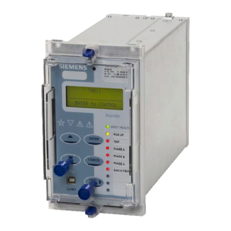
7SG163 Ohmega 300 Series SingleDEF
The copyright and other intellectual property rights in this document, and in any model or article produced from it
(and including any registered or unregistered design rights) are the property of Siemens Protection Devices
Limited. No part of this document shall be reproduced or modified or stored in another form, in any data retrieval
system, without the permission of Siemens Protection Devices Limited, nor shall any model or article be
reproduced from this document unless Siemens Protection Devices Limited consent.
While the information and guidance given in this document is believed to be correct, no liability shall be accepted
for any loss or damage caused by any error or omission, whether such error or omission is the result of
negligence or any other cause. Any and all such liability is disclaimed.
©2012 Siemens Protection Devices Limited
7SG163 Ohmega 300 Series
7SG163 Protection Relay
Document Release History
This document is issue 2012/01. The list of revisions up to and including this issue is:
Pre release
2010/02 Document reformat due to rebrand
2012/01 Figure 1 terminal numbering corrected
Software Revision History
7SG163 Ohmega 300 Series SingleDEF
Contents
1 Introduction. ......................................................................................................................................3
2 DEF Direction and Characteristic Angle. ........................................................................................3
2.1 DEF Schemes...........................................................................................................................4
2.1.1 DEF Direct Trip .................................................................................................................4
2.1.2 DEF POR..........................................................................................................................4
2.1.2.1 Current Reversal Guard................................................................................................4
2.1.2.2 CB Echo........................................................................................................................4
3 Relay Settings....................................................................................................................................5
3.1 DEF Auxiliary Protection Settings. ............................................................................................5
3.2 DEF Protection Status Inputs....................................................................................................5
3.3 DEF Protection Outputs............................................................................................................5
©2010 Siemens Protection Devices Ltd Chapter 12 Page 2 of 5
7SG163 Ohmega 300 Series SingleDEF
©2010 Siemens Protection Devices Ltd Chapter 12 Page 3 of 5
1 Introduction.
High resistance earth faults present difficulties to
impedance measuring elements since the
resistive coverage required can often extend
beyond the apparent impedance presented by
maximum load conditions. In those cases a
directional earth fault element can be used to
supplement the basic distance protection.
The design of the directional earth fault element
is based on similar techniques as used for
impedance measurement. The element is
voltage polarised deriving this by summating the
three phase to neutral voltages available in the
relay. The zero sequence current providing the
other input is derived from the fourth C.T. input
which must be connected as indicated in Figure
operation will occur for fault current occurring within the reverse operating zone. This can be seen in
gure 2.
directional relay. Operation will occur for angles in
DEF POR (Permissive
verreach Scheme).
is detected, and not cleared
ter a time delay.
his
ode is referred to as DEF DIRECT TRIP.
igure 2. DEF Operating Zones
1.
D2 EF Direction and Characteristic Angle.
The direction element can be set to operate in the forward or reverse direction. With the DEF Direction set to
forward, relay operation will occur for fault current occurring within the forward operating zone. With the relay set
to reverse
fi
The Characteristic Angle sets the maximum torque angle of the
the range +-85º of this setting, as shown in the diagram below:
The DEF element is normally used with a
signalling channel, operating as a simple high
speed directional comparison scheme in
conjunction with the remote end DEF. This is
referred to as a
O
If the signalling channel fails, however, a the
relay will carry out a time delayed backup trip if
the residual current
af
The element can also be used with no signalling
as a time graded directional IDMTL relay. T
m
F
Reverse
DEF
Forward DEF
DEF Char Angle
85°
85°
85°
85°
21
23
25
27
22
24
26
28
Ia
Ib
Ic
In
Fi
g
ure 1. Connection of residual current.
i
7SG163 Ohmega 300 Series SingleDEF
©2010 Siemens Protection Devices Ltd Chapter 12 Page 4 of 5
2.1 DEF Schemes
There are two active schemes for the relay.
2.1.1 DEF Direct Trip
In the DEF Direct Trip mode, the relay will trip on detecting an earth fault in the set direction. The DEF element is
time graded, and may be set to standard IEC or ANSI Curves or as a DTL element.
2.1.2 DEF POR
The other DEF scheme is DEF POR (permissive overreach). This is designed to be used in conjunction with a
signalling channel, to form a directional comparison scheme. When the DEF element operates it sends a
permissive signal, using the output contact assigned as Signal Send 2, to the remote end. In order to trip
instantaneously on DEF the relay must detect an earth fault on the forward direction and have received a signal to
Status Input Signal Receive 2 from the remote end. Obviously if the relays at both ends of the line detect a fault in
the forward direction, the fault must be within the line section, and tripping should be carried out instananeously.
In case the signalling channel fails, if the DEF element operates, and no signal is received from the remote end,
the relay will carry out a time delayed DEF back-up trip.
Additional logic is included within the DEF Scheme to ensure correct operation of the relay.
2.1.2.1 Current Reversal Guard
A current reversal guard is included to prevent incorrect tripping on parallel feeders.
Consider a fault at Point F on the parallel line system shown below:
Both Relay A and Relay B will detect earth fault current in the forward direction. Both DEF elements will operate,
permissive signals will be sent by both relays, and when these signals are received, Relays A and B will carry out
a DEF Aided Trip, isolating the fault.
Observing the direction of current flow, Relay C will also detect earth fault current in the forward direction , and
send a permissive signal to the remote end (Relay D). Relay D will detect earth fault current in the reverse
direction, and will not operate when the permissive signal is received from Relay C.
Now consider a situation, where the circuit breaker controlled by Relay B operates slightly before the circuit
breaker at A.
The direction of current seen by relays C and D will change, so Relay C will detect earth fault current in the
reverse direction, and relay D will detect earth fault current in the forward direction.
Under these circumstances, there is a “race condition” between the drop off of the Signal Send 2 output from
relay C and the operation of the forward DEF element at relay D.
If the DEF element at D operates before the Signal Send 2 from Relay C drops off, Relay D may mal-trip.
Thus, if the Circuit Breaker is closed, the relay does not detect fault current in the forward direction, a residual
voltage is present on the system,and a permissive signal has been received from the remote end, the Current
Reversal Guard logic is started. If the relay then detects a forward DEF it will enforce a time delay (the DEF
Current Reversal Reset) on the DEF Aided Trip to allow the remote end Signal Send 2 element to drop off, and
ensure stability of the protection.
2.1.2.2 CB Echo
The DEF POR scheme relies upon relays at both ends of the line detecting the fault. With the circuit breaker at
one end of the line open, the DEF element at one end cannot operate. Thus no permissive signal can be sent, so
the fault would be cleared after a time delay as a back-up trip for an in-zone fault.
Thus, if the local Circuit Breaker is open AND a permissive signal is received from the remote end, the relay will
send (or “echo”) a permissive signal back to the remote end. The duration of this permissive signal is set as the
POR CB Echo Pulse Width
Relay
D
Relay
C
S/Stn 1 S/Stn 2
Relay
B
Relay
A
F
7SG163 Ohmega 300 Series SingleDEF
©2010 Siemens Protection Devices Ltd Chapter 12 Page 5 of 5
3 Relay Settings
3.1 DEF Auxiliary Protection Settings.
DEF Protection - Allows the DEF Element to be enabled or disabled
DEF Active Scheme - Active scheme may be set as either DEF POR or DEF Direct trip. For more details on these
schemes see part 2.1 of this section.
DEF Char Angle - Defines the maximum torque angle of the DEF element. The relay will operate in the region
within ±85º of this angle.
DEF Direction - May be set forward or reverse. Normally set to look in the forward direction.
DEF IDMTL Setting - Defines the current pickup setting of the DEF element.
DEF IDMTL Char - Defines the characteristic used for the IDMTL element.
The choices are as follows:
IEC-NI, VI, EI, LTI,
ANSI-MI, VI, EI
Definite Time Lag (DTL)
DEF IDMTL Time Mult (IEC/ANSI) - Defines a time multiplication factor to be applied to the standard curve.
DEF IDMTL Delay (DTL) - Sets the DTL delay if the IDMTL characteristic is selected as DTL.
DEF IDMTL Reset - Allows the reser time of the element to be defined as Instantaneous (INST), Decaying, or a
definite time (0-60s)
DEF CRG Res OV Setting -This sets the level of residual overvoltage which must be present for the Current
Reversal Guard Logic to be activated.
DEF Current Rev Reset - Time delay fo rwhis the relay will restrain following a reversal in current direction. (See
part 2.1 of this section)
CB Echo Pulse Width - If the local CB is open, and a signal is received from the remote end this is the length of
time for which the Signal Send 2 output will be energised for. (See part 2.1 of this section)
3.2 DEF Protection Status Inputs
Block DEF – Energising this Status Input will inhibit the operation of the DEF element.
Signal Received 2 – This is energised by the operation of the remote end instantaneous.
Carrier Guard – This is designed to be energised by the failure of the signalling channel (i.e. from a channel not
healthy contact on the signalling equipment). When energised it wil prevent a DEF aided trip. The relay will be
able to carry out a time delayed back-up trip.
3.3 DEF Protection Outputs
The DEF Protection output operates for any DEF Operation (aided or back-up), and the DEF Aided Trip output
will only operate for an aided DEF trip.
Signal Send 2 – This will pick-up when the relay is in DEF POR mode and an Overcurrent starter has operated.

Other Siemens Relay manuals

Siemens 7SR242 Duobias Operating manual

Siemens

Siemens 7SR242 Duobias Operating manual

Siemens 3SK1120 Series User manual

Siemens

Siemens 3SK1120 Series User manual

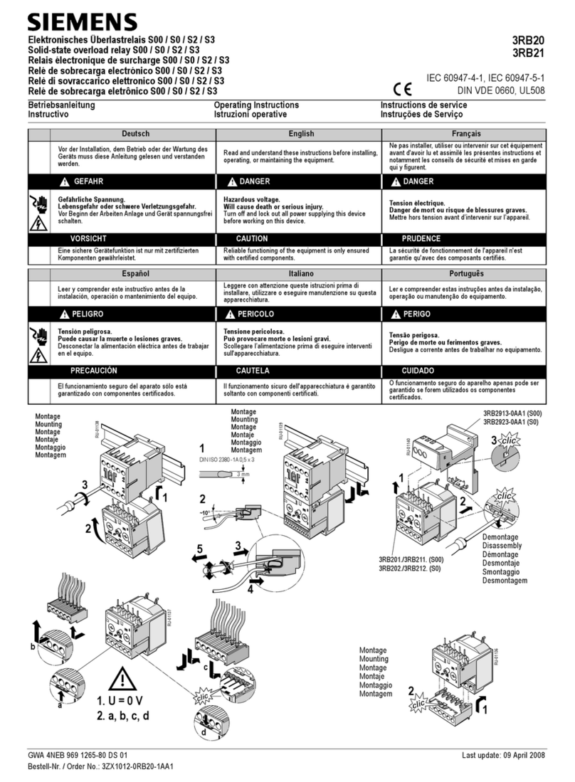
Siemens 3RB20 User manual

Siemens

Siemens 3RB20 User manual

Siemens SIPROTEC 7SJ81 User manual

Siemens

Siemens SIPROTEC 7SJ81 User manual

Siemens 7UG0 480-1IU20 User manual

Siemens

Siemens 7UG0 480-1IU20 User manual

Siemens 3VT9116-5GA40 User manual

Siemens

Siemens 3VT9116-5GA40 User manual

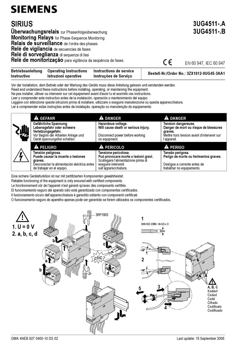
Siemens SIRIUS 3UG4511-.A User manual

Siemens

Siemens SIRIUS 3UG4511-.A User manual

Siemens 3RS1800 User manual

Siemens

Siemens 3RS1800 User manual

Siemens 7UG0 Series User manual

Siemens

Siemens 7UG0 Series User manual

Siemens 3US50 User manual

Siemens

Siemens 3US50 User manual

Siemens 3UG4 User manual

Siemens

Siemens 3UG4 User manual

Siemens SIRIUS 3RB3.3 Series User manual

Siemens

Siemens SIRIUS 3RB3.3 Series User manual

Siemens 3RP25 User manual

Siemens

Siemens 3RP25 User manual

Siemens 3RB12 User manual

Siemens

Siemens 3RB12 User manual

Siemens SIRIUS 3TX7680-1A User manual

Siemens

Siemens SIRIUS 3TX7680-1A User manual

Siemens SIRIUS 3RU5 36 B Series User manual

Siemens

Siemens SIRIUS 3RU5 36 B Series User manual

Siemens SIRIUS 3TK2841 User manual

Siemens

Siemens SIRIUS 3TK2841 User manual

Siemens 3RU7146 Series User manual

Siemens

Siemens 3RU7146 Series User manual

Siemens Solkor 7PG2114 User guide

Siemens

Siemens Solkor 7PG2114 User guide

Siemens SIRIUS 3UG4641-1 Series User manual

Siemens

Siemens SIRIUS 3UG4641-1 Series User manual

Siemens SIRIUS 8WD44.0-0EA2 User manual

Siemens

Siemens SIRIUS 8WD44.0-0EA2 User manual

Siemens SIRIUS 3RU5.4 User manual

Siemens

Siemens SIRIUS 3RU5.4 User manual

Siemens 3RV1976-3AP3 User manual

Siemens

Siemens 3RV1976-3AP3 User manual

Siemens 7SG13 Delta User manual

Siemens

Siemens 7SG13 Delta User manual

Popular Relay manuals by other brands

GST DI-9302E manual

GST

GST DI-9302E manual

Akuvox SR01 How to configure

Akuvox

Akuvox SR01 How to configure

GE P24DM Technical manual

GE

GE P24DM Technical manual

Mikro x20 user manual

Mikro

Mikro x20 user manual

LEGRAND 6 037 72 manual

LEGRAND

LEGRAND 6 037 72 manual

SMA Solar Technology MFR01-10 installation manual

SMA Solar Technology

SMA Solar Technology MFR01-10 installation manual

Pilz PNOZ XV1P operating instructions

Pilz

Pilz PNOZ XV1P operating instructions

Pilz PZA Series operating manual

Pilz

Pilz PZA Series operating manual

TIS VLC-6CH-5A installation manual

TIS

TIS VLC-6CH-5A installation manual

GE IFC66A instructions

GE

GE IFC66A instructions

Tekmar 003 Installation & operation manual

Tekmar

Tekmar 003 Installation & operation manual

Pilz PMUT X1P operating manual

Pilz

Pilz PMUT X1P operating manual

VAMP VAMP 59 Installation, operation and configuration instructions

VAMP

VAMP VAMP 59 Installation, operation and configuration instructions

ABB C6702 operating instructions

ABB

ABB C6702 operating instructions

Theben TR 608 top quick start guide

Theben

Theben TR 608 top quick start guide

Basler BE1-87T instruction manual

Basler

Basler BE1-87T instruction manual

Leviton EnOcean WSPAS-LV4 installation instructions

Leviton

Leviton EnOcean WSPAS-LV4 installation instructions

ABB RED670 Relion 670 series Commissioning manual

ABB

ABB RED670 Relion 670 series Commissioning manual

manuals.online logo
manuals.online logoBrands
  • About & Mission
  • Contact us
  • Privacy Policy
  • Terms and Conditions

Copyright 2025 Manuals.Online. All Rights Reserved.