Subject to technical changes
Table of contents
General Notes.............................................................................................................................................5
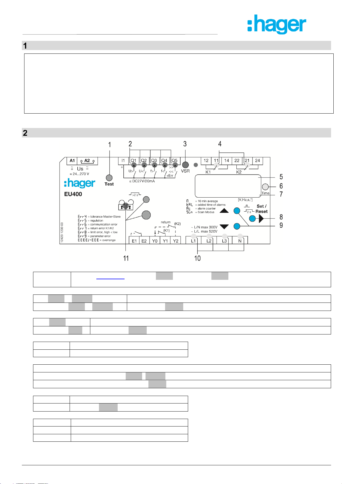
Display and controls..................................................................................................................................5
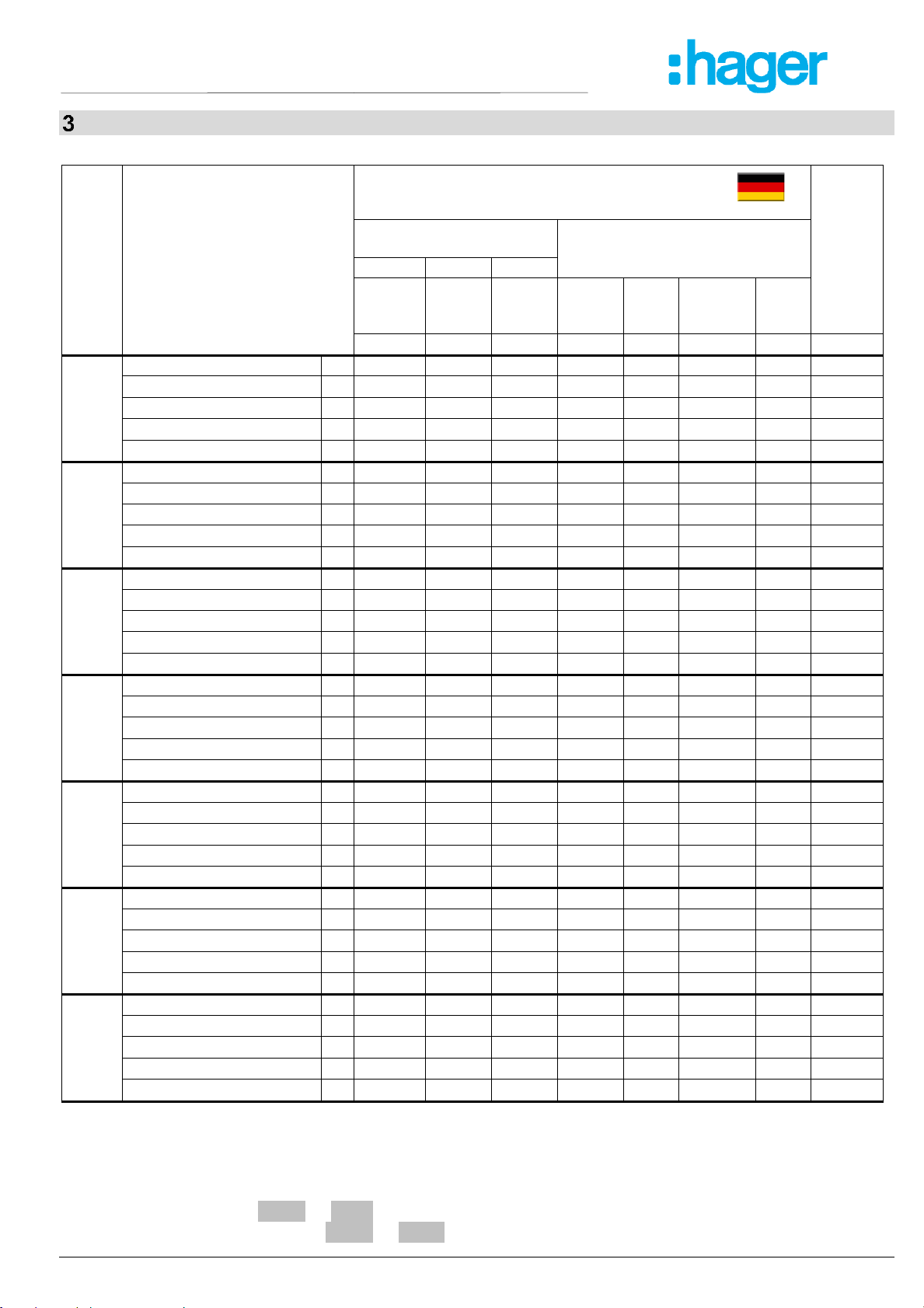
Default settings and firmware version, VDE-AR-N 4105 + BDEW .........................................................7
Default settings and firmware version, VDE-AR-N 4110 + 4120:2018-11..............................................9
Default settings and firmware version, TOR Erzeuger Typ A,B,C,D, VSE NA/EEA-NE7 CH 2020,
G98(83/2)+G99(G59/3), Synergrid C10 / C11..........................................................................................11
Application and brief description...........................................................................................................13
Summary of the functions.......................................................................................................................13
Connection diagrams ..............................................................................................................................14
8.1 1x PV, 1x section switch (VDE-AR-N 4105:2018-11)......................................................................14
8.2 1x PV, 2x section switch (VDE-AR-N 4105:2011) ...........................................................................15
8.3 Multiple PV with section switch and with a series-switched NC's as feedback contacts .................16
8.4 Multiple PV with section switch and with a parallel-switched closing contacts as feedback............17
8.5 1x PV, 1x section switch with nc/normally closed contacts (medium voltage VDE-AR-N 4110:2018-
11 / high voltage VDE-AR-N 4120:2018-11)....................................................................................18
8.6 Using integrated switches of PV and battery inverters according to DIN EN 62109 (VDE 0126-4).19
8.7 Generator operation, suppression of the feedback contacts ...........................................................20
Important information..............................................................................................................................21
Assembly..................................................................................................................................................21
Detailed description.................................................................................................................................22
11.1 Description of the connections.........................................................................................................22
11.2 Functional characteristics ................................................................................................................23
Commissioning........................................................................................................................................24
12.1 Program setup .................................................................................................................................24
12.2 Control chart Pr 2…6 and Pr 10…23 ...............................................................................................25
12.3 Control chart Pr 1 and Pr 7..............................................................................................................26
12.4 Description of the parameters..........................................................................................................27
12.5 Display mode (last decimal point off)...............................................................................................28
12.6 Menu mode (last decimal point on)..................................................................................................28
12.7 Configuration mode (last decimal point flashes)..............................................................................28
12.8 Switching conditions ........................................................................................................................29
12.9 Disengaging ratio.............................................................................................................................29
12.10 Monitoring of zero voltage ...............................................................................................................29
12.11 Test mode (timekeeping only activated and connected feedback contacts)....................................30
12.12 Alarm counter ..................................................................................................................................30
12.13 Cumulative alarm time (display in hours).........................................................................................30
12.14 Alarm memory .................................................................................................................................31
12.15 Standby counter and standby time ..................................................................................................31
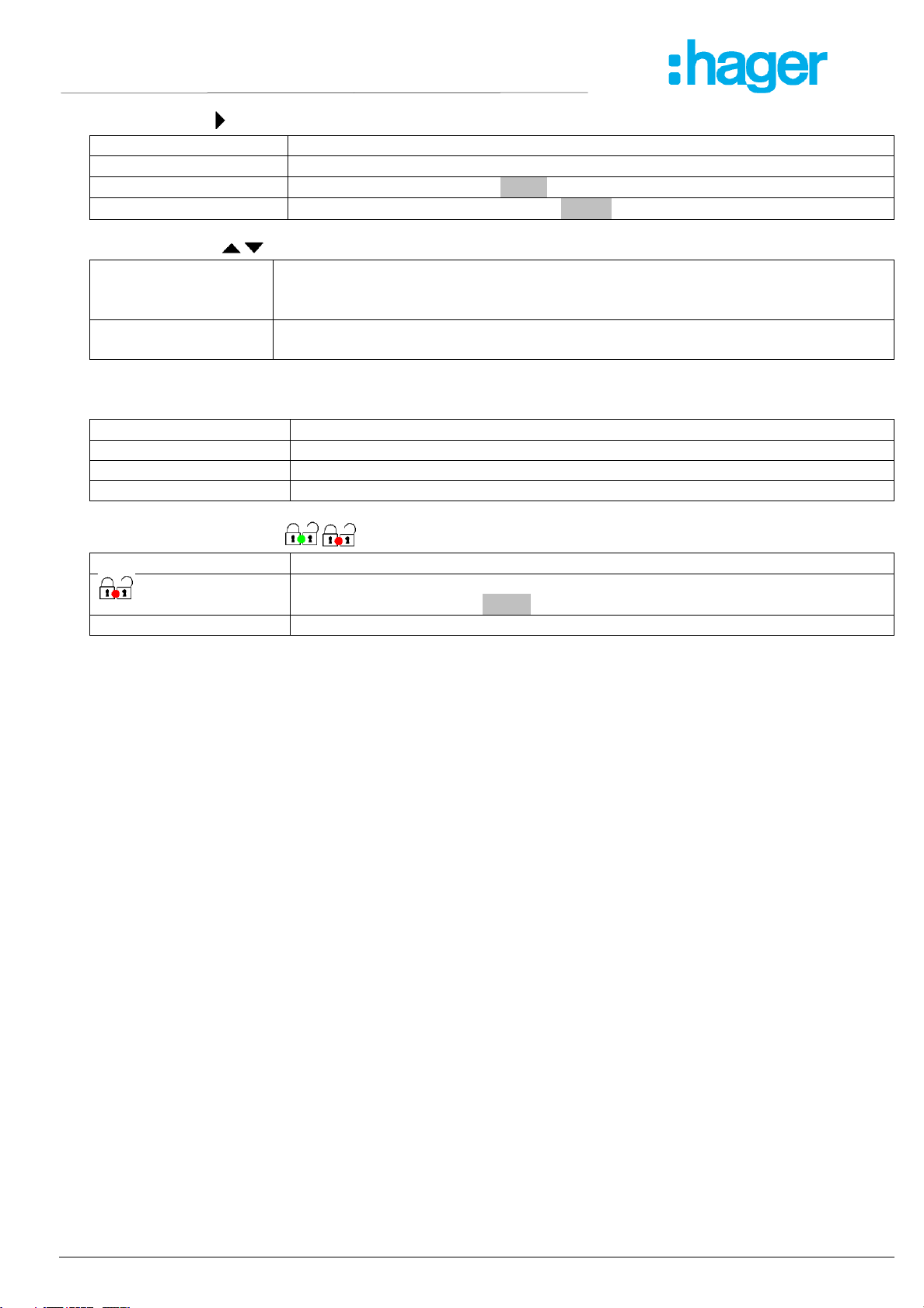
12.16 Code lock.........................................................................................................................................31
12.17 Sealing.............................................................................................................................................32