HKA TR-707 User manual

TR-707 ROM Expansion
This kit includes:
1x Pre-assembled PCB
1x Ribbon cable with IDC plug
1x 28-way IC socket
You will need:
- Fine tipped soldering iron & solder
- De-soldering pump or braid
- Phillips head screwdriver
- Wire strippers
www.hkadesign.org.uk july 2020
Installation Instructions
hkadesign
Installation
Remove the batteries from their compartment.
Back up your patterns rst if you don’t want to lose them!
1.
Remove the TEMPO knob and all of the slider caps, putting them somewhere safe, and
remove the 7x screws on the underside of the case.
2.
With the machine face down on a soft surface, lift off the bottom cover. Desolder the wires
going to the battery compartment, noting the positive and negative connections. Set the
bottom cover aside for now.
3.
Carefully disconnect the at ex ribbon going from the main board off to the cartridge
connector. To do so, pry the retaining clip away from the body of the connector, and the
ribbon will slide out. Temporarily remove the cartridge connector (2x screws) for better
access to the main board.
4.
Remove the screws that secure the main PCB assembly into the top case :
• 2x screws either side of the MIDI sockets on the back panel
• 2x screws in opposite corners of the circuit board assembly (top right and bottom left)
• 1x screw holding the ground wire to the panel board
5.
Lift the main PCB assembly out of the case, while disconnecting the two cables that join it
to the panel board. This is easiest done by holding the machine on end, with sockets facing
downwards, and the power button pressed in.
6.
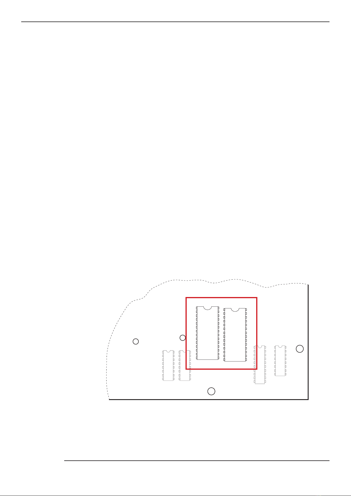
With the main board assembly out of the case, locate IC34 and IC35 in the front right-hand
corner of the PCB (both marked HN61256P). Carefully de-solder and remove them, and
solder the included chip sockets in place of IC35.
7.
40151
40174
IC32 IC33
40273
IC36
uPC624
IC37
HN61256
IC34
HN61256
IC35
Front right-hand corner of TR-707 main board

Installation
Plug the expansion board into the socket at IC35, ensuring that the pins are lined up correctly.8.
Separate, strip and tin the wires of the included ribbon cable (striped wire = 1) :
• Wires 1 to 8 should be separated to 3cm
• Wire 9 should be separated to 9cm
9.
On the panel board, locate the through-hole via directly above D313, and to the left of a
mounting screw (see diagram for Step 11). Using a sharp knife, carefully scrape away the
solder mask on it to reveal the copper underneath. Apply a blob of solder to it.
10.
Solder the wires from the ribbon cable to locations on the panel board as shown below.
Once this is done, secure the ribbon cable down with a piece of insulation tape.
11.
D312
CN303
35 25
IC302
CN302
24 14
IC301
D350
D313
1357
2468
9
D315 D314
D310
D309 D308
D307
D324 D323 D322 D321
Solder side of panel board
Stripe
Reinstall the main PCB assembly in the top case, reconnecting the two cables that join it to
the panel board. Like the disassembly, this is easiest done with the machine on end.
Replace the screws that secure the board assembly in the top case, that you removed
in Step 5, also replacing the ground wires.
12.

Installation
Route and fold the new ribbon cable to the expansion board, and plug it into the header
connector. It is keyed and can only be inserted one way round.
13.
Replace the cartridge connector and reconnect the at ex ribbon.
Re-solder the wires to the battery compartment.
14.
Replace the bottom cover, 7x case screws, TEMPO knob and slider caps.15.
View looking into top case
Sound Banks
The ROM Expansion has 8x sound banks, which are listed below.
The bank is selected by holding down one of the rst 8 step keys while powering on the
machine. The setting will be remembered and recalled at next power-on.
The ROM Expansion kit will replace all of the sounds, except for the last two: crash + ride on
the TR-707, quijada and star chime on the TR-727. A future add-on board will allow these
to be switched as well.
1 2 3 4 5 6 7 8
BASS DRUM SNARE DRUM LOW TOM MID TOM HI TOM RIMSHOT COWBELL
9
1 2 3 4 5 67 8 9
727707 808 909 Linn
Drum LM-1 DMX
707
+
727
Table of contents
Popular Control Unit manuals by other brands

Festo
Festo Compact Performance CP-FB6-E Brief description

Elo TouchSystems
Elo TouchSystems DMS-SA19P-EXTME Quick installation guide

JS Automation
JS Automation MPC3034A user manual

JAUDT
JAUDT SW GII 6406 Series Translation of the original operating instructions

Spektrum
Spektrum Air Module System manual

BOC Edwards
BOC Edwards Q Series instruction manual

KHADAS
KHADAS BT Magic quick start

Etherma
Etherma eNEXHO-IL Assembly and operating instructions

PMFoundations
PMFoundations Attenuverter Assembly guide

GEA
GEA VARIVENT Operating instruction

Walther Systemtechnik
Walther Systemtechnik VMS-05 Assembly instructions

Altronix
Altronix LINQ8PD Installation and programming manual


