HKS CAMP2 User manual

INSTRUCTION MANUAL
E84511‑K00070‑00
2008/1
Ver.3‑1.01
HK S E L E C T R O NIC S T E C H NO L O G Y


Product
Use
Application
Part Number
Remarks
CAMP2 (Computerized Automobile Multi Player 2)
Automobile Data Monitor
Any vehicle that operates on a DC12V negative ground
48001-AK001
・This product does not include a monitor.
・A monitor must be purchased separately; a 7 inch or larger monitor is recommended.
NOTICE
−1−
This manual assumes that you have and know how to use the tools and equipment necessary
to safely perform service operations on your vehicle. This manual assumes that you are familiar
with typical automotive systems and basic service and repair procedures. Do not attempt to carry
out the operations shown in this manual unless these assumptions are correct. Always have access
to a factory repair manual. To avoid injury, follow the safety precautions contained in the factory
repair manual.
HKS CAMP2 is a device to monitor vehicle information on the vehicle's on-board screen. This
product can be connected to an on-board screen equipped the video input terminal or a car
navigation monitor.
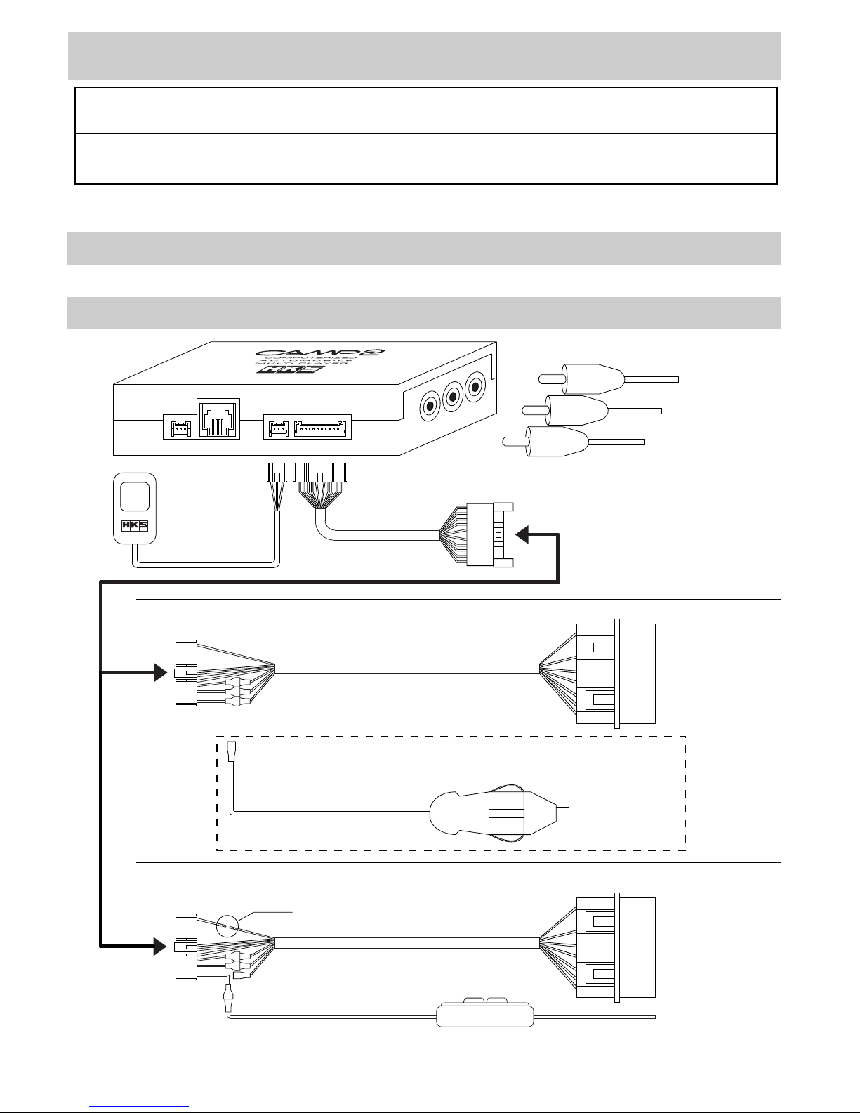
●Simple Installation
The installation can be coupler-on to the ISO14230 CONSULT connector.
Also, using an optional Nissan CONSULT harness or an F-CON connector cable enables
CAMP2 to function on a variety of vehicles.
●24 Types of Displayable Data
Up to 6 of the following 24 data items can be displayed on the screen at one time:
Speed, Engine RPM, Water Temperature, Ignition Timing, A/F Correction Value, A/F Learning
Value, Intake Air Volume, Intake Temperature, Throttle Position, Intake Manifold Pressure,
O2 Voltage, Airflow Voltage, Fuel Injection time, Battery Voltage, Fuel Efficiency, Horsepower,
A/F Value, Knocking Value, I/F Boost Pressure, I/F Water Temperature, I/F Oil Temperature,
I/F Oil Pressure, I/F Fuel Pressure, I/F Exhaust Temperature (EGT).
●Past Function
Up to 4 of the following 6 calculations can be displayed on the screen at one time: elapsed
time, driving distance, average speed, fuel consumption, average fuel consumption, and fuel
cost.
●Graph
Up to 6 data parameters can be graphed on a time-based axis, and can be data-logged for
up to 10 minutes.
●Analog Meter Indicator
Up to 3 data parameters can be displayed in an analog meter style display on the screen.
Meter panel color can be configured in white, black, or red.
●Digital Meter Indicator
Up to 6 data parameters can be displayed numerically at the same time.
●F-CON Connection
F-CON S / SZ / SA / iS / V Pro can be connected to the CAMP2 unit, and data from the F-CON
can be displayed on the screen.
●F-CON Map Edit Function
F-CON S / SZ / SA / iS setting data can be monitored and edited when connected to CAMP2.
Unique settings can be made based on engine specification, such as exhaust type or intake
type.

−2−
Notice ……………………………………………
Index ……………………………………………
Safety Instructions ……………………………
Parts List ………………………………………
Names & Functions …………………………
1.Names ……………………………………
2.Items on the screen ……………………
Installation ……………………………………
1.Disconnecting the Battery Terminal ……
2.Wiring ……………………………………
3.Mounting …………………………………
4.After Installation …………………………
Confirmation after Installation ………………
Operation ………………………………………
1.Operation Outline ………………………
2.SET UP Mode ……………………………
3.PAST Mode ………………………………
4.GRAPH Mode ……………………………
5.ANALOG Mode …………………………
6.DIGITAL Mode …………………………
7.F-CON Mode ……………………………
INDEX
1
2
3
4
5
5
6
7
7
7
10
11
11
12
12
14
18
19
21
24
26
・This manual indicates items you need to pay attention in order to install this product safely
and lists precautions to avoid any possible damage and/or accidents.
・For any lost, defective and/or damaged parts, contact the dealer to order.
・HKS will not be responsible for any damage caused by incorrect installation and/or use or use
after modification and/or dismantling of this product.
・HKS will not be responsible for any damage caused by removing vehicle's in/exterior, electric
parts or modification for installation.
・This product was designed based on installing it onto a factory vehicle or a vehicle using other
HKS products. The performance and/or safety cannot be guaranteed if this product was
installed onto other inapplicable vehicles.
・This product works only with a vehicle with DC12V negative ground.
・The specifications of this product are subject to be changed without notice.
・This manual is subject to be revised without notice.
・The user must keep this manual.
●I/F Unit Connection
Connecting an HKS I/F Unit (P/N 44008-AK011) to the CAMP2 will allow for connected sensor
data to be displayed on the screen.
●Warning Function
When actual data exceeds or falls short of set value, the driver is notified with audible and
visual alerts.
●Peak Hold Function
The data peak values can be displayed on the screen.
Optional Parts List ……………………………
Maintenance …………………………………
Troubleshooting ………………………………
Product Specifications ………………………
28
28
29
29

−3−
SAFETY INSTRUCTIONS
WARNING
・Make sure to work on the vehicle in a well-ventilated area to prevent possible
explosion or a fire.
・Do not mount the unit where distracts driving to avoid possible accident.
・Do not install this product to a vehicle with DC24V negative ground. It may cause
a fire.
・Make sure to remove the cable from the negative terminal of the battery to avoid
possible damage to other electronics parts and/or a fire caused by a short circuit.
・Make sure to hold the connectors' lock when removing them to avoid possible
damage to other electronics parts and/or a fire caused by disconnection or a short
circuit.
・Stop using the product if any unusual situation is noticed. Consult the dealer
immediately.
・Do not stare at the monitor while driving; this may cause car accidents. Please
park the car in a safe area when operating the product.
・Make sure to work on the vehicle without children to prevent them from swallowing
small parts.
CAUTIONS
・Do not install this product by yourself unless you have and know how to use the tools
and equipment necessary to safely perform service operations on your vehicle.
・Do not modify, disassemble, and/or remodel the product and attached parts to avoid
any damage to the unit and/or harness.
・Handle the parts with caution at all times.
・To avoid possible malfunction and damage to the engine, install the unit away from
excessive heat, water/moisture, and/or dust.
・Make sure all connections and wiring are not disconnected, short circuited, or incorrect.
If so, it may cause an electric shock, burn out, or damage to the vehicle.
・Use the supplied splice as instructed in the manual to avoid any damage to the vehicle
by misconnection.
・If the product or the vehicle with the product does not perform properly, consult the
dealer immediately.
・Do not try to repair the product by yourself. Consult the dealer.
・When unusual noise, smell, and/or vibration are noticed while driving, deal with them
as instructed in the user's manual.
・Do not test the product on a public road.
・If this product is connected using an external input, the vehicle's factory navigation
and/or audio may not function while this product is in use.

−4−
◆Daily maintenance on the vehicle is the responsibility of the owner.
◆This manual shows a typical installation. Actual installation may vary depending on
the vehicle application.
◆When removing factory parts, refer to the factory manual.
◆Do not lose and/or damage any removed parts.
◆Make sure all connections and wiring are correct.
◆Make sure to use appropriate tools to tighten bolts and nuts. Do not over-tighten
bolts and nuts.
◆Make sure not to disconnect the vehicle's wiring while installing this product. It may
cause damage to the vehicle and/or this product.
◆If this product is operated around the passenger seat or rear seat area while driving,
use an adaptor to display the audio and video properly on the vehicle monitor.
(The adaptor is not included in this product.)
・If the TV's video on the screen becomes distorted, or the picture from this product
does not appear clearly, this does not necessarily mean that the product is damaged.
To solve these symptoms, disconnect and reconnect the AV cable or turn off/on this
product.
・Since CAMP2 uses an infrared remote controller, keep the controller and receiver
away from exposure to the direct rays of the sun. If the controller and/or the receiver
are exposed directly to the sun, the controller may not function properly.
PARTS LIST
Instruction Manual
Double-sided Tape
Remote Controller Receiver
CAMP2
1
1 1 1 1
1 1
3
2 3 4
5 8
9 10 11 12
1.5m
Power Socket Harness
1
OBD2 Harness
0.3m
Power Supply Harness AV Cable
1 1
1.0m
6 7
1
Remote Controller
Velcro Tape
Black
2.0m
Tie Wrap
2
Black
13
Splice
14
1
1.0m
2.0m
車種別適合表
本書はHKS CAMP2を取付けるための適合表です。
製品の取付けは取扱説明書をお読みください。
取付ける車両の車種・年式・型式・エンジン型式・通信タイプ
コネクタ位置をよく確認して取付けを行ってください。
E
8
4
5
1
1
−
K
0
0
0
4
0
−
0
0
2
0
0
8
年
2
月発行
V
e
r
.
3
‑1
.
0
1
HKSELECTRONICSTECHNOLOGY
Application List
1
15
1
Caution Sheet
Black
取扱説明書
取付けは、必ず専門業者に依頼してください。
取付前及びご使用前に必ずお読みになってください。
本書はお読みになった後も、本製品の側に置いてご活用ください。
ご使用中にわからないことや、不具合が生じた際に便利です。
E84511‑K00030‑00
2008年2月発行
Ver.3‑1.01
HKSELECTRONICSTECHNOLOGY
製品使用上の注意
●本製品は車載モニターに車両情報を表示する装置です。
カーナビゲーションユニットの外部入力機能を使用して本製品
を接続した場合、本製品の映像を表示している間、カーナビ
ゲーション機能およびオーディオ機能などが使用できなくなる
場合があります。
これはカーナビゲーションユニットの仕様となりますので、
あらかじめご了承ください。
●本製品を車載モニターに接続した状態で、まれにTV映像が
ちらつく・TV映像に本製品の映像が薄く表示されるなどの症
状が発生する場合がございますが、本製品の異常ではあり
ません。
上記のような症状が発生した場合、本製品を使用しない時
はAVケーブルを外すか電源を切って頂けますよう、お願い
致します。
●本製品は操作用に赤外線リモコンを使用しております。
このためリモコンおよびリモコン受光部に直射日光などの
強い光が当たっていると、リモコン操作ができない場合が
あります。
直射日光などを避け設置して頂けますよう、お願い致します。
●運転中、ドライバは本製品の操作および画面の注視をしない
でください。
ドライバが操作する場合は、安全な場所に車を停止して
から行ってください。
わき見運転は事故の原因となります。
48002-AK004 48002-AK003
Relay Harness

−5−
NAMES & FUNCTIONS
1.Name
1. Relay Harness Connector
Front
2. Remote Control Receiver Connector
3. F-CON Connector
4. I/F Unit Connector
Right 5. Video Signal Output Terminal (Yellow)
6. Audio Signal Output Terminal (White)
7. Audio Signal Output Terminal (Red)
8. Slide Switch
9. USB Connector
Left
●CAMP2 Main Unit
1.Relay Harness Connector
This is to connect the relay harness to the OBD2 harness.
2.Remote Control Receiver Connector
This is to connect the remote controller receiver.
3.F-CON Connector
This is to connect CAMP2 to F-CON using a modular cable.
4.I/F Unit Connector
This is to connect a meter harness to use HKS I/F Unit (P/N 44008-AK011) with CAMP2.
5.Video Signal Output Terminal (Yellow)
This is to connect the yellow AV cable to output video to the screen.
6.Audio Signal Output Terminal (White)
7.Audio Signal Output Terminal (Red)
This is to connect the white and red AV cable to output audio to the vehicle's on-board monitor.
8.Slide Switch
Slide the switch to the right when using the optional Nissan CONSULT harness.
(The default switch position is on the left to connect the OBD2 harness.)
9.USB Connector
Connect the CAMP2 unit to a PC using a USB cable. (This function will be enabled soon.)

−6−
●CAMP2 Remote Controller
1.PEAK Button
2.Directional Arrow
Buttons (4)
3.ENTER Button
4.SELECT Button
5.BACK Button
2. ITEMS ON THE SCREEN
Item
SPEED
REV
WATER
IGN
CORRECT
LEARN
AIR
IN_TEMP
THROTTLE
IN_MAIN
O2_VOLT
AIRFLOW
INJECTOR
BATTERY
ECO
POWER
A/F
KNOCK
IF BOOST
IF WATER
IF OIL_T
IF OIL_P
IF FUEL_P
IF EXT_T
NONE
Description
Speed
Engine RPM
Water Temperature
Ignition Timing
A/F Correction Value
A/F Learning Value
Intake Air Volume
Intake Air Temperature
Throttle Position
Intake Manifold Pressure
O2 Voltage
Airflow Voltage
Injection Time
Battery Voltage
Fuel Efficiency
Horsepower
A/F Value
Knocking Value
I/F Unit's Boost Pressure
I/F Unit's Water Temperature
I/F Unit's Oil Temperature
I/F Unit's Oil Pressure
I/F Unit's Fuel Pressure
I/F Unit's EGT
−
№
1
2
3
4
5
6
7
8
9
10
11
12
13
14
15
16
17
18
19
20
21
22
23
24
25
Unit
SI
km/h
rpm
℃
CA
%
%
g / s
℃
%
×100kPa
V
V
ms
V
km / L
kW
−
−
×100kPa
℃
℃
×100kPa
×100kPa
℃
−
USA
mph
rpm
゜F
CA
%
%
g / s
゜F
%
PSI
V
V
ms
V
m / USG
HP
−
−
PSI
゜F
゜F
PSI
PSI
゜F
−
1.PEAK Button
Press this button to show the peak value.
2.Directional Arrow Buttons (4)
Press these directional arrow buttons to
relocate the pointer or change the value.
3.ENTER Button
Press this button to set the edited value or
setting.
4.SELECT Button
Press this button to select the menu.
5.BACK Button
Press this button to go back to the previous
screen.
Can only be displayed when an F-CON
is connected, and the F-CON iS is
connected to the OBD2 port.
These items can be shown when F-CON
& A/F Knock Amp. are connected.
Remarks
These items can be shown when the I/F
Unit is connected.

−7−
INSTALLATION
(1) Disconnect the negative terminal from the battery.
1.Disconnecting the Battery Terminal
2.Wiring
Warning
To the vehicle's
on-board monitor.
AV Cable
OBD2 Harness
Power Socket
Harness
*For non Nissan vehicle, connect the White/Black wire of the
power socket harness to the pink wire of the OBD2 harness.
To the power
socket.
CAMP2
Main Unit
White Connector
Red Connector
White/Black Wire
To the vehicle's
OBD2 connector.
Splice to the
ignition wire.
Yellow Wire
Pink Wire
Power Supply
Harness
OBD2 Harness
BMW
Standard
Vehicle
●This manual shows a typical installation. Actual installation may vary depending on
the vehicle application.
●This product is for vehicles that operate on a DC12V negative ground. Do not install
onto any vehicle operates on a DC24V; it may cause a fire.
Connect the OBD2 Cable.
Remote
Controller
Receiver
Relay
Harness
To the vehicle's
OBD2 connector.
・For BMW vehicles, wiring of the OBD2 harness should be conducted as shown below.
For BMW, cut & insulate this wire.
(See the section 4 in next page.)
*Connect the yellow wire of the power supply harness to
the pink wire of the OBD2 harness.

−8−
OBD2 Harness
Power Socket
Harness
Power Supply
Harness
Splice to the constant
power supply wire.
Do not connect when the
self-diagnosis connector
is not available.
Yellow Wire
Yellow Wire
Black Wire
White Wire
White/Black Wire
Pink Wire
Wiring for BMW
White Connector
6 7 10
10
Cut the #10 wire.
Insulate with
electrical tape.
6 7 10
(1) Connect the vehicle's on-board monitor and CAMP2 using the AV cable.
Advice
・If the on-board monitor needs a special connector or another harness available from the
monitor's manufacturer, this must be used.
(2) Connect the remote controller receiver harness to CAMP2.
(3) Connect the relay harness to CAMP2.
(4) Connect the white connector of the OBD2 to the relay harness.
Advice
・For non Nissan vehicles, connect the White/Black wire of the car
plug harness to the pink wire of the OBD2 harness.
・If a 12V power socket the cigar socket is not available, connect the
power supply harness to the pink wire of the OBD2 harness.
Splice these to the line that outputs 12V while ignition is on.
(See page 10 for splicing.)
・For BMW, cut the wire inserted into #10 of the white connector.
(See the illustration on the right.) Insulate both ends of the cut wire
with electrical tape to prevent shorts. Connect the power supply harness
to the pink wire of the OBD2 harness. Splice these to the line that
outputs 12V while ignition is on. (See page 10 for splicing.)
(5) Connect the red connector of the OBD2 harness to the vehicle's self-diagnosis connector.
(6) Insert the battery into the remote controller.
(For replacing the button battery, see Maintenance in page 29.)
●F-CON Wiring
<When the vehicle's self-diagnosis connector (OBD2 port) is unused (available)>
(1) Follow the procedure (1) to (6) above.
(2) Connect the F-CON connector of CAMP2 to the option port of the F-CON unit with the modular
cable.
NOTE
・The modular cable is not included. Use the optional F-CON connecting cable or a 6 pin - 4
core straight modular cable available at a hardware store.
(3) Connect the OBD2 harness as shown below.
・Connect the white/black wire of the power socket harness to the pink wire of the OBD2 harness.
Connect the black wire of the power socket harness to the white wire of the OBD2 harness.
・Connect the yellow wire of the OBD2 harness to the power supply harness. Splice these to
the line that outputs 12V while ignition is off (constant power supply). (See page 10 for splicing.)
(When the vehicle's self-diagnosis connector is being used (NOT available))

−9−
Option Port
・F-CON S/SZ/SA
・F-CON Vpro
・F-CON iS
・F-CON Option Port List (The port locations vary depending on the type of F-CON.)
●I/F Unit Wiring
MAIN
HARNESS
WATER TEMP
OIL TEMP
EXT.TEMP
OIL PRESS
BOOST
& VACUUM
FUEL PRESS
I/F Unit
Main Harness
Power Supply
Harness
Meter Harness
#1
White
Orange
Red
Black
Connect sensor harnesses.
(Engine Room)
(Interior)
※If the meter harness #1 length is
too short to reach CAMP2, use the
optional meter harness #3(1.0m) to
connect CAMP2 and the meter
harness #1.
: To Constant Power Supply wire
: To IG wire
: To illumination wire
: Body ground

−10−
3.Mounting
Strip the cover 5mm.
Twist wires together.
Insulate with plastic
tape.
Stake the wires
using a splice.
One Side of Velcro Tape
Another Side of Velcro Tape
To interior To interior
(Mounting CAMP2)
・Follow the procedure 2. (1) - (6) in page 8 for wiring.
・Connect the meter harness #1 of I/F Unit to the I/F Unit Connector of CAMP2.
Advice
・Read the included manual for I/F Unit wiring instructions.
・If the meter harness #1 length is too short to reach CAMP2, use the longer meter harness #3
(1m) available separately.
・I/F Unit does not include sensors and sensor harnesses. Harnesses necessary for wiring
must be purchased separately. (See the optional parts list.)
●Splicing
①Strip 5mm of the wire cover for wiring as shown
to the right.
②Connect another wire to the uncovered portion
twisting wires together.
③Crimp the twisted wires using a splice.
④Cover the splice and wires with electrical tape to
insulate.
(1) Mount the CAMP2 main unit using the Velcro tape on the area where the controller receiver
is reachable and away from exposure to the direct rays of the sun.
(2) Mount the controller receiver using the double-sided tape on the area away from exposure
to the direct rays of the sun.
(3) Mount the remote controller using the Velcro tape on the area away from exposure to the
direct rays of the sun.
Advice
・Install the unit away from excessive heat, water, moisture, and/or dust. Do not mount the
unit on or in front of the air bag.
・Remove any dirt, dust, and/or oil from the area the unit is going to be mounted.

−11−
4. After Installation
(1) Reinstall any factory parts that were removed.
(2) Reconnect the negative terminal to the battery.
Another side of
Velcro Tape
One side of
Velcro Tape
To interior
Double-sided Tape
Controller Receiver
To interior
(Mounting Remote Controller) (Mounting Receiver)
Confirmation after installation
Check
Check
・Check the following after the installation process is complete.
(1)Check the following before starting the engine:
(2)Start the engine and check the following:
Check item
Make sure all wiring is done correctly.
Make sure all installed components do not come in contact with other parts.
Make sure harnesses are secured so that they do not disturb driving.
Make sure all removed factory parts are reinstalled.
Make sure the negative cable terminal is securely connected to the battery.
Make sure a battery is set to the remote controller.
Advice
・Do not raise the engine RPM right after starting the engine. Let it idle and warm up properly.
Check item
Make sure the installed parts are not hitting each other.
Make sure there is no excessive stress on harnesses.
Make sure there are no loose parts after the engine is stopped.

−12−
1.Operation Outline
OPERATION
GRAPH
・Time axis & Digital
meter indicator display.
・Data logging of 6 items
for up to 600 seconds.
GRAPH SELECT
・GRAPH1-6
・ENDLESS LOG
S
E
L
E
C
T
B
A
C
K
ANALOG
・3analog meters
Switch by the enter
button.
・1analog meter + 6 digital
meters
ANALOG SELECT
・ANALOG 1 - 6
・METER COLOR
・DIGITAL METER
S
E
L
E
C
T
B
A
C
K
S
D
F
PAST
・6 items can be shown.
TIME (Elapsed Time)
DISTANCE (Distance Driven)
SPEED (Average speed)
FUEL (Fuel consumption)
ECO (Average fuel efficiency)
COST (Fuel cost)
・Channel is selectable from
A to D.
・Under channel A, the automatic
measurement is available in
SET UP Mode.
[MENU]

−13−
SET UP
(Setting menu1)
TYPE
ECO CORRECT
SPEED CORRECT
POWER CORRECT
CAR WEIGHT
GAS COST
AUTO PAST
WARNING
ALL REST
▼
DIGITAL
・6digital meters
Switch by the
enter button.
・3digital/bar graph
DIGITAL SELECT
・DIGITAL1-6
S
E
L
E
C
T
B
A
C
K
F-CON
・Fuel injection volume
correction map A/B
・Ignition timing correction
map A/B
Editing the Correction Map
E
N
T
E
R
B
A
C
K
(Setting Menu 2)
▲
X OFFSET
Y OFFSET
UNIT
TITLE BACK
MENU BACK
EDIT RED
EDIT GREEN
EDIT BLUE
S
D
F
: Manufacturer name
: Fuel efficiency correction value
: Speed correction value
: Horsepower correction value
: Vehicle weight
: Gasoline cost
: Auto PAST function ON/OFF
: Warning setting
: Reset
: Go to the next page.
: Go back to the previous page.
: Adjusting the video position - left
: Adjusting the video position - up
: Unit of measure - Switch SI unit to
USA unit.
: Menu background color
: Each mode background color
: Custom background color
(adjust red)
: Custom background color
(adjust green)
: Custom background color
(adjust blue)

−14−
2.SET UP MODE
・SET UP MODE to configuring CAMP2 to work with your vehicle.
・Use this mode when using CAMP2 for the first time or after a reset.
<Setting Items>
●TYPE(Vehicle Setting)
Select the type of vehicle.
Refer to the application list for setting.
TOYOTA1 TOYOTA2 NISSAN1 NISSAN2 NISSAN3 MAZDA HONDA
BMW CAN DAIHATSU SUZUKI SUBARU MITSUBISHI2 MITSUBISHI1
●ECO CORRECT(Fuel efficiency correction value)
This item is to correct the fuel efficiency. The set value range is from 0 to 5000, in increments
of 10. The default value is 1000.
・ Setting & Calculating ECO CORRECT
・Setting based on the application list
Input the fuel efficiency correction value from the application list.
・ Calculating the set value from actual gas volume.
①Temporarily use the default ECO CORRECT value of "1000".
②Fill up the fuel tank on level ground.
③Set PAST mode to CLEAR & START.
④Drive until the fuel tank becomes nearly empty, and fill up the tank at the same
location in ②.
⑤Calculate the actual ECO CORRECT value from the fuel volume and the FUEL
value in PAST mode.
Actual ECO CORRECT Set Value = Fuel Volume ÷FUEL value ×1000
<Setting>
・In the menu, use the direction button in the controller to select "SET UP", and press the
ENTER. SET UP menu is separated to 2 screens.
・Move the left cursor to the item for setting using the direction button in the controller, and
press the ENTER button. When the white character or the white number is turned to orange,
edit it using the direction button in the controller.
・After editing the setting, press the ENTER. When the edit is made, the orange character
or the orange number is turned to white.
・If more edit is needed, repeat the procedure above.
※When the following setting is necessary, change "UNIT" in the second screen of the SET
UP menu from "SI" to "USA" (See "UNIT" in page 17) before starting editing.

−15−
●SPEED CORRECT (Speed correction value)
This item is to correct the speed value when the vehicle is equipped with tires of different size
from factory spec, or when there is a variance between the actual driving distance and the value
of DISTANCE in PAST mode. The set value range is from 0.1 to 199.9(%) in increments of 0.1.
The default value is 100.0.
・Setting & Calculating SPEED CORRECT
Change the default value "100.0" to the value calculated in (a) or (b) below.
(a) Calculating the set value for the vehicle equipped with tires of different size from factory spec:
SPEED CORRECT (Speed correction value) =
Outer diameter of the upgraded tire / Outer diameter of the factory tire ×100
(Example)
Size of the upgraded tire : 235/45-17
Outer diameter of the upgraded tire : (235 x 45 ÷100 x 2 + 17 x 25.4) x 3.14 = 2019.962mm
Size of the factory tire : 205/55-16
Outer diameter of the factory tire : (205 x 55 ÷100 x 2 + 16 x 25.4) x 3.14 = 1984.166mm
SPEED CORRECT (Speed correction value) = 2019.962 ÷1984.166 x 100 = 101.804 = 101.8
*Round to the second decimal point.
(b) When there is a variance between the actual driving distance and the value of DISTANCE
in PAST mode:
Calculate the speed correction value by measuring the actual driving distance as follows:
・Do not measure on a public road.
・Do not burn out or otherwise spin tires without contact with pavement while measuring.
・Measure while the vehicle is driven in a straight line.
Measurement needs a certain distance to figure out the actual driving distance.
SPEED CORRECT (Speed correction value) =
Actual driving distance ÷the indicated DISTANCE value ×100
(Example)
Actual driving distance : 1.0 mile Indicated DISTANCE value : 1.1 mile
SPEED CORRECT (Speed correction value) = 1.0 ÷1.1 x 100 = 90.909 = 90.9
*Round to the second decimal point.
●POWER CORRECT (Horsepower correction value)
This item is to correct the value when there is a variance between the actual horsepower on
the chassis dynamometer and the values of POWER in each mode. The set value range is
from 1.0 to 199.9(%) in increments of 1. The default value is 100.0.
・Setting & Calculating POWER CORRECT(HP correction value)
Change the default value "100.0" to the value calculated below.
POWER CORRECT (HP correction value) = Actual HP ÷Indicated HP x 100
(Example)
Actual HP : 268HP Indicated HP : 276HP
POWER CORRECT (HP correction value) = 268 ÷276 x 100 = 97.101 = 97
*Round to the first digit.
(Example)
Fuel volume : 12.0 USG FUEL value : 8.2USG
ECO CORRECT Set Value = 12.0 ÷8.2 x 1000 = 1463.4 = 1460
*Round to the first digit.
⑥Change ECO CORRECT value from "1000" to "1460

−16−
ITEM
INJECTOR
BATTERY
ECO
POWER
A/F
KNOCK
IF BOOST
IF WATER
IF OIL_T
IF OIL_P
IF FUEL_P
IF EXT_T
DESCRIPTION
Injection Time
Battery Voltage
Real-Time Fuel Economy
Horsepower
A/F Value
Knocking Value
I/F Unit Boost
I/F Unit Water Temperature
I/F Unit Oil Temperature
I/F Unit Oil Pressure
I/F Unit Fuel Pressure
I/F Unit EGT
ITEM
SPEED
REV
WATER
IGN
CORRECT
LEARN
AIR
IN_TEMP
THROTTLE
IN_MANI
O2_VOLT
AIRFLOW
DESCRIPTION
Speed
Engine RPM
Water Temperature
Ignition Timing
A/F Correction Value
A/F Learning Value
Intake Air Volume
Intake Air Temperature
Throttle Position
Intake Manifold Pressure
O2 Voltage
Airflow Voltage
●CAR WEIGHT (Vehicle weight)
This item is to enter the vehicle's weight. The set value range is from 10 to 2500kg in increments
of 10(kg). The value of the CAR WEIGHT must be the total number of the following:
①The listed weight on the registration form.
②Total weight of the driver/passengers at the time of calculation.
③Weight of half the fuel tank representing total weight of fuel, oils, coolant, etc.
●GAS COST (Fuel cost/USG)
This item is to enter the fuel cost. The set value range is from US$1.50 to 10.0 in increments
of US $0.01. COST in PAST mode is calculated from this value. The default value is US$1.50.
●AUTO PAST (Automatic past function)
This item is to activate PAST mode (Channel A) automatically when the ignition is turned on.
AUTO PAST ON : Every time the ignition is turned on, Channel A of PAST mode will
automatically reset and starts new measurements.
AUTO PAST OFF: PAST mode is activated manually.
●WARNING
This item is for the warning setting of each item under the following conditions:
TYPE (Item)
VALUE (Value)
DIRECTION (Range)
FUNCTION (Function)
: Select from 24 items.
: Set the warning value.
: Set the warning alarm to activate if the actual value exceeds or
falls short of set value.
: Set the warning alarm on or off.
●ALL RESET
This function resets all entered values and settings back to default.
Select YES to initialize, NO to not initialize.
Advice
・After initializing an ALL RESET, reapply initial settings in SET UP mode.
●▼(Go to the next page)
Press the ENTER button to go to the next page.

−17−
Menu's background
color
Change to USA
●▲(Go back to the previous page)
Press the ENTER button to go back to the previous page.
●X OFFSET (Screen position adjustment - Left)
Use this if the screen position is offset horizontally to one side.
The adjustment range is from 0-32, in increments of 1. The default setting is 0.
●Y OFFSET (Screen position adjustment - Upper)
Use this if the screen position is offset vertically to one side.
The adjustment range is from 0-32, in increments of 1. The default setting is 0.
●UNIT (Unit of Measure)
Select the unit from USA unit or SI unit. The default is SI unit.
USA Unit - Distance: mile, Speed: mph, Fuel volume: USG, Temperature: °F,
Fuel Efficiency: m/USG, Pressure: PSI, Horse Power: HP
SI Unit - Distance: km, Speed: km/h, Fuel volume: L, Temperature: °C,
Fuel Efficiency: km/L, Pressure: x 100kPa, Horse Power: kw
(※Other items use common units.)
●TITLE BACK (Menu's background color)
Select the color of Menu's background. The default color is blue.
BLUE ⇔BLACK
●MENU BACK (Each item's background color)
Select the color of the items' background. The color selected here is the color of all items.
The default color is Blue.
Blue Carbon Black Original
Advice
・The background color of the menu can be selected in TITLE BACK.
・Under ORIGINAL, an original color can be made by setting EDIT RED / GREEN / BLUE.
●EDIT RED / EDIT GREEN / EDIT BLUE (To make an original color for MENU BACK.)
Under this item, an original color can be made by editing the level of each color.
The level can be selected from 0 to 31. The default levels of 3 colors are 0.
Advice
・Select "ORIGINAL" in MENU BACK to use the original color for the background.

−18−
3.PAST MODE
・Under this mode, commuting routes can be compared, or driver-specific information can be
monitored.
・6 measurements/calculations can be displayed on the screen at one time: TIME (Elapsed Time),
DISTANCE (Driving distance), SPEED (Average speed), FUEL (Consumed fuel volume),
ECO(Average fuel efficiency), and COST (Fuel cost). Real-time fuel efficiency is shown as
a bar graph on the bottom right of the screen.
・Measurements are available in 4 channels (A to D).
・In the channel A, if AUTO PAST ON is selected, every time the ignition is turned on, the data
will be automatically reset, and measurement are started anew.
Current channel
Select Start, Stop,
or Clear.
Fuel efficiency is
shown here.
<Setting>
・Select [PAST] in the menu using the controller's directional arrow buttons. Press ENTER.
・Select a channel from A to D using the controller's directional arrow buttons.
Advice
・All 4 channels can measure at the same time.
・The encircled letter tells which channel is currently active on the screen. To change the
channel, press the red cursor.
<Operation>
・Start Measurement
Select "START" using the controller's directional arrow buttons. Press ENTER.
・Stop Measurement
Select "STOP" using the controller's directional arrow buttons. Press ENTER.
・Clear Data
Select "CLEAR" using the controller's directional arrow buttons. Press ENTER.
Advice
・In DISTANCE (Driving distance), when the value goes over 3107 mile, it resets to 0.0 mile.
・In FUEL (Consumed fuel volume), when the value goes over 132 USG, it resets to 0.0 USG.
・In TIME (Time passage), when the value goes over 99:59:59, it resets 00:00:00.
・In COST (Fuel cost), when the value of FUEL becomes 0.00 USG, the value of COST
automatically becomes 0.00.
・The correct value of the average fuel efficiency and the average speed may not be shown
for a while after starting the PAST mode.
Table of contents