HLA BALE KNIFE Series User manual

HORST WELDING
8082 Rd 129
Listowel, ON N4W 3G8
Canada
519-291-4162
1-866-567-4162
Fax 1-519-291-5388
www.horstwelding.com
!
Do not attempt to operate the equipment without thoroughly
reviewing this manual for safe and proper operation.
Rev 171019 HA00100.BK Bale Knife Series.040518
Operator’s Manual
Keep this manual with the machine at all times
PRINTED IN CANADA
BK Series Bale Knife
BK48LF, BK60LF, BK72LF
!
CAUTION
Operational Hazard
Personal Protection Equipment
(PPE) is required when operating
or maintaining this machine.
SNL00001

2
Notes

3
Introduction � � � � � � � � � � � � � � � � � � � � � � � � � � � 4
Intended Use . . . . . . . . . . . . . . . . . . . . . . . . . . . .5
Parts List. . . . . . . . . . . . . . . . . . . . . . . . . . . . . . . .5
California Proposition 65 . . . . . . . . . . . . . . . . . . .5
General Information � � � � � � � � � � � � � � � � � � � � 5
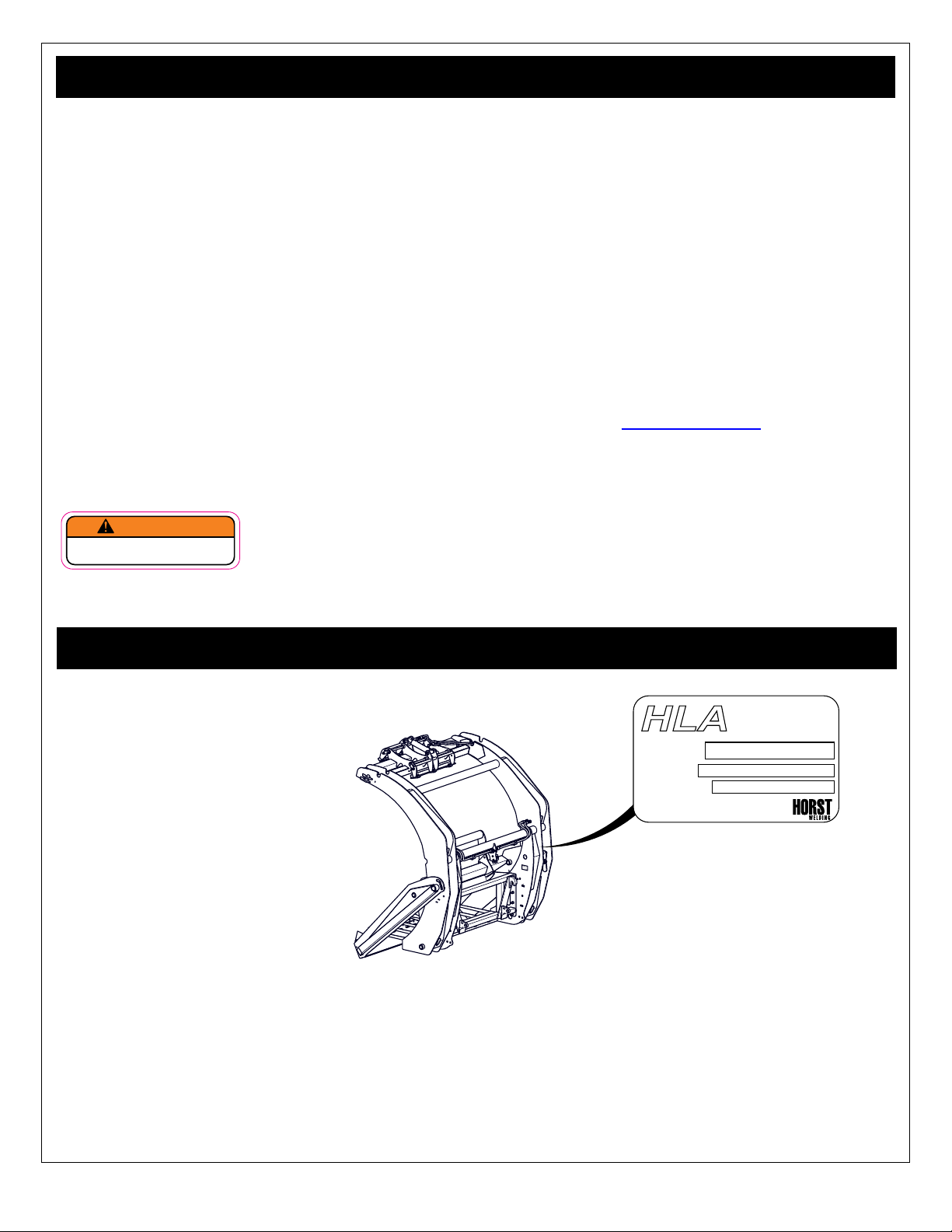
Serial Number Location � � � � � � � � � � � � � � � � � 5
Safety � � � � � � � � � � � � � � � � � � � � � � � � � � � � � � � � 6
Safety Messages . . . . . . . . . . . . . . . . . . . . . . . . .6
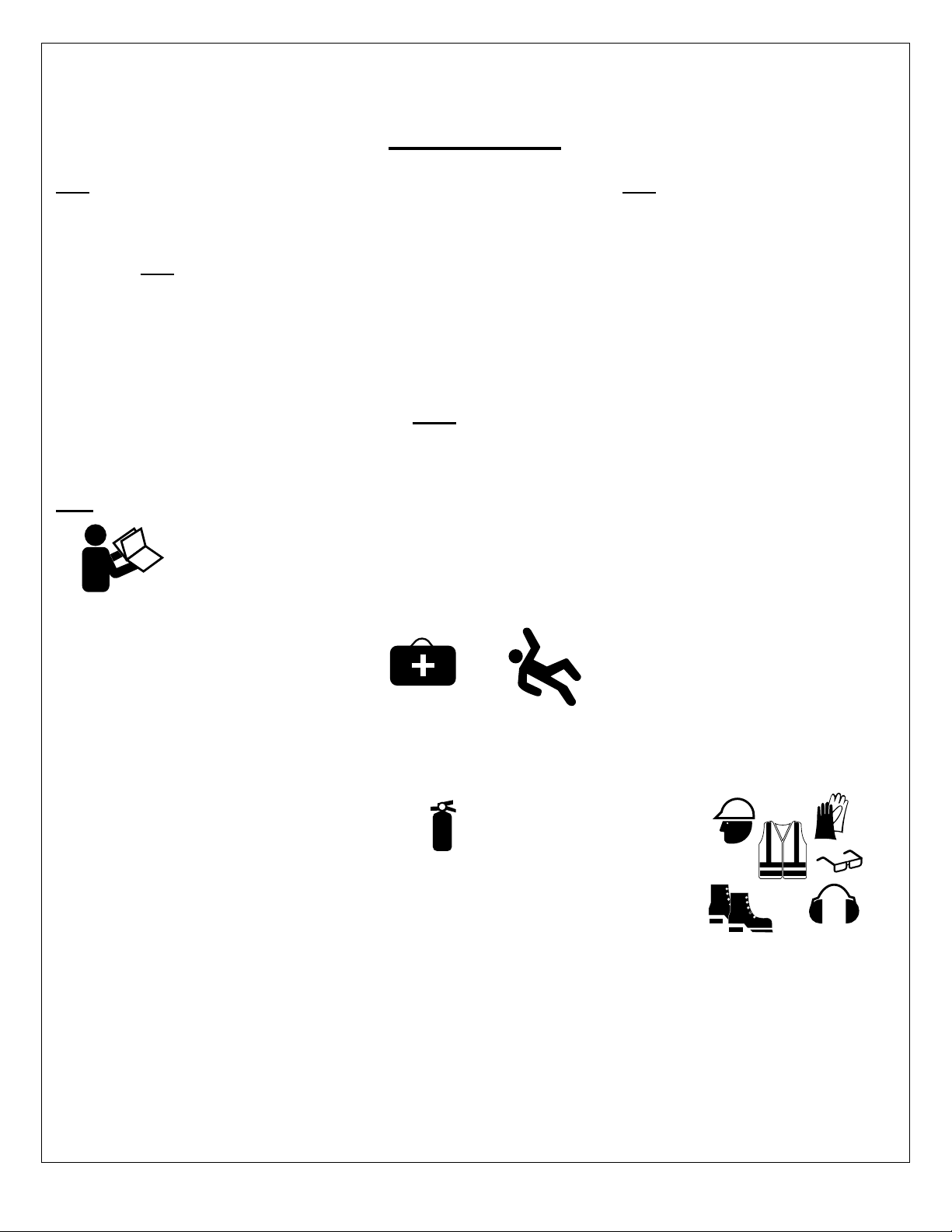
Accident Prevention . . . . . . . . . . . . . . . . . . . . . . .7
Safety Guidelines . . . . . . . . . . . . . . . . . . . . . . . . .8
Safety Training . . . . . . . . . . . . . . . . . . . . . . . . . . .8
Preparation . . . . . . . . . . . . . . . . . . . . . . . . . . . . . .9
Operation Safety. . . . . . . . . . . . . . . . . . . . . . . . . .9
Maintenance Safety . . . . . . . . . . . . . . . . . . . . . . .9
Storage Safety . . . . . . . . . . . . . . . . . . . . . . . . . . .9
Hydraulic Safety . . . . . . . . . . . . . . . . . . . . . . . . .10
Safe Work. . . . . . . . . . . . . . . . . . . . . . . . . . . . . .10
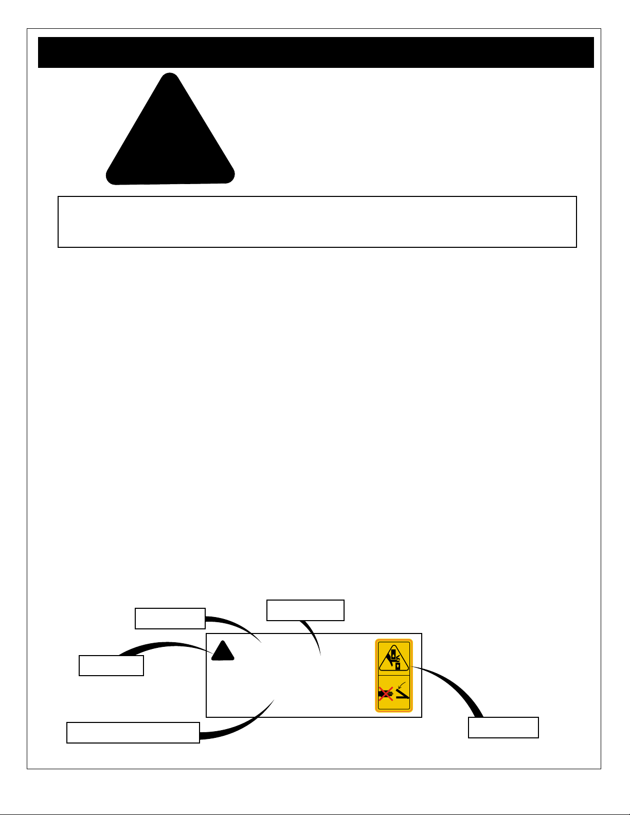
Safety Labels � � � � � � � � � � � � � � � � � � � � � � � � � 11
Safety Label Descriptions. . . . . . . . . . . . . . . . . . 11
If labels need to be replaced: . . . . . . . . . . . . . . . 11
Safety Label Layout . . . . . . . . . . . . . . . . . . . . . .12
� � � � � � � � � � 13
. . . . . . . . . . . . . . . . . . . . . . . . . . .13
Dimensions. . . . . . . . . . . . . . . . . . . . . . . . . . . . .14
Inspection� � � � � � � � � � � � � � � � � � � � � � � � � � � � 14
Components and Features � � � � � � � � � � � � � 15
BK Series Bale Knife Components. . . . . . . . . . .15
Product Features . . . . . . . . . . . . . . . . . . . . . . . .16
Bumper Assembly . . . . . . . . . . . . . . . . . . . . . . . . . . 16
Wrap Undresser . . . . . . . . . . . . . . . . . . . . . . . . . . . 16
Storage Stand . . . . . . . . . . . . . . . . . . . . . . . . . . . . . 16
Wrap Grabber . . . . . . . . . . . . . . . . . . . . . . . . . . . . . 16
Check Valve . . . . . . . . . . . . . . . . . . . . . . . . . . . . . . 17
Kverneland Tines . . . . . . . . . . . . . . . . . . . . . . . . . . 17
Hardened Cutting Knives . . . . . . . . . . . . . . . . . . . . 17
Initial Setup � � � � � � � � � � � � � � � � � � � � � � � � � � 18
Hydraulics . . . . . . . . . . . . . . . . . . . . . . . . . . . . .18
Mount the Bale Knife . . . . . . . . . . . . . . . . . . . . .19
Remove Shipping Clamps . . . . . . . . . . . . . . . . . . . 19
Adjust the Bumper (BK60 & 72 only) . . . . . . . . .19
Adjust the Undresser . . . . . . . . . . . . . . . . . . . . .20
Test . . . . . . . . . . . . . . . . . . . . . . . . . . . . . . . . . . .20
Field Operation � � � � � � � � � � � � � � � � � � � � � � 21
Operation Safety Checklist . . . . . . . . . . . . . . . . .21
Prepare. . . . . . . . . . . . . . . . . . . . . . . . . . . . . . . .21
Material. . . . . . . . . . . . . . . . . . . . . . . . . . . . . . . .21
Mount the Blade Knife . . . . . . . . . . . . . . . . . . . .22
Quick Attach . . . . . . . . . . . . . . . . . . . . . . . . . . . . . . 22
Hydraulics . . . . . . . . . . . . . . . . . . . . . . . . . . . . . . . . 22
Operating . . . . . . . . . . . . . . . . . . . . . . . . . . . . . .23
Safety . . . . . . . . . . . . . . . . . . . . . . . . . . . . . . . . . . . 23
Bale Handling . . . . . . . . . . . . . . . . . . . . . . . . . . . . . 23
Feeding the Bale . . . . . . . . . . . . . . . . . . . . . . . . . . 23
Storage � � � � � � � � � � � � � � � � � � � � � � � � � � � � � � 24
Storage Safety Checklist . . . . . . . . . . . . . . . . . .24
Placing in Storage: . . . . . . . . . . . . . . . . . . . . . . .24
Service & Maintenance � � � � � � � � � � � � � � � � 25
Maintenance Safety Checklist . . . . . . . . . . . . . .25
General Maintenance . . . . . . . . . . . . . . . . . . . . .25
Hydraulic Oil . . . . . . . . . . . . . . . . . . . . . . . . . . . .25
Lubrication: . . . . . . . . . . . . . . . . . . . . . . . . . . . . 26
Grease: . . . . . . . . . . . . . . . . . . . . . . . . . . . . . . . . . 26
Cutting Knives: . . . . . . . . . . . . . . . . . . . . . . . . . 27
Sharpening . . . . . . . . . . . . . . . . . . . . . . . . . . . . . . . 27
Replacing . . . . . . . . . . . . . . . . . . . . . . . . . . . . . . . . 27
Kverneland Tines: . . . . . . . . . . . . . . . . . . . . . . . 27
Replacing . . . . . . . . . . . . . . . . . . . . . . . . . . . . . . . . 27
Bolt Torque Table . . . . . . . . . . . . . . . . . . . . . . . .28
Trouble Shooting � � � � � � � � � � � � � � � � � � � � � 29
Accessories � � � � � � � � � � � � � � � � � � � � � � � � � 30
Index � � � � � � � � � � � � � � � � � � � � � � � � � � � � � � � � 31

4
Thank you for purchasing your new HLA BK Series Bale Knife � Your HLA Bale Knife has been designed and
manufactured to give you many years of dependable service. BK Series unique design helps to increase productivity by
The BK Bale Knife
The BK Bale Knife series comes complete with seven replaceable Kverneland tines, which allow you to spear or scoop
all in one solution for bale handling.
Features include a proprietary hydraulic wrap grabbing system that automatically grips the wrap and bale netting
preventing it from dropping into the feeder or mixer.
The hardened tool steel cutting knives (eight on the BK48 & 60, nine on the BK72) deliver a consistent cut, and stay
sharp. If any knife is damaged, the bolt-on feature allows for easy replacement of a single knife without needing to replace
the entire row.
The upward slicing design allows for bales to be sliced not only into feeders and mixers, but also as little as 6” above the
ground, making it ideal for operation in tight areas with low overhead space.
HLA BK Series Bale Knife requires that you or any other person, who
will be assembling, operating, maintaining or working with this product, are required to read and completely understand
the information and instructions contained in this manual.
If anyone does not fully understand every part of this manual, please obtain further assistance by contacting the dealer
from which this product was purchased or by contacting Horst Welding with the information listed on the cover of this
manual.
Keep this operators manual available for reference by the operator and to pass on to new owners and or operators .
This manual covers models: BK48, BK60 and BK72
BK72

5
Model Number _________________________________________________________
Serial Number _________________________________________________________
The purpose of this manual is to assist you in safely operating and maintaining your HLA BK series Bale Knife in a safe
manner. Read this manual carefully to obtain valuable information and instructions that will help you achieve safe and
dependable service. The illustrations and data used in this manual were current at the time of printing, but due to possible
engineering and or production changes, this product may vary slightly in detail. Horst Welding reserves the right to update
In this manual the HLA BK Series Bale Knife series may be referred to as Bale Knife, BK, implement or machine.
References may be made to the power unit: which is the engine-driven machine to which this product is attached.
OPERATOR ORIENTATION - The directions left, right, front and rear, as mentioned throughout this manual, are
determined when sitting in the power unit driver’s seat and facing in the direction of travel
round bales, slicing bale net and plastic wrapping and feeding round bales.
The parts lists and hydraulic schematics for this product can be found online. Visit hlaattachments.com and click on the
PARTS tab to be directed to our online parts catalogue.
You may see a warning label like the following:
WARNING
Cancer and Reproductive Harm
www.P65 Warnings.ca.gov
This warning is required by California Proposition 65 (Prop 65), which is meant to notify California residents of exposures
to Prop 65-listed chemicals. For more information go to ‘www.P65Warnings.ca.gov.’
ATTACHMENTS
HLA
SERIAL #
MODEL #
CAPACITY
MANUFACTURED BY
MADE IN CANADA
H
L
A
The serial number for your HLA BK series Bale Knife is located on the middle back right side of the main bale shear
frame.
Please record your serial number here as a handy reference. In case of warranty issues, your dealer will ask for the serial
to verify your warranty.

6
!
This Safety Alert Symbol means:
ATTENTION!
BECOME ALERT!
YOUR SAFETY IS INVOLVED!
manual. When you see this symbol, read and understand the message, be alert to the potential
hazard in the message. Follow the instructions in the safety message.
Throughout this manual, the terms DANGER, WARNING, CAUTION and IMPORTANT are used to indicate the degree of
hazard to personnel if proper safety procedures and guidelines are not followed. The appropriate term for each message
has been selected using the following guide-lines:
In the owners manual, when a hazard is present you will see a safety message box. The box may contain:
• The safety alert symbol,
• The safety term
• The safety hazard
• The safety hazard explanation
When applicable you may also see the appropriate safety label displayed with the message, as shown below.
!
WARNING
Pinch Point Hazard
The top rail and beam form a poten-
tial pinch point, be aware of where
hands and feet are while adjusting
the top rail. SL00002
Safety Label
Safety Alert
Safety Hazard
Safety Term
Safety Hazard Explanation
The safety information given in this manual does not replace any safety codes, insurance needs, government and local laws.
DANGER - Indicates an imminently hazardous situation that, if not avoided, will result in death
or serious injury, and includes most extreme situations typically for implement com-
ponents which, for functional purposes, cannot be guarded.
WARNING - Indicates a potentially hazardous situation that, if not avoided, could result in death
or serious injury, and includes hazards that are exposed when guards are removed.
It may also be used to alert against unsafe practices.
CAUTION - Indicates a potentially hazardous situation that, if not avoided, may result in minor or
moderate injury. It may also be used to alert against unsafe practices.
IMPORTANT - Indicates a situation that could result in damage to the implement or other property.

7
ACCIDENTS CAN BE PREVENTED WITH
YOUR HELP!
YOU are responsible for the SAFE operation and maintenance of your implement. YOU must ensure that you and anyone
else who is going to use, maintain or work around the implement be familiar with the work and maintenance procedures
and related SAFETY information contained in this manual. This manual will take you step-by-step through your working
day and alerts you to all good safety practices that should be used.
Remember, YOU are the key to safety. Good safety practices not only protect you but also the people around you. Make
familiar with the recommended maintenance and work procedures and follow all the safety precautions. Most accidents
can be prevented. Do not risk injury or death by ignoring good safety practices.
The best accident prevention is a careful operator�
Horst Welding and your dealer ask that YOU be that careful, responsible equipment operator�
YOU ARE THE KEY TO SAFETY:
•Familiarize yourself, and anyone else
who will operate, maintain, or work around
this product, with the safety and operation
information contained in this manual.
• Read and understand the safety labeling which
appears on the implement.
•
the need arise and know how to use it.
• Pay attention to the job at hand. Do not let your mind
lose concentration on what you are doing. No accident
prevention program can be successful without the
wholehearted cooperation of the person who is
directly responsible for the operation of the implement.
•
the need arise and know how to use it.
• Reduce the risk of injury or death by following all
safety precautions and by using good safety practices.
• Accidents can to be prevented: that prevention will
come from equipment operators who accept their
complete responsibility and anticipate the results of
their actions.
• Never exceed the limits of the implement. Safety of
the operator and safe operation are the main concerns
in designing a safe product, however ignoring
a accident which could have been prevented.
•Do not allow riders on the implement,
loaded or empty.
•Do not operate this implement under the
• Be responsible for the SAFE operation and
MAINTENANCE of YOUR implement.
• Wear appropriate personal protective equipment
(PPE). This list includes but is not limited to:
• Hard hat
• Heavy gloves
• Hearing Protection
• Protective foot wear
• Protective eye wear
• Safety Vest

8
Safety of the operator and bystanders is one of the chief concerns in developing and designing equipment. However,
every year many accidents occur which could have been avoided by a few seconds of thought and a more cautious
approach to handling equipment.
You, the operator, can avoid many accidents by observing the following precautions in this section. To avoid personal
injury or death, study the following precautions and insist those working with you, or for you to follow them.
and accident prevention are dependent upon the awareness, concern, and proper training of personnel involved in the
operation, transport, maintenance, and storage of the implement. Refer also to safety messages and operation instruction
to the implement.
1. In order to provide a better view, certain illustrations
in this manual may show an assembly with a safety
device removed. However, equipment should never be
used in this condition. Keep all safety devices in place,
if removal becomes necessary for repairs, replace the
device prior to use.
2. Replace any safety label or instruction sign that is
unreadable or is missing. Location of safety signs is
indicated in this manual.
3. Never use alcoholic beverages or drugs which can
hinder alertness or coordination while using this
implement. Consult your doctor about using this
implement while taking prescription medications.
4. Under no circumstances should young children be
allowed to work with this implement.
5. This implement is dangerous to persons unfamiliar
with its operation. Do not allow persons to use or
assemble this unit until they have read this manual
and have developed a thorough understanding of the
safety precautions and of how it works. Review the
safety instructions with all users annually.
6. If the elderly are assisting with work, their physical
limitations need to be recognized and accommodated.
Assistants should be a responsible, properly trained
and physically able person familiar with machinery
and trained in this implement’s operations.
7. Never exceed the limits of the implement. If its ability
to do a job, or to do so safely, is in question - DON’T
TRY IT.
8. Do not modify the implement in any way. Unauthorized
may impair the function and life of the implement.
• Train all new personnel with the instructions
alongside the implement. Be certain only a properly
trained and physically able person will use the
machinery.
• Working with unfamiliar equipment can lead to
careless injuries. If this implement is used by any
person other than yourself, or is loaned or rented, it is
the implement owner’s responsibility to make certain
that the operator, prior to using:
• Reads and understands the operator’s manuals.
• Is instructed in safe and proper use of the implement
• If the elderly are assisting with the work, their
physical limitations need to be recognized and
accommodated.
the implement. An untrained operator exposes himself and bystanders to possible serious injury or death.
• Operators or maintenance personnel who are not
fully able to read and understand this manual should
not operate or work on the implement:
• Make certain that all operators and maintenance
personnel have complete understanding of the full
and exact contents of this manual and safety labeling.
• ALL information contained in this manual and labeling
on the implement must be conveyed CLEARLY and
FULLY, in order to be able to operate safely and
knowledgeably.
• Review the implement and instructions regularly with
existing workers.

9
1. Inspect machine for shipping damage. If damage does
exist, do not use. Notify your dealer immediately to
have damaged parts replaced or repaired.
2. Inspect all fasteners that they are not lose or missing.
Ensure fasteners are torqued according to the torque
chart at the back of this manual
3. If traveling at night, ensure provincial, state and local
laws lighting requirements have been met.
4. Ensure that all applicable safety decals are installed
and legible.
5. Personal protection equipment (PPE) including hard
hat, safety glasses, safety shoes, and gloves are
recommended during assembly, installation, operation,
adjustment, maintaining, repairing, removal, cleaning,
clothing or jewelry to be around equipment.
6. PROLONGED EXPOSURE TO LOUD NOISE MAY
CAUSE PERMANENT HEARING LOSS!
Gas diesel powered equipment can often be noisy
enough to cause permanent, partial hearing loss. We
recommend that you wear hearing protection on a full-
time basis. Noise over 85dB on a long-term basis can
cause severe hearing loss. Noise over 90db adjacent
to the Operator over a long-term basis may cause
permanent, total hearing loss.
7. When not attached to the power unit, ensure the unit
is secured to prevent movement.
1. NEVER allow helpers or bystanders under or near the
machine.
2. Inspect all fastening devices, do not use if worn or
damaged.
3. Make sure that everyone is clear before moving
the machine. NEVER position yourself between the
towing unit and the machine.
4. Do not permit riders while transporting this machine.
5. Where possible, avoid operating near ditches,
embankments and holes.
6. Lifting heavy loads overhead while traveling may
decrease your power units stability. Loss of control
could lead to serious personal injury.
7. Check the power units owner manual to determine if a
counter weight is required.
8. Tractors should have a reliable ROPS (roll over
protection system) installed and always buckle the
seat belt.
9. Always be aware of overhead hazards such as power
lines, shed roof overhangs and tree branches.
1. Store the unit in an area away from human activity.
2. Do not allow children to play on or around the stored
machine.
3. Store the unit in a dry, level area. Cover if stored
outside.
4. Guard any sharp corners.
5. Ensure components and safety features are not
damaged and in good condition before storing the
machine. Make repairs now to be ready for the
following session.
6. Secure the machine to prevent unwanted movement.
1. Good maintenance is your responsibility, follow the
maintenance schedule. Poor maintenance is an
invitation to trouble.
2. Follow good shop practices.
• Keep service area clean and dry.
• Be sure electrical outlets and tools are properly
grounded.
• Use adequate light for the job at hand.
3. Never work under or around the machine unless it is
blocked and chocked securely.
4. Use personal protection equipment (PPE) such as
eye, hand and hearing protectors.
5. Never adjust, service, clean or lubricate the machine
unit.
6. Ensure hardware is torqued according to the torque
chart at the back of this manual.

10
1. Make sure that all the components in the hydraulic
system are kept in good condition and are clean.
2. Before applying pressure to the system, inspect
for leaks at all components, and that lines, hoses ,
connections and couplings are not damaged and leak
free.
3. Do not attempt any makeshift repairs to the
clamps or cements. The hydraulic system operates
under extremely high pressure. Such repairs will
fail suddenly and create a hazardous and unsafe
condition.
4. Wear proper hand and eye protection when searching
for a high pressure hydraulic leak. Use a piece of
wood or cardboard as a backstop instead of hands to
isolate and identify a leak.
5. If injured by a concentrated high-pressure stream of
Serious infection or toxic reaction can develop from
6. Relieve pressure on hydraulic system before
maintaining or working on system.
7.
Not all work spaces are the same, but the principles
presented here can be applied to any work space.
Survey the work site, remove debris and make note of
nearby or overhead obstructions, knowing your work area
will make the job easier and safer.
Where possible, avoid operating near ditches,
embankments and holes.
Be aware of:
Bystanders or any one not directly involved with the
work are only allowed outside of the work area, minimized
hazards.
Workers helping the operator must wear the appropriate
PPE and must always make eye contact with the operator
before entering the work area. Unauthorized Workers or
bystanders are not allowed in the work area. Hazards are
present.
Operator, do not operate the machine outside of the
operator area.

11
Safety labeling is an important part of the overall safe use of the implement. Safety labeling alerts and warns against
potential injury or death, and is important to follow these points to help keep your implement safe for you and others who
may be using it.
• Be sure that the installation area is clean and dry.
• Be sure temperature is above 50°F (10°C).
• Determine exact position before you remove the backing paper.
• Remove the smallest portion of the split backing paper.
•
• Slowly peel back the remaining paper and carefully smooth the remaining portion of the sign in place.
• Small air pockets can be pierced with a pin and smoothed out using the piece of sign backing paper.
• Keep safety signs clean and legible at all times.
• Replace safety signs that are missing or have become
illegible.
• Replaced parts that displayed a safety sign should
also display the current sign.
• Safety signs each have a part number displayed with
it. Use this part number when ordering replacement
parts.
• Safety signs are available from your authorized
distributor or the factory order desk.
SL00008
SL00002
SL0010H
SL00004
SL00009H
SNL00001
Caution: read and understand ALL safety and
operating instructions in the manual, read and
understand ALL safety labels located on the
machine. The most important safety device on
this equipment is an informed SAFE operator.
Caution: be aware of sharp cutting arm
blades and tines. Cutting arm must aways
be stored in the up position. Use caution
and keep distance when walking around
the blades and tines. Possible tripping hazard
could result in death or serious injury from
laceration or impact.
Caution: Moving parts present a potential pinch
hazard and could result in a serious injury.
Use caution and be aware of parts as they are
being moved or adjusted. Possible pinching or
crushing hazard.
Caution: Moving cutting arm assembly
presents a potential pinch hazard and
could result in a serious injury. Use caution
and be aware of the arm as it moves up
and down. Possible pinching or amputation.
Caution: Personal Protection Equipment (PPE)
is required when operating or maintaining this
machine. Failure to wear PPE will result in
personal injury.
aware that hydraulic leaks could develop with
out warning. . Do not check for leaks with your
serious injury could result. Possible burns or
SL00015
Caution: do not detach or store the bale knife
without placing it to the shipping / storage stand.
The BK is unstable in this position and could tip
without warning and serious injury could result.
Possible crushing or broken bone hazard.
SL00022
Caution: do not place your hand or any part
of your body on or near the front mount while
coupling to the power unit. Parts moving
together present a pinch point and may cause
serious injury Possible laceration, crushing,
amputation hazard.

12
If safety labels have been damaged or removed, new
labels must be applied. New safety signs are available
from your dealer or contact Horst.
Safety signs and locations on the equipment are shown in the illustrations below. The BK72 is illustrated however label
locations are similar for all models, unless otherwise indicated.
Good safety practice requires that you familiarize yourself with the label and the safety message it is delivering. Be aware
of the equipment or particular equipment feature that requires your SAFETY AWARENESS.
SL00022
SL00009H
SL00008
SL0010H
SL00009H
SL00015
SL00004
SNL00001
SL0010H
SL00008
SL00022
SL00002
SL00015
SL00002
SL00009H
Front View
Left Side Right Side

13
GVWR
Chassis Weight
Tire Weight
Break - Away
BK48 BK60 BK72
Less than 35 Horsepower
35 – 55 Horsepower
55 – 75 Horsepower
75 or Greater Horsepower
663 kg
1460 lb
713 kg
1570 lb
919 kg
2025 lb
122 cm
48"
122 cm - 153 cm
48" - 60"
122 cm - 183 cm
48" - 72"
182.9 cm
4.5" x 12.0"
213.4 cm
4.5" x 14.0"
243.8 cm
4.5" x 16.0"
n /a 30.5 cm (12")
Adjustment range
61 cm (24") Adjustment
range
889
Bale Knife Model
Kverneland Tines
Bail Wrap Grabber
Individually Replaceable Hardened Cutting Knives
75 l/min
20 gpm
Minimum Hydraulic Flow
Recommened
Power unit size
Weight
Mounting
Not Recommended
Quick attach frame
Round Bail Capacity (diameter)
Hydraulic Cylinders x 2
Standard x 7
Standard
Adjustable Bale Depth Gauge

14
Height
Width
Length
BK48 BK60 BK72
Length 150 cm
59"
152 cm
59.75"
155 cm
61"
Height 162 cm
63.75"
200 cm
78.75"
229 cm
90"
Width 180 cm
70.75"
180 cm
70.75"
204 cm
80"
Dimension
BK Series Bale Knife
does exist, do not use. Notify your dealer immediately to have damaged parts replaced or repaired.
!
WARNING
Pinch Point Hazard
Caution: do not detach or store the
bale knife horizontal position without
attaching it to the shipping / storage
stand, serious injury could result. SL00008

15
features make it the best choice for handling and feeding round bales.
The owner or operator has the responsibility of being familiar with all the features of the BK bale knife and know how to
operate them. Each owner or operator must train all other operators before they start working with the machine.
By following instructions in conjunction with a good maintenance program, your BK bale knife will provide many years of
trouble-free service.
Do not operate this machine if you are not familiar with its features.
The BK72 is illustrated below, showing its basic components and features. Components and features are similar for the
entire BK series unless noted. Review the various components and their position, the names of the components will be
used to describe where they are and how they work through out the manual.
Bale Undresser
Assembly Bumper Assembly
Kverneland Conus 1
32” Tines
Cutting Arm
Assembly
Main Frame
Wrap Grab Assembly
Check Valve &
Hydraulic Hose
Connection
Shipping / Storage
Stand
Hardened Cutting
Knives

16
The bumper assembly is used as a guide to help centre
the bale on the cutting arm teeth and main frame. Models
BK60 and 72 feature an adjustable bumper that makes it
The undresser assembly is used help remove the bale
wrap after the wrap has been cut and the bale contents
empties. The undresser is easily adjustable to suit the
bale and wrap type.
!
CAUTION
Operational Hazard
Personal Protection Equipment
(PPE) is required while adjusting
or maintaining this machine.
SNL00001
All Bale Knife models are shipped with a convenient
storage stand. Use the storage stand to place your bale
knife in when not in use. The stand helps to stabilize the
bale knife for safe storage and can be easily moved using
a lift fork on you power unit.
!
CAUTION
Operational Hazard
Be aware of sharp cutting
arm blades and tines. Cutting arm must
aways be stored in the up position. Use
caution and keep distance when walking
around the blades and tines.
SL00009H
The automatic wrap grabber keeps the wrap and netting
separate from the feed. The grabber is hydraulically
activated as the cutting arm cuts thru the bale, grabbing
the wrap and net so that the bale contents fall away freely.

17
All Bale Knife models are equipped with a check valve
in the hydraulic circuit. When the cutting arm is up in the
prevents the unwanted movement of the cutting arm once
Flow is restored once hydraulic pressure is applied.
Each BK is equipped with seven Kverneland straight
conus 1 32” tines.
Kverneland tines are heat treated, resulting in a tough
tine with superior bale penetration. Ideal for bale handling
chores to the feed site.
The Bale Knife cutting arm assembly features hardened
knife blades to easily cut through bale wrap.
The bolt-on knives allow for easy replacement of a single
knife without needing to replace the entire row.

18
To prevent potential injury during installation and to ensure safe working conditions, avoid working around the power unit
chocks to prevent unwanted movement during the installation process.
The following describes the typical connection procedure with supplied materials. Before proceeding, lubricate all grease
time, inspect the machine for shipping damage. If damage does exist, do not use. Notify your dealer immediately to have
damaged parts replaced or repaired.
This is a one time set up procedure, and will not have to be repeated.
The initial setup of the BK series involves a few basic steps.
• Install hydraulic hoses
• Prepare and attach the bale knife to the power unit.
• Test and inspect.
Hydraulic connections from the power unit to the BK are made at the BK. Hydraulic hoses and connectors from the BK to
the power unit is the responsibility of the owner.
The following describes the typical connection procedure, however customizing the connections is possible (mid mount
loader valve, etc) and is up to the customer. See your power unit manual on how to operate your auxiliary hydraulics.
• The hydraulic hoses must be:
• Good quality, 3000 psi max
•
• 3/8 i.d. minimum.
•
•
ports.
• At the power unit, route the hydraulic hoses from the
power units auxiliary remote hydraulic connections to
the BK connection at the check valve.
• Do not lock the auxiliary hydraulics in the “ON” .
• Ensure the hydraulic hose is secured and protected
from snags, crimping or pinching.
• Mark the connections appropriately on the hoses.
!
CAUTION
Operational Hazard
Do not lock the auxiliary hydraulics in the
“ON” position, dangerous and unexpected
movement will occur.
!
CAUTION
Operational Hazard
to remove all the air from the hydraulic cylinders can
cause dangerous uneven, jerky cylinder movement
during use or unwanted cylinder movement when not
being operated.
Check valve
Hydraulic
connection
!
WARNING
High Pressure Hazard
Be aware that hydraulic leaks
could develop with out warning.
Do not check for leaks with your
pressurized
SL00015

19
Ensure your attachment system is secure on the power unit. The BK should be in position according to the power units
mounting instructions.
• Position the hydraulic connectors away from the quick attach points to prevent damage from pinching.
• Prepare your particular attachment system, follow the attachment instructions for your power unit.
• Close and secure any locks or pins to lock the BK to the quick attach.
• Attach the hydraulic hoes to the power units auxiliary ports.
When traveling from point to point, always travel with the BK in the lowered position for better stability.
When the BK is shipped, it is bolted to the shipping / storage stand. Remove the two clamps as shown.
!
CAUTION
Operational Hazard
Always ensure the quick attach locks or pins
are engaged. An unsecured bale knife could
slip out of the quick attach.
!
WARNING
Pinch Hazard
Keep hands away from mounting
points while attaching to the power
unit. Potential pinch hazards exist
between the bale knife and power unit SL00022
Shipping Clamps
the up position.
• Determine the size of the round bale you are using
• At the bumper remove the rear most bolts and loosen
the front bolts.
• Adjust the bumper to the position required for you bale
size
• Tighten and torque the bolts (see torque chart).
BK60
bumper positions
BK72
bumper positions
Loosen
bolts
Remove
bolts
48”
60”
48”
60” 72”
Storage stand

20
Once the Bale Knife is securely attached, hydraulics
connected, and initial adjustments made, start up the
power unit and back away to clear the storage stand.
Ensure there are no bystanders in the working area
around the BK or power unit to avoid potential injury.
Test the function of the BK hydraulics: check clearances
for the hydraulic hoses, lift the loader arms up and down,
curl the bucket cylinders and look for any interference.
The hydraulic components on this product may contain air
or an
several times until all air has been completely removed
from all components.
!
WARNING
High Pressure Hazard
Be aware that hydraulic leaks
could develop with out warning.
Do not check for leaks with your
pressurized
SL00015
the up position.
• Carefully remove all the nuts and bolts.
• Adjust the assembly to the position required for your
bale size, move it out for smaller bales, in for larger.
• Replace, tighten and torque the bolts (see torque
chart).
•
as it should, make further adjustments as required.
!
CAUTION
Operational Hazard
and hoses on this product may contain air
the air from the hydraulic motors can cause
dangerous uneven, jerky movement during
use.
!
WARNING
Pinch Hazard
Moving cutting arm assembly presents a
potential pinch hazard
and could result in a
serious injury. Possible
pinching or amputation
SL0010H
This manual suits for next models
3
Table of contents
Popular Tractor Accessories manuals by other brands

FARM STAR
FARM STAR BSF-1523 Owner's/operator's manual

Stihl
Stihl EVC 200 C instruction manual

Tiger
Tiger TRIPLE FLAIL JD5 M T4F Series Mounting and operating instructions

Classic Accessories
Classic Accessories 73967 Instructions & Care

Horst Welding
Horst Welding CHCF30 Operator's manual

Demco
Demco SIDEQuest 1200 quick start guide

Degelman
Degelman PRO-TILL 30 quick start guide

McConnel
McConnel ROBO-FLAILHEAD 1300 Operator's manual

Swisher
Swisher L111-002001 owner's manual

Nordic Plow
Nordic Plow ZERO TURN 49 MOUNTING KIT manual

Avantco
Avantco Mini Digger 150 Operator's manual for Attachment

Avantco
Avantco A36038 Operator's manual for Attachment