CAMSO TTS 30 Series User manual

CPB-516
2P-0055
OPERATION AND MAINTENANCE
MANUAL
TRAILED TRACK SYSTEM (TTS)
30 & 35 Series (167” Track, Including: 30-1612, 35-1813, 35-2011, 35-2211, 35-2212,
35-2511 & 35-2512)
30 & 40 Series (187” Track, Including: 30-1611, 40-2512 & 40-2513)
40 & 45 Series (236” Track, Including: 40-1511, 40-1512, 45-1815 & 45-1816,
Excludes: 45-1814)

CPB-516 Operation and Maintenance Manual – TTS 30-40-45 Series (excluding 45-1814) (01-2020)2
This page intentionally left blank

CPB-516 Operation and Maintenance Manual – TTS 30-40-45 Series (excluding 45-1814) (01-2020)3
Table of Contents
1.0 FOREWARD ........................................................................................................................... 4
1.1 Literature Information...................................................................................................... 4
1.2 Maintenance Intervals..................................................................................................... 4
1.3 Camso Product Identification Number............................................................................. 4
2.0 SAFETY.................................................................................................................................. 5
2.1 Important Safety Information ............................................................................................... 5
3.0 GENERAL INFORMATION ..................................................................................................... 5
3.1 Technical Description .......................................................................................................... 5
3.2 Track System Components ................................................................................................. 6
3.3 Specifications and Dimensions............................................................................................ 9
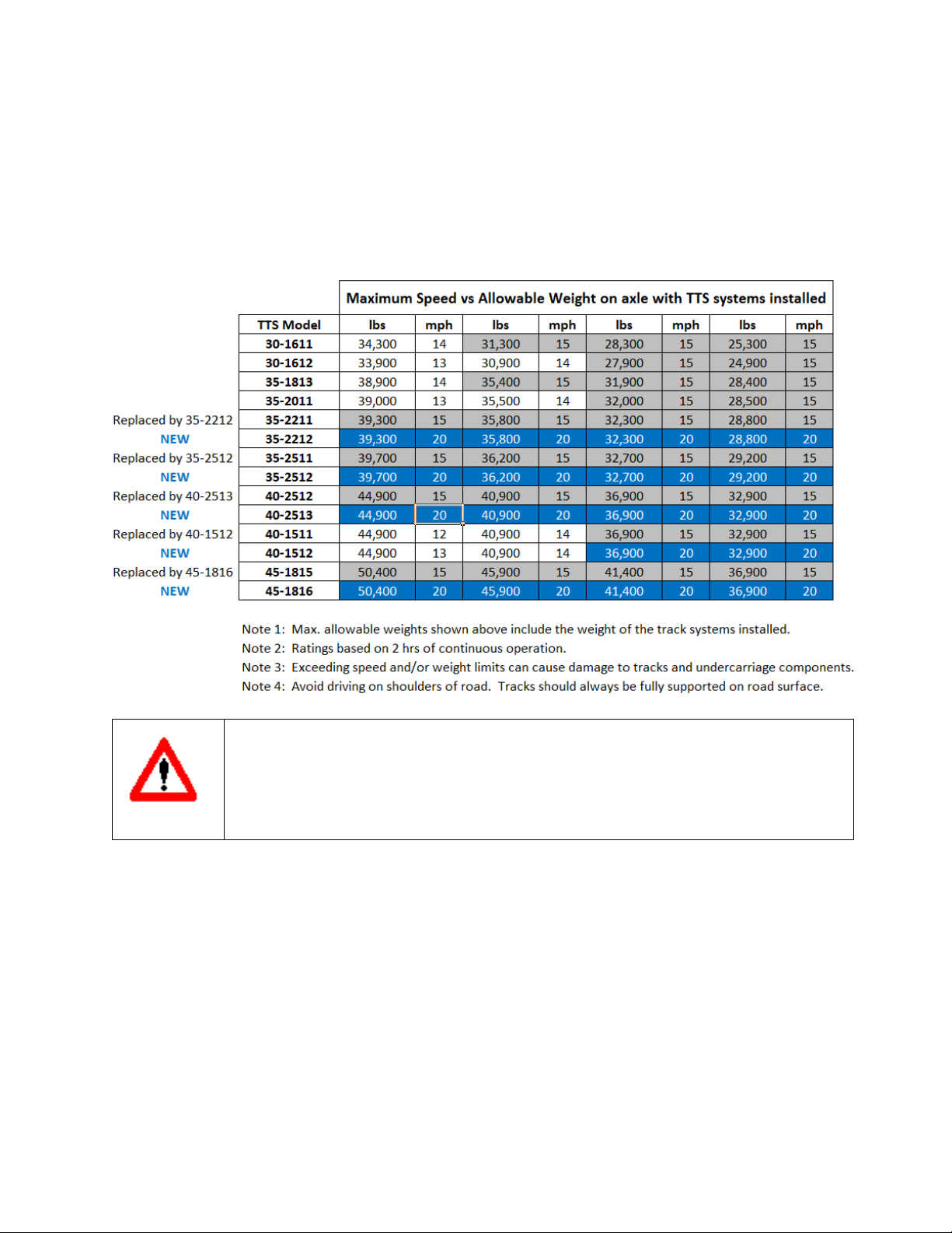
3.4 Weight Limitations ............................................................................................................... 9
3.5 Transport Limitations......................................................................................................... 10
3.6 Minimum Turning Radius Limitations................................................................................. 10
3.7 Operational Guidelines...................................................................................................... 11
3.8 Track Break-in Procedures................................................................................................ 12
4.0 TRACK SYSTEM INSTALLATION ........................................................................................ 12
4.1 Handling of the Track System ........................................................................................... 12
4.2 Track System Installation .................................................................................................. 13
5.0 SCHEDULED MAINTENANCE ............................................................................................. 17
5.1 General information........................................................................................................... 17
5.2 Lubricant Table ................................................................................................................. 17
5.3 Maintenance Schedule...................................................................................................... 18
5.3.1 Daily maintenance or every 10 working hours............................................................. 18
5.3.2 Weekly maintenance or every 50 working hours ......................................................... 19
5.3.3 Monthly maintenance or every 100 working hours ...................................................... 21
5.3.4 Every 5 years or 2000 working hours .......................................................................... 21
5.4 Off Season Storage........................................................................................................... 21
6.0 ROUTINE MAINTENANCE ................................................................................................... 22
6.1 Check Track Alignment ..................................................................................................... 22
6.2 Track Alignment Procedure ............................................................................................... 22
6.3 Track system inspection .................................................................................................... 24
6.4 Adjusting track tension ...................................................................................................... 24
6.5 Track Removal .................................................................................................................. 25
6.6 Track Installation ............................................................................................................... 25
7.0 TROUBLESHOOTING .......................................................................................................... 26
8.0 ADDITIONAL INFORMATION............................................................................................... 26
9.0 WARRANTY CERTIFICATE ................................................................................................. 27

CPB-516 Operation and Maintenance Manual – TTS 30-40-45 Series (excluding 45-1814) (01-2020)4
1.0 FOREWARD
This manual provides important operation and maintenance instructions to maximize the
benefits of the Camso Trailed Track System (TTS) and to ensure performance in the field
for many years to come.
1.1 Literature Information
This manual was prepared with the latest information available at the time of publication.
Read this manual carefully before operating or servicing the undercarriage(s).
The photos, illustrations, and data used in this manual were current at the time of printing,
but due to possible production changes, your undercarriage may vary slightly. Camso
reserves the right make changes to new production undercarriages as necessary without
notification. This document must be considered as an integral part of the rubber track
system, it must always be available for reference near the machine, even in the case of
sale, and until end of life. Should the operations and maintenance manual supplied with
the track system be damaged or missing, please see your dealer to request another copy
and/or contact Camso immediately.
1.2 Maintenance Intervals
Use the pulling machine hour meter to determine servicing intervals. Calendar intervals
are also shown and can be used instead of hour intervals. Recommended service should
always occur on the interval that occurs first. Under extremely dusty or wet operating
conditions more frequent lubrication may be needed. Perform service on items at
multiples of the original requirement. For example, at every annual or 250 hour service
interval, also service items listed under monthly or 100 hours, weekly or 50 hours, and
daily or 10 hours.
1.3 Camso Product Identification Number
The track system PIN plates will display the model and manufacturing date and sequence
number on both LH and RH undercarriage system. Each undercarriage has a unique
serial #.
If a serialized axle is also provided by Camso, it will also have a plate installed in the
center of the axle. Track part # and serial # are embossed into the edge of the track
carcass for ease of identification.
Undercarriage
Serial #
Model #
Track
Part #
Serial #
(on edge of track carcass)

CPB-516 Operation and Maintenance Manual – TTS 30-40-45 Series (excluding 45-1814) (01-2020)5
2.0 SAFETY
2.1 Important Safety Information
Read and understand this manual, the operation manual for the equipment the
undercarriage is mounted to, and the manual for all attachments before operating,
servicing or repairing an undercarriage.
Most personal injuries occurring during equipment operation, maintenance, or repair are
caused by failure to observe basic safety rules and precautions. In most cases, an injury
can be avoided by recognizing hazardous situations before an injury occurs.
A person must be alert to potential hazards. This person should also have the necessary
training, skills and tools to perform these functions properly.
Improper operation and maintenance of this product can be hazardous and may result in
injury or death.
Do not perform any lubrication, maintenance or repair on this product, until you have read
and understood this Operators manual.
Safety precautions and warnings are provided in this manual. If these hazard warnings
are not heeded, bodily injury or death could occur to you or to other persons.
Not every possible circumstance that might involve a potential hazard can be anticipated.
The warnings in this publication are not all inclusive. If a tool, procedure, work method or
operating technique not specifically recommended by Camso is used, you must satisfy
yourself that it is safe for you and others.
You must also ensure the product is not damaged or made unsafe by the operation,
lubrication, maintenance or repair procedures that you choose. The information,
specifications, and illustrations in this publication are based on information that was
available at time of printing.
3.0 GENERAL INFORMATION
3.1 Technical Description
Camso Trailed Track Systems allow machines to move on muddy and soft soils which
have limited carrying capacity. The wide supporting surface of the track system also
reduces soil compaction.
Camso track systems are mounted on an axle frame. Certain equipment requires a
special axle to be installed prior to track system installation. Please contact your dealer
for more information.
Camso track systems are designed to maximize the performance and productivity of your
pull-behind applications with:
• Even weight distribution to easily and safely handle uneven terrain
• Excellent flotation to minimize soil disturbance (40 - 70% ground pressure reduction vs. tires)
• Maximum reliability to assure you get the job done when tires are not able to do so

CPB-516 Operation and Maintenance Manual – TTS 30-40-45 Series (excluding 45-1814) (01-2020)6
TTS uses Camso rubber tracks, specifically designed for pull-behind applications to
provide:
• Reduced vibration during transport
• Lower turning resistance
• Minimal soil disturbance
• Long life
The patented undercarriage design incorporates independent movement of the midrollers
both front-rear and side-side delivering:
• Even weight distribution, allowing tracks to follow ground contours
• A smooth ride over rough terrain
• Reduced point loads increasing longevity of the undercarriage and implement
components
Besides the above listed characteristics, Camso rubber track systems introduce other
advantages:
•Reduced power requirements on soft soils
•Minimal possibility of rubber track de-tracking from the undercarriage
•Adequate roading speed
•Limited soil damage, even during end of field maneuvers
•Reduced risk of self-sinking in the mud in case of slipping
3.2 Track System Components
Idler Wheel
Doghouse assy(s)
Mid-roller wheel

CPB-516 Operation and Maintenance Manual – TTS 30-40-45 Series (excluding 45-1814) (01-2020)7
Midroller Oscillation Cavity, 125 ml of
universal trandraulic fluid (1 per
undercarriage). Plug torque is 25 ft-lb
(34Nm)
Front and rear Idler hubs,
500 ml of universal
trandraulic fluid (4 Hubs
per undercarriage). Plug
torque is 25 ft-lb (34Nm)
Midroller hubs, 215 ml of
universal trandraulic fluid (2
Hubs per undercarriage).
Plug torque is 25 ft-lb (34Nm)
Detensioning bolt
and jam nut
Track tension spring
Midroller Oscillation Cavity, 125
ml of universal trandraulic fluid (3
per undercarriage). Plug torque is
25 ft-lb (34Nm)
Idler and Mixdroller Hub, 180 ml of
universal trandraulic fluid (10 hubs per
undercarriage). Plug torque is 25 ft-lb
(34Nm)
Alignment Bolt 221 ft-lb (300
Nm) & Lock Plate Bolt 96 ft-
lb (130 Nm). (2 per
undercarriage, 1 each side)

CPB-516 Operation and Maintenance Manual – TTS 30-40-45 Series (excluding 45-1814) (01-2020)8
Frame
The main frame consists of a weldment or casting which hangs the front alignment
assembly and rear tension link. The front alignment yoke and rear tension link are cast
members, allowing for close tolerance machining and structural rigidity.
Axles
Front and rear axles are machined from the yoke castings, allowing for dimensional
stability and few moving parts. They feature oil bath hubs mounted on tapered bearings
and mechanical seals for extreme working conditions. Each hub has its own oil reservoir
with access port for maintenance and checking oil levels.
Idlers and Midrollers
The idlers have the function of guiding the rubber track by acting on the lateral surfaces of
the guide lugs. The midrollers distribute the majority of the machine weight to the ground.
They are mounted on pivoting arms connected to the frame reducing vibration and shock
loads.
Tensioning system
The tensioning system is located between the 2 rear idlers. The tension force is provided
by a mechanical spring mechanism. Track tension is provided by the spring and does not
need adjustment during operation and changing field conditions. Provisions are made to
compress the spring allowing for removal of idlers and track assemblies during
maintenance and servicing.
Rubber track
The rubber tracks are manufactured with high quality rubber and high strength steel
cabling inside for superior durability and reliability. The tread layout ensures good
flotation, excellent life, and self-cleaning characteristics.

CPB-516 Operation and Maintenance Manual – TTS 30-40-45 Series (excluding 45-1814) (01-2020)9
3.3 Specifications and Dimensions
TTS
Models
Track
Width
Overall
Height
Overall
Length
Ground
Contact -
Per Pair
Bogie
Axles
Per
UC
Capacity -
Per Pair
(in)
(in)
(in)
(in2)
(lbs)
30 Series
30-1611
16.5
31.0
83.1
1719
1
30,000
30-1612
16.5
30.5
72.7
1383
1
30,000
35-1813
18.0
30.5
72.7
1508
1
35,000
35-2011
20.0
30.5
72.7
1676
1
35,000
35-2211 &
35-2212
22.0
30.5
72.7
1844
1
35,000
35-2511 &
35-2512
25.0
30.5
72.7
2095
1
35,000
40 Series
40-1511 &
40-1512
15.0 40.4 104.4 1086 3 40,000
40-2512 &
40-2513
25.0 31.0 83.1 2605 1 40,000
45-1815 &
45-1816
18.0
40.4
104.4
1303
3
45,000
3.4 Weight Limitations
Camso track systems are limited to operating weights as listed in the table below. Do not
exceed these weight limitations or track system damage or component failure may result.
Series
Total Scale Weight Capacity per Set (2 undercarriages)
Kg
Lbs
30
13,600
30,000
35
15,880
35,000
40
18,150
40,000
45
20,411
45,000

CPB-516 Operation and Maintenance Manual – TTS 30-40-45 Series (excluding 45-1814) (01-2020)10
3.5 Transport Limitations
Camso track systems are designed for field use and field operational speeds. High speed
transport, especially with loaded implements is not recommended and may result in track
damage due to heat. If extended transport is required between operating locations, the
following speed and duration limits should be observed:
WARNING
Exceeding speed limitations may result in equipment and property
damage, injury, death and void warranty coverage.
If additional distances are required, a 30 minute cool down period is recommended before
transport is resumed. Absolute speed and duration levels may vary depending on system
type and ambient conditions. Limiting weight and speed will help avoid track heat buildup
that could cause reductions in track life.
3.6 Minimum Turning Radius Limitations
Camso track systems operate best when running straight or in gentle turns. If a track
system is pivot or spot turned, the opportunity exists for soil and dirt to be ingested into
the system. Even though TTS has a tension recoil system, if that tension recoil is

CPB-516 Operation and Maintenance Manual – TTS 30-40-45 Series (excluding 45-1814) (01-2020)11
exceeded, high loads in the frame and track can be generated which may cause track or
system damage, Camso recommends that minimum turning radius limits be strictly
observed, both in the field, and also on hard ground or pavement, to avoid high stresses
due to debris ingestion, potential untracking situations, high twisting and side loads, and
significant ground scrubbing of the track treads, especially if such a turn is attempted with
fully loaded or folded systems.
Operating
Condition
Minimum Turning Radius
Field or Road
1.5 x the overall length of the tractor + implement
3.7 Operational Guidelines
•Any application differing from the ones prescribed in this manual are to be considered
improper and potentially dangerous.
•Correct track tension is required for best performance and track life.
•Camso TTS can work in extreme conditions: for operator and machine safety, be sure
to know your surroundings.
•Camso TTS is free to pivot around the main axle following ground contours. During
transition over uneven ground terrain, check for interferences and move slowly to
avoid over-oscillating the undercarriage.
•Overall width and height of machine/equipment with Camso TTS could differ from the
original width and height with tires. Be sure to know actual machine height and width
as well as width restrictions prior to operation.
•Cross large ground irregularities with suitable speed reduction and/or proper incidence
angle. In particular, when high, sharp bumps are crossed move forward slowly to avoid
shocks on the machine.
•Camso TTS does not damage standard road-bed constructions. Operators must know
and respect road traffic laws.
•Rubber tracks have not been designed for extended use on the road. Camso is not
responsible for track and system damage resulting for extended road use. Long road
periods and/or roading at higher than recommended maximum speeds may cause
premature wear or failure of the track or wheels and is not a warrantable condition. To
reduce damage during roading decrease overall machine weight and decrease machine
speed, see “Transport Limitations” section for further information.
•Long runs on side slopes increase the wear on the side of guide lugs and idlers.
•Keep material out of the undercarriage. Inspect undercarriage daily, removing any
material as necessary. In some conditions inspect more frequently.

CPB-516 Operation and Maintenance Manual – TTS 30-40-45 Series (excluding 45-1814) (01-2020)12
•If a machine becomes stuck, clear away as much material from the undercarriage as
possible prior to pulling the machine out.
•Avoid short turning radius turns and operation(s) especially when loaded. Spot turning
creates debris ingestion and can also induce high torque loading in the system.
•Configure drawbar and hitch correctly during field operation(s).
•Use caution when operating track systems in loose, flowing material. Loose material
can become trapped between track and idlers, resulting in track damage.
•Keep material out of the undercarriage. This may require scraping material out of tight
places and in some conditions require frequent inspection and cleaning.
3.8 Track Break-in Procedures
Guide lug wear is reduced when correct break-in procedures are followed. During the
break-in period, rolling components undergo a polishing-in process to achieve a smooth
steel to rubber interface with the guide lug. Rubber uses dust and dirt as a dry lubricant
during break-in and operation to minimize heat and reduce rubber stickiness. New tracks
should be exposed to dry and dusty soil conditions as soon as possible. Operation
without dust or soil in the system, especially during high speed roading, generates
high levels of damaging heat. If roading must be done, a dry lubricant such as soil, talc,
graphite, oil dry or cat litter should be applied to the guide lugs periodically during roading
until field operation resumes.
ATTENTION:
NEW SYSTEMS REQUIRING EXTENDED TRANSPORT SHOULD BE
CARRIED ON A FLAT BED. DO NOT ROAD A NEW SYSTEM WITHOUT
FIRST CHECKING ALIGNMENT AND INTRODUCING THE TRACKS TO
DIRT OR DRY LUBRICANT OR GUIDE LUG DAMAGE MAY RESULT
4.0 TRACK SYSTEM INSTALLATION
The track system is mounted on an axle frame. Certain equipment requires a special axle
to be installed prior to track system installation. Contact your dealer for more information
and to determine if the track system can be installed on your implement.
4.1 Handling of the Track System
The track systems can be handled by fork lifts lifting the machine from the base or by
hoists using textile bands.

CPB-516 Operation and Maintenance Manual – TTS 30-40-45 Series (excluding 45-1814) (01-2020)13
WARNING
Danger of crushing. Use suitable lifting devices (capacity at least 9000 lbs
(4100Kg)), wear safety equipment and observe the safety rules.
If using a fork lift use for handling operations, be careful not to damage the
rubber track. Metal chains or cables are not recommended
4.2 Track System Installation
1. Clean the implement thoroughly before proceeding with the installation. Removal
of dirt and debris makes access to the frame and attaching fasteners easier.
2. Move the implement to a hard, level surface to ensure a stable work area to
support the implement during the track system installation.
IMPORTANT: Locate the identification tags, as shown above, on both undercarriages,
and record the model number and serial numbers on the warranty certificate for your
records.
3. Raise and support implement such that the rear tires are just off the ground.
Serial number identification plate, unique serial # per undercarriage.

CPB-516 Operation and Maintenance Manual – TTS 30-40-45 Series (excluding 45-1814) (01-2020)14
IMPORTANT
Safety of the installation depends on the right operation in lifting
and supporting the machine. Check the work area thoroughly and
work in a level area. Respect safe operating practices, operate in
conditions of enough light. Make sure the free spaces of the work
area are suitable for the dimensions of the parts to be handled and
for the lifting equipment maneuvers. Be careful: risk of injury.
4. Remove the tire and rim assemblies.
5. Remove the axle and hub assemblies from the implement frame (as required).
6. Install track fitment axle. Tighten mounting hardware and review fitting locations
for proper torque requirements as required.
WARNING
Danger of crushing. Use suitable lifting devices (capacity at least
9000 lbs (4100Kg)), wear safety equipment and observe the safety
rules.
In case of fork lift use for handling operations, be careful not to
damage the rubber track. Metal chains or cables are not
recommended.
IMPORTANT
Should a motorized lifting device be used, assistance on ground
during operation of handling, coupling and assembly is needed.
Do not stand between lifting device and axle assembly when
mounting axles to implement. Be careful: risk of injury.

CPB-516 Operation and Maintenance Manual – TTS 30-40-45 Series (excluding 45-1814) (01-2020)15
7. Lightly grease machined surface of center pivot pin and insert into the receiver end
of the axle. Rotate the pin to align the rear mounting hole in the receiver pin.
Install the bolt and locknut provided with the kit. Torque pin bolt and lock nut to
130 Nm (96 ft-lbs) .
8. Install the inner thrust washer against the axle pin flange.
9. Apply a light amount of grease to the center pivot pin.
10. Slide the undercarriage onto the axle pin. NOTE: Care must be exercised to avoid
damage to lip seals on the center bore of the undercarriage during installation.
Using a fork truck, lift the undercarriage assembly onto the center pivot pin.
WARNING
Make sure undercarriage is installed with track tensioner assembly
(spring) positioned to the rear of implement. DO NOT install the
track system with the tensioner positioned to the front of the
implement.
11. Install outer thrust washer, retaining cap and retainer cap bolts & washers. Torque
retainer bolts to 320 Nm (236 ft-lbs)
12. Repeat steps 7 through 11 for the other of the axle mounting pin assembly.
13. Remove jack stands and/or supports and lower implement to the ground.
Grease these
areas

CPB-516 Operation and Maintenance Manual – TTS 30-40-45 Series (excluding 45-1814) (01-2020)16
14. Check and re-torque all wheel lug bolts as follows:
Wheel bolt diameter
Torque (Nm)
Torque (ft-lbs)
M16 (Midrollers)
320
236
M20 (Idlers)
620
457

CPB-516 Operation and Maintenance Manual – TTS 30-40-45 Series (excluding 45-1814) (01-2020)17
5.0 SCHEDULED MAINTENANCE
5.1 General information
Three factors: proper use, regular inspections, and maintenance are essential to ensure proper
performance and reliability of your Camso trailed track system.
It is strongly suggested to respect the recommended maintenance and inspection schedule in this
section for best track system life, proper performance, and reduced downtime.
Before any operation, clean all debris and material from the track system and make a general
analysis of the machine condition. Pay attention to wear components such as the track and inner
flanges of the wheels. Identifying and resolving issues early reduces downtime and operating
costs.
IMPORTANT
Routine and extra maintenance must be performed by qualified and
authorized personnel.
Before starting any kind of operation on the machine, disconnect the
transmission, stop the engine, set on the emergency brake, remove the
key and allow machine to stop completely and cool.
Make sure that mobile parts with safe fixed positioning are locked and
the tools used for maintenance are suitable for the type of service
Camso is not responsible for direct or indirect damages occurred to
people or things due to tampering, removal or modification of the safety
devices, or caused by modifications of the machine without any previous
authorization.
5.2 Lubricant Table
Use and description
Location
Viscosity grade
Grease for heavy
mechanical components
Carrier bearings and frame
pivot pin joints NLGI GC-LB
Oil Bath Reservoirs Idlers and Midroller Hubs
and Midroller axle pivots
Northland Universal
Trandraulic Oil (or equivalent)

CPB-516 Operation and Maintenance Manual – TTS 30-40-45 Series (excluding 45-1814) (01-2020)18
5.3 Maintenance Schedule
Task
Daily
or 10h
Weekly
or 50h
Monthly
or 100h
Annual
or 500hr
5 years or
2000hr
Inspect and clean track system
X
Inspect track condition
X
Check track alignment
X
Inspect for oil leaks on idler,
midroller hubs and pivot axles X
Grease undercarriage and track
system pivot points
X
Check track tension X
Re-torque wheels
X
Repack carrier roller hub
bearing(s) (if equipped)
X
Replace hub and pivot oil and set
wheel bearing rolling torque
X
5.3.1 Daily maintenance or every 10 working hours
1. Clean and remove debris from track system. Material build-up on track system
components can lead to excessive wear and premature failure.
2. Track system inspection. Walk around the machine inspecting each track system
and axle assembly. Identifying and resolving issues early is key to improving track
system life and decreasing operating expenses. See “Track System Inspection” in
the Routine maintenance section for more information.
3. Check rubber track alignment daily by inspecting the guide lugs. If excessive wear
or chunking of the guide lug is occurring, track alignment may need to be adjusted.
For additional information, refer to the “Track Alignment Procedure” section.
4. Inspect idler, midroller and midroller pivot axles for leaks. If any are noted, check
oil level of the hub to be sure oil is up to the fill hole when on a level surface.

CPB-516 Operation and Maintenance Manual – TTS 30-40-45 Series (excluding 45-1814) (01-2020)19
5.3.2 Weekly maintenance or every 50 working hours
1. Grease undercarriage and track system pivot points.
1.
Main center pin (2 shots of grease)
2.
Main frame pin (2 shots of grease)
3.
Tension link pin (2 shots of grease)

CPB-516 Operation and Maintenance Manual – TTS 30-40-45 Series (excluding 45-1814) (01-2020)20
1.
Main center pivot pin (4 shots of grease-
grease fitting in end of center pivot pin)
2.
Main frame pin/rear (2 shots of grease)
3.
Tension link pivot pin (2
shots of grease)
4.
Doghouse pivot (2 shots of grease)
5.
Alignment arm pivot pin (2 shots of grease)
2.
4.
5.
1.
3.
This manual suits for next models
17
Table of contents
Other CAMSO Tractor Accessories manuals
Popular Tractor Accessories manuals by other brands

Howard
Howard HK32 HY Operating instructions & parts list

McConnel
McConnel PA50 Mk3 Operator's manual

matev
matev FPS-FKH-NH Boomer 35 MJ 2021 operating manual

McConnel
McConnel ROBO-FLAILHEAD 1300 Operator's manual

Nordic Plow
Nordic Plow ZERO TURN 49 MOUNTING KIT manual

Avantco
Avantco A36279 Operator's manual for Attachment