HM Electronics HM3000CDM User manual

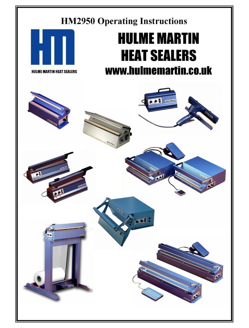
HM3000CDM Operating Instructions
HULME MARTIN HEAT SEALERS
HULME MARTIN
HEAT SEALERS
www.hulmemartin.co.uk


SAFETY INSTRUCTIONS – HEAT SEALING EQUIPMENT
A. Protection against hazards arising from the electrical equipment
1. Safety warnings and instructions in the operators instruction sheets and
attached to the machine should be followed with care.
2. The equipment has an earthed power cable with integral 5 amp plug to
BS 1363/A fitted with a 5 amp fuse. The panel mounted fuse holder on
the machine is fitted with a 3.15A antisurge fuse for additional
protection. If either fuse fails the reason should be investigated and the
machine inspected and tested to ensure that there are no causative
faults. Higher value fuses must not be used, as they do not provide the
required level of protection.
3. Ensure that the power is switched off and the cable plug is removed
from the supply outlet before any servicing is undertaken on the
product.
4. Increased user safety can be achieved if a residual current device
(RCD) is used in the supply circuit to the heat sealer. This applies
particularly in damp conditions but the equipment must not be allowed
to get wet, either from sealing liquids, cleaning or inclement weather.
Only specially designed water resistant sealers should be used in
these circumstances. Electrical components and internal wiring, unlike
the element assembly, are not all protected by the low voltage safety
transformer, which powers the element.
5. Switch off the power supply when the machine is not attended.
6. The equipment should be regularly serviced and subjected to Portable
Appliance Test procedures in accordance with the Health and Safety
Electricity At Work regulations 1989.
7. It is essential that only approved spares be used for servicing this
equipment. Incorrect element wire can result in excessive electrical
load on internal components, which can lead, to malfunction and
failure.
Note
Hulme Martin Heat Sealing equipment satisfies the Health and Safety
requirements of the Electrical Equipment (Safety) Regulations 1994, CE Low
Voltage Directive 2006/95/EC

B. Protection against non electrical hazards
1. The equipment is designed to be operated on a flat, level surface to
ensure machine stability. In the case of chain operated machines, the
equipment should be securely screwed or clamped to the workbench
using the flanges provided, to avoid dislodging the machine when the
pedal is depressed.
2. Heat sealing machines must not be used for packing flammable or
explosive materials unless specifically modified to do so.
3. When sealing PVC and some other plastic films, which may produce
potentially harmful fumes, adequate airflow ventilation or extraction
may be required.
4. The heating element and jaws can become hot during sealing and
adequate cooling time must be allowed before touching these parts of
the machine.
5. Care should be taken on machines fitted with cutting knives that the
blade is moved to a safe position before attempting to reach between
the jaws. On hand operated machines, which are pivoted at one end of
the pressure bar the knife will slide towards the pivot point when the
pressure bar is lifted. For safety ensure that the blade is positioned at
the pivot end before lifting the pressure bar.
6. The heating cycle on impulse sealers is controlled by a timer allowing a
maximum heating time of 4 seconds. If the timer indicator light does
not go out at the selected time and heating continues, switch off the
power immediately and investigate the fault after removal or
disconnection of the element.
7. Repeated operation of the machine without sufficient cooling time
between cycles can cause accumulative heat build up in the element
resulting in poor seals, damaged elements and excessive temperatures
8. Ensure that hands and fingers are clear of the pressure bar before
actuating the foot pedal. The element will not operate until the
pressure bar is fully closed but some discomfort will result from the
pressure applied manually or by solenoid operated units.

IMPULSE SEALING EQUIPMENT
To ensure that satisfactory sealing performance is achieved and that
service life of consumable spares (such as element wire, Teflon and
rubber pressure pads) are maximised, it is necessary to understand the
operating principles of this type of equipment.
1. To adjust the heat setting for a particular thickness of material, the
power output is not varied, and varying the length of time that the
current passed through the element resistance wire effects adjustment.
The timer control allows infinitely variable time adjustment up to a
maximum of around 4 seconds.
2. When the red heating indicator light goes out the temperature has
reached its maximum and the polythene is molten to effect the weld. It
is important that before allowing the jaws to open for removal of the
polythene a short cooling time is allowed to enable the polythene to
solidify and to regain its original strength. On machines fitted with a
dual timer control, the cooling time can be pre set but on standard
machines with simple heating time control, the operator should allow
sufficient time for cooling before releasing the jaws. Depending on
material thickness a cooling time of 1 to 7 seconds is usually sufficient.
3. To complete the seal in the minimum possible time considerable power
is applied to the element for the short duration of the welding cycle.
The instantaneous temperature reached during the brief cycle is very
high, but close contact of the rubber pressure pad removes excess
temperature and prevents deterioration of the thin Teflon barrier tape.
4. It follows that if the pressure bar is released before the temperature
reduces to a level that the Teflon can withstand, it will deteriorate
rapidly and require premature replacement.
5. For this reason adequate cooling allowance is critical to the service life
of the Teflon. Although capable of withstanding up to 20,000 seals
before replacement, insufficient cooling time can cause burning within a
very short period.

6. If the Teflon is not replaced when showing signs of wear, the polythene
will stick and seal quality will deteriorate. Also the rubber pressure pad
will start to wear and if this is allowed to continue to the stage where
the surface of the pad is burnt and uneven, the resulting ‘air gap’
between the pad and element will reduce heat transfer and cause
further rapid deterioration of the Teflon. Excessive burning will
eventually result also in the element wire requiring replacement.
7. To avoid this ‘ vicious circle’ always operate the machine at the
minimum heat setting consistent with satisfactory seal quality. Allow
sufficient cooling time between each successive seal. When sealing
repetitively at high frequency reduce the heating time from its original
setting to compensate for residual heat build up in the element.
8. The micro switch is set to avoid application of power to the element
until the rubber pad is fully aligned and pressed closely to the Teflon to
allow the necessary heat transfer. The rubber pressure pad is
sufficiently pliable to accommodate several thickness’ of polythene, but
accidental closure onto thicker objects or attempting to seal bubble
pack material and heavy paper laminate gusseted materials will cause
deterioration of the Teflon for the reasons explained previously.
9. The rubber pressure pad, and element wire strip are easily replaceable,
but care in operating and maintenance of the Teflon barrier tape can
extend the service interval before element reconditioning becomes
necessary.
10. If the machine fails to seal, but the on off switch and indicator lights
show that the power and timer circuits are operating correctly, unplug
the element and check the condition of the resistance wire and Teflon.
Simple replacement of these low cost consumable spares will normally
restore the full performance of the equipment.

HM3000CDM POLYTHENE HEAT SEALER
OPERATING INSTRUCTIONS
General
Before connecting the machine to the electricity supply, check the operating
voltage on the name plate attached to the base of the machine.
The wires in the mains lead are coloured in accordance with the following
code:
Green & Yellow Earth
Blue Neutral
Brown Live
Ensure that the machine is correctly earthed and connected to the mains
supply with a 5 amp fused plug.
The heating element operates at a reduced safety voltage and the machine
has its own 3.15 amp internal fuse, accessible at the rear of the body.
Installati n
For transportation purposes the black handle has been fitted to the upper arm
in the reverse position. Before operating the machine this handle should be
fitted to the correct position.
Operating Instructi ns
Switch on the machine using the amber on/off switch on the side of the
machine. Check that the switch lights up to indicate that the machine is
powered.
The HM3000CDM impulse sealer is fitted with a dual electronic timer
controlling the heating and cooling cycles. When sufficient pressure is applied
to the pressure bar, the audible ‘click’ of the microswitch and the illumination
of the red LED indicator lights will confirm that the machine is correctly
adjusted and that power is being applied to heat up the element.
The heating time is variable between 0 and 3.5 seconds using the external
control knob. The cooling cycle is also adjustable to allow a sufficient cooling
time before the pressure bar is released.

Once the pressure bar has been depressed, the magnet will hold the bar
down until both neon lights go out. This should prevent the possibility of
insufficient cooling which can result in premature wear of the teflon barrier
tape and other consumable spares.
To extend the service life of the consumable items, always operate at the
minimum setting consistent with good seals and allow adequate cooling time
before removal of the bag.
Setting the Heating Time
Switch on the machine and set the timer control to position No. 2. Place the
polythene bag between the jaws and depress the upper jaw to the preset stop
point. The timer light will illuminate for a period of approximately one second.
Allow a further two seconds to cool before releasing the pressure from the
sealed bag. Examine the seal and progressively increase the heating and
cooling time until satisfactory seal strength is achieved.
Maintenance
The complete element assembly can be unplugged (without tools) from the
machine body so that it can be replaced with a new or reconditioned unit.
Removal of the Teflon barrier tape from the displaced element enables the
wire to be inspected and replaced if kinked or damaged. When rewiring the
element, ensure that the wire passes over the pins, down through the hole at
each end of the bar and up through the contact pin hole. Secure one end with
the nut and washer and tension the wire strip before tightening the remaining
nut. This ensures that any excess wire is on the top of the element. It is
important that this excess is removed to avoid any risk of a short circuit to the
metal body that can result in damage to the timer circuit.
To replace the pressure pad, fit approximately 30mm at each end of the
pressure bar and work the pad into the gap working towards the centre.

SPARES
The following consumable spares will enable the machine to be serviced as
required.
300211 Element Assembly complete each
300203 Teflon Barrier Tape pkt 5
300205 Rubber Pressure Pad each
300204 Underwire Insulating tape pkt 5
300206 Resistance wire strips pkt 5
490 Cutter blades pkt 10
445 Safety cutter Assembly each
When ordering spares please quote the serial number of the machine as
printed on the plate on the base of the machine. If special modifications such
as wide seal elements have been fitted to the machine ensure that the spares
department are informed when ordering these parts.

Spares Items F r 3000
Element Bar Assy 300211
Teflon Barrier Tape
300203
Element Wire Strip
300206
Insulation Tape 300204
Soft Rubber Pad 300205
Black Neoprene Pad
300265
Safety Cutter Assy
445
Cutter Blades 490

Using the 445 Safety cutter assembly
Safety Tab
For transportation and additional safety, the manual cutting device is fitted with a locking
‘safety tab’, which must be removed before the cutter can be used. To remove the safety tab
hold it firmly and pull it horizontally, with a small rocking motion, away from the blade carrier
marked ‘caution cutter’ the tab will simply pull out of its locked position, it is held via two
prongs. To lock the blade in a safe position simply replace the ‘safety tab by pushing the
prongs back in to the blade carrier.
Operation
Even with the ‘safety tab’ removed the blade is fully withdrawn and not exposed, ensuring the
operators safety at all times. As with any sharp objects extreme caution should always be
used.
To trim off the excess material above the seal or manufacture bags from layflat tubing simply
close the sealing jaws on your heat sealer. The LED indicators will illuminate, then fully press
the yellow blade carrier marked ‘caution cutter’ down level with the black carrier and slide the
cutter assembly along the pressure bar housing. The depth of the cut is pre set at the factory
and no adjustment should be necessary. If during the course of time the cutter needs
adjustment the slider bar (carrying the cutting assembly) can be adjusted via the hexagon
head screws on the outside of the pressure bar housing.
Changing the blade
Please read all of the following instructions before changing the cutter blade
Eventually it will be necessary to replace the cutting blade. Please always use extreme
cauti n when handling these blades, as even when they no longer cut the material they can
be extremely sharp.
Remove the aluminium cutter stop fitted on the machines pressure bar housing. This is
located at one end and secured with two M3 countersunk screws to stop the cutting assembly
coming out during use, as illustrated below.
Remove 2 x M3 counter sunk screws from the end of the pressure bar housing. Lift out the
aluminium cutter stop. Slide the cutter assembly to this exit point on the pressure bar housing
and lift out the assembly to remove.

Safety Tab
Activating spring part No. 446
Blade carrier marked
‘Caution cutter’
Black carrier handle
Retaining button
Cutter Blade part No.490
Safety Cutter Assembly part
No.44
CHANGING THE BLADE
Always use cauti n when changing the blade

Hulme Martin Heat Sealers Duty f Care
Directive 2002/95/EC on the restriction of the use of certain hazardous
substances in Electrical and Electronic Equipment(RoHS)
The RoHS Directive stands for "the restriction of the use of certain hazardous substances in electrical and electronic
equipment". This Directive bans the placing on the EU market of new electrical and electronic equipment containing
more than agreed levels of lead, cadmium, mercury, hexavalent chromium, polybrominated biphenyl (PBB) and
polybrominated diphenyl ether (PBDE) flame retardants.
All machines manufactured from 1
st
April 2006 comply with the above
directive.
Directive 2002/96/EC on Waste Electrical and Electronic Equipment (WEEE)
The WEEE Directive aims to reduce the quantity of waste from electrical and
electronic equipment and increase its re use, recovery and recycling.
From 1
st
March 2007 Hulme Martin machines are marked with the ‘crossed out wheeled bin
symbol’ to ensure they are dealt with separately from general waste. We can arrange to
collect machines that are no longer required and ensure they are either recycled or disposed
safely. We will record details of all collected and recycled machines.
WEEE REG N WEE/DB1381SS
Packaging Directive
Directive 2004/12/EC (94/62/EC). Whilst we are not required to register under this directive
we use minimal packaging to ensure your purchase reaches you in a first class condition.
Packaging used has been recycled wherever possible and can be reused or recycled by the
receiver.
EC Declaration of Conformity
Machinery Directive 2006/42/EC
The Low Voltage Directive 2006/95/EC
Electromagnetic compatibility directive 2004/108/EC.
Our machines comply with the above directives. All new machines are built to
a high standard and subjected to visual and electrical tests at several stages
during their manufacture. Once assembled we produce test seals to ensure
quality standards are met. Finally every machine is Portable Appliance Tested
to ensure electrical safety requirements are met.
ISO 9000 Quality Management
Hulme Martin Heat Sealers Ltd operates from documented quality management systems to ensure we meet our
customers’ requirements. We conform to the required directives as listed above, and our equipment meets CE
requirements. Customers are welcome to visit our factory to inspect our documentation and manuals.
ISO 14000 Environmental Management
Hulme Martin Heat Sealers ensures its activities causes minimal effects on the
environment. We continually monitor our practices to achieve the best possible
improvement on our environmental performance.

Warranty
In the unlikely event that it becomes necessary to return the machine for
repair or maintenance, please ensure that it is adequately packed to avoid
accidental damage and include your advice note detailing the date of
purchase and invoice reference number. Defects occurring from faulty
materials or manufacture will be repaired free of charge within the 12 month
warranty period provided that the machine has not been misused; is correctly
maintained, and has not been subject to unauthorised repair. Consumable
spares items such as the heating element assembly, resistance wire strips,
Teflon barrier tapes, rubber pressure pads and transportation costs are
excluded from the warranty.
HULME MARTIN HEAT SEALERS LTD
Unit 5B, C untry Business Centre,
White C ttage Farm,
Lucas Green R ad,
West End,
W king,
Surrey
GU24 9LZ
Teleph ne 01483 476767 Fax. 01483 486343
www.hulmemartin.c .uk
Table of contents
Other HM Electronics Food Saver manuals
