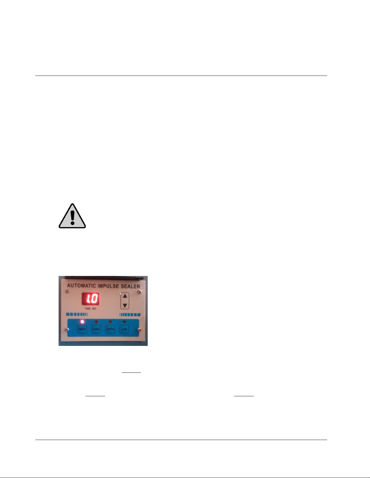
KS- F S I N S T R U C T I O N M A N U A L
1
Safety Instructions
WARNING!
Below are general safety precautions and warnings that should be
understood prior to setting up or operating your equipment. Read and fully understand all instructions and
warnings prior to using this unit. Your safety is most important! Failure to comply with procedures may
result in serious injury or property damage. Remember:
Your personal safety is your
responsibility.
Unsafe practices or unauthorized modifications could result in accidents or property damage. Failure to follow these
safety rules and take necessary precautions can result in serious injury as well as damage to equipment.
Never operate or service your sealer until you have read this manual completely and understand it fully.
Plug the sealer into a standard 120 Volt, 60Hz wall outlet or surge protector.
Do not use the sealer if the power cord, plug or any other parts are damaged. Be sure not to allow the
power cord to drape into your work area. Check that all parts are operating properly and perform the
intended functions. Check for any worn parts before starting operation. Check for all other conditions that
may affect the operation.
Reduce risk of unintentional starting. Make sure the power switch is in the "OFF" position before attaching
to the power source.
Always disconnect sealer from power source before servicing, changing accessories or cleaning the unit.
To provide protection against the risk of electrical shock, the power connection must be properly grounded
at all times.
Do not leave the sealer unattended when in use. Disconnect the sealer from the power source before
leaving the work area.
Sealer is used solely for sealing thermoplastic materials. Using the machine for any other purpose can cause
damage to the machine and operator. Do NOT use the machine for any other purpose other than to seal
thermoplastic materials. Doing so may result in damage to the machine and injury to the operator.
While operating machinery, wear close-fitting clothing and tie back long hair to prevent any external items
from getting caught in the machine. Do not wear jewelry when operating the sealer.
Never touch the heating elements with bare hand while the sealer is plugged into a power source, in
operation or just finished operation. Touching heated areas may cause fire and/or severe burns.