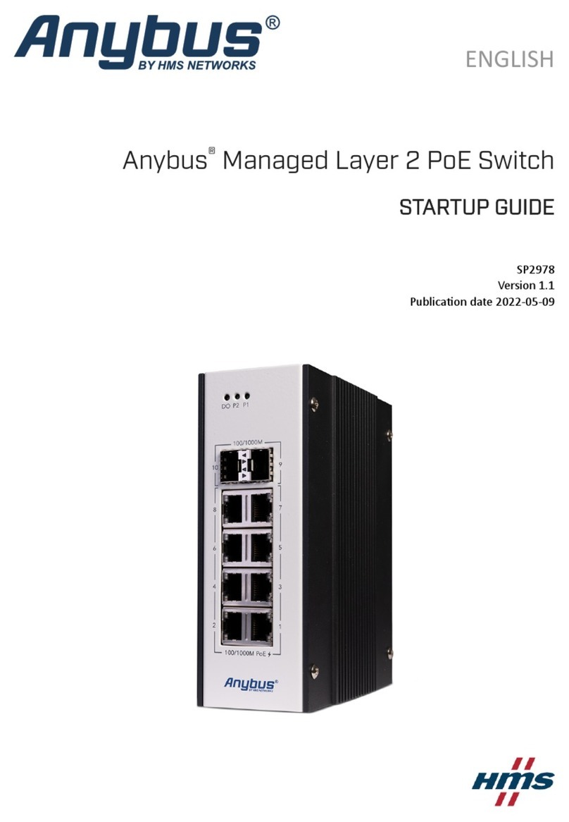
HMS Networks Anybus SP2555 User guide

Anybus®Unmanaged Industrial L2 Switch
STARTUP GUIDE
SP2555 1.1 en-US ENGLISH

Important User Information
Disclaimer
The information in this document is for informational purposes only. Please inform HMS Industrial
Networks of any inaccuracies or omissions found in this document. HMS Industrial Networks disclaims
any responsibility or liability for any errors that may appear in this document.
HMS Industrial Networks reserves the right to modify its products in line with its policy of continuous
product development. The information in this document shall therefore not be construed as a
commitment on the part of HMS Industrial Networks and is subject to change without notice. HMS
Industrial Networks makes no commitment to update or keep current the information in this document.
The data, examples and illustrations found in this document are included for illustrative purposes and are
only intended to help improve understanding of the functionality and handling of the product. In view of
the wide range of possible applications of the product, and because of the many variables and
requirements associated with any particular implementation, HMS Industrial Networks cannot assume
responsibility or liability for actual use based on the data, examples or illustrations included in this
document nor for any damages incurred during installation of the product. Those responsible for the use
of the product must acquire sufficient knowledge in order to ensure that the product is used correctly in
their specific application and that the application meets all performance and safety requirements
including any applicable laws, regulations, codes and standards. Further, HMS Industrial Networks will
under no circumstances assume liability or responsibility for any problems that may arise as a result from
the use of undocumented features or functional side effects found outside the documented scope of the
product. The effects caused by any direct or indirect use of such aspects of the product are undefined
and may include e.g. compatibility issues and stability issues.
Anybus®Unmanaged Industrial L2 Switch Startup Guide SP2555 1.1 en-US

Anybus®Unmanaged Industrial L2 Switch Startup Guide SP2555 1.1 en-US
Table of Contents Page
1 Preface ..................................................................... 3
1.1 About This Document . . . . . . . . . . . . . . . . . . . . . . . . . . . . . . . . . . . . . . . . . . . . . . . . . . 3
1.2 Document Conventions. . . . . . . . . . . . . . . . . . . . . . . . . . . . . . . . . . . . . . . . . . . . . . . . . 3
1.3 Trademarks. . . . . . . . . . . . . . . . . . . . . . . . . . . . . . . . . . . . . . . . . . . . . . . . . . . . . . . . . . . . 3
2 Safety ...................................................................... 4
2.1 Intended Use . . . . . . . . . . . . . . . . . . . . . . . . . . . . . . . . . . . . . . . . . . . . . . . . . . . . . . . . . . 4
2.2 General Safety . . . . . . . . . . . . . . . . . . . . . . . . . . . . . . . . . . . . . . . . . . . . . . . . . . . . . . . . . 4
3 Preparation ................................................................ 5
3.1 Package Checklist . . . . . . . . . . . . . . . . . . . . . . . . . . . . . . . . . . . . . . . . . . . . . . . . . . . . . . 5
3.2 Support and Resources . . . . . . . . . . . . . . . . . . . . . . . . . . . . . . . . . . . . . . . . . . . . . . . . . 5
4 Installation................................................................. 6
4.1 DIN Rail Mounting . . . . . . . . . . . . . . . . . . . . . . . . . . . . . . . . . . . . . . . . . . . . . . . . . . . . . 6
4.2 Connecting Ground and Power. . . . . . . . . . . . . . . . . . . . . . . . . . . . . . . . . . . . . . . . . . 7
4.3 Connecting to Ethernet. . . . . . . . . . . . . . . . . . . . . . . . . . . . . . . . . . . . . . . . . . . . . . . . 10
5 Verify Operation..........................................................11
5.1 Power LED Indicator. . . . . . . . . . . . . . . . . . . . . . . . . . . . . . . . . . . . . . . . . . . . . . . . . . . 11
5.2 Ethernet/IP LED Indicators . . . . . . . . . . . . . . . . . . . . . . . . . . . . . . . . . . . . . . . . . . . . . 12
6 Technical Data ............................................................13
6.1 Technical Specifications . . . . . . . . . . . . . . . . . . . . . . . . . . . . . . . . . . . . . . . . . . . . . . . 13

This page intentionally left blank

Preface 3 (14)
1 Preface
1.1 About This Document
This manual describes the installation of
Anybus Unmanaged Industrial L2 Switch.
For additional documentation and software downloads, FAQs, troubleshooting
guides and technical support, please visit www.anybus.com/support.
1.2 Document Conventions
The following conventions are used to indicate safety information and other
important content in this document:
WARNING
Instruction that must be followed to avoid a risk of death or serious injury.
Caution
Instruction that must be followed to avoid a risk of personal injury.
Instruction that must be followed to avoid a risk of reduced functionality
and/or damage to the equipment, or to avoid a network security risk.
Additional information which may facilitate installation and/or operation.
1.3 Trademarks
Anybus®is a registered trademark of HMS Industrial Networks. All other
trademarks mentioned in this document are the property of their respective
holders.
Anybus®Unmanaged Industrial L2 Switch Startup Guide SP2555 1.1 en-US

Safety 4 (14)
2 Safety
2.1 Intended Use
The intended use of this equipment is as a communication interface and
gateway. The equipment receives and transmits data on various physical levels
and connection types.
If this equipment is used in a manner not specified by the manufacturer, the
protection provided by the equipment may be impaired.
2.2 General Safety
Caution
Ensure that the power supply is turned off before connecting it to the
switch.
Connecting power with reverse polarity or using the wrong type of power
supply may damage the equipment. Make sure that the power supply is
connected correctly and of the recommended type.
Anybus®Unmanaged Industrial L2 Switch Startup Guide SP2555 1.1 en-US

Preparation 5 (14)
3 Preparation
3.1 Package Checklist
Item Pieces
Anybus Unmanaged Industrial L2 Switch 1
4 pin terminal block 1
Startup Guide 1
Safety and Regulatory Compliance Sheet 1
3.2 Support and Resources
For additional documentation and software downloads, FAQs, troubleshooting
guides and technical support, please visit www.anybus.com/support.
Have the product article number available, to search for the specific product
page. You find the product article number on the product cover.
Anybus®Unmanaged Industrial L2 Switch Startup Guide SP2555 1.1 en-US

Installation 6 (14)
4 Installation
4.1 DIN Rail Mounting
Mount the switch on a DIN rail in accordance with the EN 50022 standard.
Procedure
Mount the switch on a DIN rail:
1. Insert the upper end of the DIN rail clip into the DIN rail.
2. Push the bottom of the DIN rail clip into the DIN rail.
Anybus®Unmanaged Industrial L2 Switch Startup Guide SP2555 1.1 en-US

Installation 7 (14)
4.2 Connecting Ground and Power
Terminal Block
Contact
Number
Description
1 Power Input V+
2 Power Input V–
3 Power Input V+
4Ground (GND)
4.2.1 Installing Terminal Block
Procedure
1. Attach the 4 pin terminal block to the contact on the switch.
Anybus®Unmanaged Industrial L2 Switch Startup Guide SP2555 1.1 en-US

Installation 8 (14)
4.2.2 Connecting Ground Wire
To avoid system damage, the switch should be connected to ground.
Procedure
Connect the switch to Ground (GND):
1. Insert the grounding wire into the Ground (GND) contact on the 4 pin
terminal block.
2. Tighten the wire-clamp screw.
Anybus®Unmanaged Industrial L2 Switch Startup Guide SP2555 1.1 en-US

Installation 9 (14)
4.2.3 Connecting Power Wires
Caution
Ensure that the power supply is turned off before connecting it to the
switch.
Use a power supply of 9.6–60 VDC to power the switch.
Max power consumption: 2.64 W.
Procedure
Connect the switch to power:
1. Insert the positive and negative wires into the V+ and V- contact on the 4
pin terminal block.
2. Tighten the wire-clamp screws.
3. Connect the power wires to a DC switching type power supply.
Anybus®Unmanaged Industrial L2 Switch Startup Guide SP2555 1.1 en-US

Verify Operation 11 (14)
5 Verify Operation
When the installation is completed, verify that the switch is in operation.
5.1 Power LED Indicator
Fig. 1 Power LED Indicator
LED Status Description
A
Power
Green On DC-IN Power is On
Off No Power in DC-IN
Anybus®Unmanaged Industrial L2 Switch Startup Guide SP2555 1.1 en-US

Technical Data 13 (14)
6 Technical Data
6.1 Technical Specifications
Order Codes AWB5001
Interface 8 x 10/100/1000Base-TX RJ45, Auto Negotiation
Operating
temperature
-40°C-70°C , 0%-95% Non-Condensing
Data speeds 10Base-T: 14,880pps,
100Base-TX: 148,800pps,
1000Base-TX: 1,488,100pps
Power 12/24/48 VDC (9.6-60VDC), support for redundant power
supplies
IEEE 802.3az EEE Power Management
* Ultra low power design, 2.6W when full loading
* Energy Efficient Ethernet for low power requirement
* Idle power saving mode for energy efficiency
Weight 540 g
Housing
material
Steel
IP protection
class
IP40
Dimensions 100 (D) x 145 (H) x 40 mm (W) / without DIN Rail Clip
Mounting DIN-rail
Transfer
Performance
10Base-T: 14,880pps, 100Base-TX: 148,800pps, 1000Base-TX:
1,488,100pps
Standards EN61000-6-2/EN61000-6-4
CISPR 22, FCC part 15B Class A
EN61000-4-2 ESD, EN61000-4-3 RS, EN61000-4-4 EFT, EN61000-4-
5, EN61000-4-6 CS, EN61000-4-8 Magnetic Field
For more information, refer to datasheet at www.anybus.com/support.
Anybus®Unmanaged Industrial L2 Switch Startup Guide SP2555 1.1 en-US

last page
© 2019 HMS Industrial Networks
Box 4126
300 04 Halmstad, Sweden
Table of contents
Other HMS Networks Switch manuals


