HMS Networks Anybus User manual

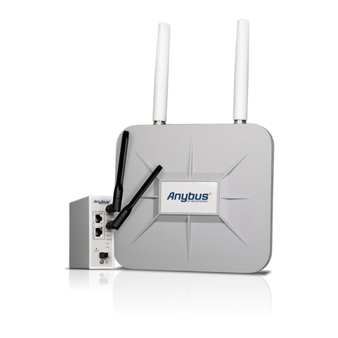
Anybus®Industrial WLAN Access Point
USER MANUAL
SCM-1202-155 1.0 en-US ENGLISH

Important User Information
Disclaimer
The information in this document is for informational purposes only. Please inform HMS Industrial Networks of any
inaccuracies or omissions found in this document. HMS Industrial Networks disclaims any responsibility or liability
for any errors that may appear in this document.
HMS Industrial Networks reserves the right to modify its products in line with its policy of continuous product
development. The information in this document shall therefore not be construed as a commitment on the part of
HMS Industrial Networks and is subject to change without notice. HMS Industrial Networks makes no commitment
to update or keep current the information in this document.
The data, examples and illustrations found in this document are included for illustrative purposes and are only
intended to help improve understanding of the functionality and handling of the product. In view of the wide range
of possible applications of the product, and because of the many variables and requirements associated with any
particular implementation, HMS Industrial Networks cannot assume responsibility or liability for actual use based on
the data, examples or illustrations included in this document nor for any damages incurred during installation of the
product. Those responsible for the use of the product must acquire sufficient knowledge in order to ensure that the
product is used correctly in their specific application and that the application meets all performance and safety
requirements including any applicable laws, regulations, codes and standards. Further, HMS Industrial Networks will
under no circumstances assume liability or responsibility for any problems that may arise as a result from the use of
undocumented features or functional side effects found outside the documented scope of the product. The effects
caused by any direct or indirect use of such aspects of the product are undefined and may include e.g. compatibility
issues and stability issues.
Anybus®Industrial WLAN Access Point User Manual SCM-1202-155 1.0 en-US

Anybus®Industrial WLAN Access Point User Manual SCM-1202-155 1.0 en-US
Table of Contents Page
1 Preface ................................................................................................................................. 3
1.1 About This Document .......................................................................................................3
1.2 Document Conventions.....................................................................................................3
1.3 Trademarks.....................................................................................................................4
2 Safety ................................................................................................................................... 5
2.1 General Safety Instructions................................................................................................5
2.2 Intended Use...................................................................................................................5
3 Preparation.......................................................................................................................... 6
3.1 Support and Resources .....................................................................................................6
4 Installation........................................................................................................................... 7
4.1 Pole Mounting.................................................................................................................7
4.2 Wall Mounting.................................................................................................................8
4.3 DIN Rail Mounting............................................................................................................9
4.4 Connecting Ground Screw .................................................................................................9
4.5 Connecting Access Point IP30 to Power.............................................................................. 10
4.6 Connecting Access Point IP 67 to Power............................................................................. 12
4.7 Connecting to Ethernet ................................................................................................... 13
4.8 Connecting Antennas...................................................................................................... 14
5 Configuration..................................................................................................................... 15
5.1 Before You Begin Configuration........................................................................................ 15
5.2 Accessing the Web Management Interface ......................................................................... 15
5.3 Configure the Country/Region Settings .............................................................................. 16
5.4 Submit and Save Configuration......................................................................................... 16
5.5 Factory Reset ................................................................................................................ 17
5.6 System ......................................................................................................................... 18
5.7 Ethernet Port ................................................................................................................ 21
5.8 Wireless LAN................................................................................................................. 22
5.9 Security........................................................................................................................ 29
5.10 Warning ....................................................................................................................... 33
5.11 Diagnostics ................................................................................................................... 34
5.12 Backup/Restore ............................................................................................................. 36
5.13 Firmware Upgrade ......................................................................................................... 37
5.14 Reset to Default............................................................................................................. 38

Anybus®Industrial WLAN Access Point User Manual SCM-1202-155 1.0 en-US
6 Verify Operation................................................................................................................ 39
7 Technical Data ................................................................................................................... 41
7.1 Technical Specifications................................................................................................... 41
A Wireless Technology Basics .............................................................................................. 43

Preface 3 (44)
1 Preface
1.1 About This Document
This document describes how to install and configure the Anybus Industrial WLAN Access Point.
For additional documentation and software downloads, FAQs, troubleshooting guides and
technical support, please visit www.anybus.com/support.
1.2 Document Conventions
Numbered lists indicate tasks that should be carried out in sequence:
1. First do this
2. Then do this
Bulleted lists are used for:
• Tasks that can be carried out in any order
• Itemized information
►An action
→ and a result
User interaction elements (buttons etc.) are indicated with bold text.
Program code and script examples
Cross-reference within this document: Document Conventions, p. 3
External link (URL): www.hms-networks.com
WARNING
Instruction that must be followed to avoid a risk of death or serious injury.
AVERTISSEMENT
Instruction à suivre pour éviter tout risque de décès ou de blessure grave.
Caution
Instruction that must be followed to avoid a risk of personal injury.
Attention
Instruction à suivre pour éviter tout risque de blessure.
Instruction that must be followed to avoid a risk of reduced functionality and/or damage
to the equipment, or to avoid a network security risk.
Additional information which may facilitate installation and/or operation.
Anybus®Industrial WLAN Access Point User Manual SCM-1202-155 1.0 en-US

Safety 5 (44)
2 Safety
2.1 General Safety Instructions
Caution
Ensure that the power supply is turned off before connecting it to the equipment.
Attention
Assurez-vous que l’alimentation électrique est coupée avant de la brancher sur
l’équipement.
Connecting power with reverse polarity or using the wrong type of power supply may
damage the equipment. Make sure that the power supply is connected correctly and of
the recommended type.
This equipment contains parts that can be damaged by electrostatic discharge (ESD). Use
ESD prevention measures to avoid damage.
2.2 Intended Use
The intended use of this equipment is to provide wireless LAN connectivity. The equipment
receives and transmits data on various physical levels and connection types.
If this equipment is used in a manner not specified by the manufacturer, the protection provided
by the equipment may be impaired.
Anybus®Industrial WLAN Access Point User Manual SCM-1202-155 1.0 en-US

Preparation 6 (44)
3 Preparation
3.1 Support and Resources
For additional documentation and software downloads, FAQs, troubleshooting guides and
technical support, please visit www.anybus.com/support.
Have the product article number available, to search for the product specific support web page. You find
the product article number on the product cover.
Anybus®Industrial WLAN Access Point User Manual SCM-1202-155 1.0 en-US

Installation 7 (44)
4 Installation
4.1 Pole Mounting
Option for access point IP67
1. Use the four included screws and washers to attach the mounting bracket to the access
point.
2. Insert the two included metal bands into the mounting bracket strap slots.
3. Position the metal bands and the mounting bracket on the pole as needed.
4. Tighten the metal bands to the pole and lock them by tightening the screws.
Ensure that the access point is firmly secured to the pole.
Anybus®Industrial WLAN Access Point User Manual SCM-1202-155 1.0 en-US

Installation 8 (44)
4.2 Wall Mounting
Option for access point IP67
1. Use the four included screws and washers to attach the mounting bracket to the access
point.
2. Drill four holes in the wall and insert wall anchors.
3. Use four screws to attach the mounting bracket to the wall.
Anybus®Industrial WLAN Access Point User Manual SCM-1202-155 1.0 en-US

Installation 9 (44)
4.3 DIN Rail Mounting
Option for access point IP30
Fig. 1 DIN rail mounting option
1. Fasten the DIN clip with 3 (M3x6 flat head) screws on the rear side of the access point.
2. Insert the upper end of the DIN rail clip into the DIN rail.
3. Push the bottom of the DIN rail clip into the DIN rail.
4.4 Connecting Ground Screw
Option for access point IP30
To avoid system damage, the equipment should be connected to ground.
Fig. 2
1. Establish a direct connection between the ground screw and the grounding surface prior to
connecting devices.
Anybus®Industrial WLAN Access Point User Manual SCM-1202-155 1.0 en-US

Installation 10 (44)
4.5 Connecting Access Point IP30 to Power
Caution
Ensure that the power supply is turned off before connecting it to the equipment.
Attention
Assurez-vous que l’alimentation électrique est coupée avant de la brancher sur
l’équipement.
Connecting power with reverse polarity or using the wrong type of power supply may
damage the equipment. Make sure that the power supply is connected correctly and of
the recommended type.
4.5.1 Connecting to Power via Terminal Block
Use a power supply of 10-60 VDC for terminal block and 48 VDC for PoE.
Max power consumption: 11.5 W
Fig. 3
P- 10-60 VDC (terminal block)
Max. 11.5 W
P+
1. Insert the positive and negative wires into the P- and P+ contact on the terminal block.
2. Tighten the 2 wire-clamp screws.
3. Connect the power wires to a DC power supply.
Anybus®Industrial WLAN Access Point User Manual SCM-1202-155 1.0 en-US

Installation 12 (44)
4.6 Connecting Access Point IP 67 to Power
Caution
Ensure that the power supply is turned off before connecting it to the equipment.
Attention
Assurez-vous que l’alimentation électrique est coupée avant de la brancher sur
l’équipement.
Connecting power with reverse polarity or using the wrong type of power supply may
damage the equipment. Make sure that the power supply is connected correctly and of
the recommended type.
Fig. 5
Function Power
WAN 1 Gbit/s PoE enabled IEEE 802.3af (48 VDC PoE)
1. Connect the access point to power and an Ethernet network via the WAN/PoE port.
Anybus®Industrial WLAN Access Point User Manual SCM-1202-155 1.0 en-US

Installation 13 (44)
4.7 Connecting to Ethernet
Option for access point IP67
Fig. 6
Port/Function Speed
LAN 1 Gbit/s
1. Connect the access point to an Ethernet network via the LAN port.
Option for access point IP30
Fig. 7
Port Function Speed
1 LAN 1 Gbit/s
1. Connect the access point to an Ethernet network via the LAN port.
Anybus®Industrial WLAN Access Point User Manual SCM-1202-155 1.0 en-US

Installation 14 (44)
4.8 Connecting Antennas
Option for access point IP67
Fig. 8
Placement Type
ANT 1 WLAN 1, N-type connector, female
ANT 2 WLAN 2, N-type connector, female
Option for access point IP30
Fig. 9
Placement Type
ANT 1 WLAN 1, RP-SMA connector, female
ANT 2 WLAN 2, RP-SMA connector, female
Anybus®Industrial WLAN Access Point User Manual SCM-1202-155 1.0 en-US

Configuration 15 (44)
5 Configuration
5.1 Before You Begin Configuration
The access point is configured through web management.
The switch default IP address is http://192.168.10.1/.
The default switch login user name is admin and the password is admin.
5.2 Accessing the Web Management Interface
Prepare for configuring the switch settings via the web management interface.
Before You Begin
►Connect the access point to your computer.
►Connect the access point to power.
►To link your computer with the access point, make sure that the IP address of the computer
is located in the same subnet as the switch default IP address.
Procedure
Access the web management interface:
1. In your browser, type http://IP address and press Enter.
→ The web-based management interface login screen appears.
2. In the login screen, enter user name and password.
3. Click OK.
→ The web-based management interface welcome page appears.
To Do Next
►Configure the access point.
Anybus®Industrial WLAN Access Point User Manual SCM-1202-155 1.0 en-US

Configuration 16 (44)
5.3 Configure the Country/Region Settings
Applicable for the WLAN access point.
To comply with the Radio Equipment Directive (RED) and local radio regulations you must
configure the country/region settings before the access point is brought into use.
Procedure
Configure the Country settings.
In the web management interface:
1. Navigate to the WLAN Settings tab.
2. Select your country/region from the Country drop-down menu.
3. Press Submit button for the setting to take effect.
5.4 Submit and Save Configuration
To apply changes made on a configuration page/tab, click on the Submit button at the bottom of
the page. To discard the changes, click on Cancel. Some pages have additional buttons that are
described in the respective sections in this manual.
To save changed settings permanently, click on Save at the top of the configuration page. The
recent changes will otherwise be discarded if the access point is rebooted.
Fig. 10 Top menu
Anybus®Industrial WLAN Access Point User Manual SCM-1202-155 1.0 en-US

Configuration 17 (44)
5.5 Factory Reset
Reset the access point to its factory settings.
Option for access point IP67
Fig. 11
1. Ensure that the access point is powered on.
2. Remove the cover from the system LEDs and reset button.
3. Press and hold the reset button for >10 seconds.
Option for access point IP30
Fig. 12
1. Ensure that the access point is powered on.
2. Use a pointed object, such as a ballpoint pen, to press and hold the reset button for >10
seconds.
Result
→ Once the reset button is released, the access point reboots automatically.
→ When the access point has successfully rebooted, the SYS LED turns green.
To Do Next for access point IP67
1. Reattach the cover protecting the system LEDs and reset button.
Anybus®Industrial WLAN Access Point User Manual SCM-1202-155 1.0 en-US

Configuration 18 (44)
5.6 System
5.6.1 Information
Fig. 13 System configuration page
System Name Name of the unit
Default: AP
System Description A short description of the unit for easier identification
Default: WLAN AP
Software Version The currently installed firmware version
MAC Address MAC address of the Ethernet network interface
IP Address IP Address of the Ethernet network interface
Subnet Mask Subnet mask of the Ethernet network interface
5.6.2 Login Setting
User Name / Guest Name Names for the normal user account and the guest account
Default: admin/guest
New Password Enter a password for accessing the web interface
Confirm Password Re-type the new password again to confirm it
Setting a secure password for the unit is strongly recommended.
Anybus®Industrial WLAN Access Point User Manual SCM-1202-155 1.0 en-US
Other manuals for Anybus
2
Table of contents
Other HMS Networks Wireless Access Point manuals
Popular Wireless Access Point manuals by other brands
Allied Telesis
Allied Telesis AT-TQ2403 user guide
NETGEAR
NETGEAR WAG102 - ProSafe Dual Band Wireless Access... Specifications
ZyXEL Communications
ZyXEL Communications ZyAIR G-5100 quick start guide
Huawei
Huawei AP5030DN Product description
Space Television
Space Television Arris Space Connect VAP4641 Setup guide
NetComm
NetComm NP730 Technical specifications


