Hobo HOBOnet RXW-WL-900 User manual

HOBOnet® Wireless Sensor Network
HOBOnet Water Level Sensor Interface User Guide
28084-B
This sensor interface, which is compatible with the MX2001 suite of sensors, monitors changing
water levels in a wide range of applications, including streams, lakes, wetlands, tidal areas, and
groundwater. It is designed to work with the HOBOnet (HOBO® RX) Wireless Sensor Network in
which data is transmitted wirelessly from the sensor mote across the network to the station and
then uploaded to HOBOlink® cloud software. With HOBOlink, you can monitor sensor readings,
view graphs, set up alarms, download data, and more.
Specifications
W
ireless Mote
O
perating Temperature
Range
-25° to 60°C (-13° to 140°F) with rechargeable batteries
-40° to 70°C (-40° to 158°F) with lithium batteries
Radio Power 12.6 mW (+11 dBm) non-adjustable
Transmission Range Reliable connection to 457.2 m (1,500 ft.) line of sight at 1.8 m (6 ft.) high
Reliable connection to 609.6 m (2,000 ft.) line of sight at 3 m (10 ft.) high
Wireless Data Standard IEEE 802.15.4
Radio Operating
Frequencies
RXW-WL-900: 904–924 MHz
RXW-WL-868: 866.5 MHz
RXW-WL-921: 921 MHz
RXW-WL-922: 916–924 MHz
Modulation Employed OQPSK (Offset Quadrature Phase Shift Keying)
Data Rate Up to 250 kbps, non-adjustable
Duty Cycle <1%
Maximum Number of
Motes
Up to 50 wireless sensors or 336 data channels per one HOBO RX station
Logging Rate 1 minute to 18 hours
Number of Data Channels 4 (Water Level, Differential Pressure, Water Temperature, Barometric
Pressure)
Battery Type/
Power Source
Two AA 1.2V rechargeable NiMH batteries, powered by built-in solar
panel or two AA 1.5V non-rechargeable lithium batteries for operating
conditions of -40 to 70°C (-40 to 158°F)
Battery Life With NiMH batteries: Typical 3–5 years when used in the temperature
range -20° to 40°C (-4°F to 104°F) and positioned toward the sun (see
Mounting and Positioning the Mote); using the batteries outside this range
reduces the battery life.
With non-rechargeable lithium batteries: 1 year, typical use.
Memory 16 MB
Dimensions Interface Connector Diameter: 25.4 mm (1 inch)
Cable length: 1.83 m (6 ft)
Mote: 16.2 x 8.59 x 4.14 cm (6.38 x 3.38 x 1.63 inches)
Weight 229 g (8.08 oz)
Materials Sensor: Polycarbonate housing encasing epoxy sealed circuit board
Cable: Polyurethane
Mote: PCPBT, silicone rubber seal
Environmental Rating Mote: IP67, NEMA 6
Compliance Marks RXW-WL-900: See last page.
RXW-WL-868: The CE Marking identifies this product as
complying with all relevant directives in the European Union
(EU).
RXW-WL-921: See last page.
RXW-WL-922: See last page.
RXW Water Level Sensor
Models:
•RXW-WL-900 (US)
RXW-WL-868 (Europe)
RXW-WL-921 (Taiwan)
RXW-WL-922 (Australia/NZ)
Included Items:
•Cable ties
•Screws

HOBOnet Water Level Sensor Interface User Guide
U.S. and International Sales: 1-508-759-9500 2 www.onsetcomp.com
Water Level Sensor
Pressure (Absolute) and Water Level Measurements MX2001-01-SS-S and MX2001-01-Ti-S
Operation Range 0 to 207 kPa (0 to 30 psia); approximately 0 to 9 m (0 to 30 ft) of water depth at sea level, or 0 to 12 m (0 to 40 ft) of water
at 3,000 m (10,000 ft) of altitude
Factory Calibrated
Range
69 to 207 kPa (10 to 30 psia), 0° to 40°C (32° to 104°F)
Burst Pressure 310 kPa (45 psia) or 18 m (60 ft) depth
Water Level
Accuracy*
Typical error: ±0.05% FS, 0.5 cm (0.015 ft) water
Maximum error: ±0.1% FS, 1.0 cm (0.03 ft) water
Raw Pressure
Accuracy**
±0.3% FS, 0.62 kPa (0.09 psi) maximum error
Resolution <0.02 kPa (0.003 psi), 0.21 cm (0.007 ft) water
Pressure Response
Time (90%)***
<1 second at a stable temperature
Pressure (Absolute) and Water Level Measurements MX2001-02-SS-S
Operation Range 0 to 400 kPa (0 to 58 psia); approximately 0 to 30.6 m (0 to 100 ft) of water depth at sea level, or 0 to 33.6 m (0 to 111 ft)
of water at 3,000 m (10,000 ft) of altitude
Factory Calibrated
Range
69 to 400 kPa (10 to 58 psia), 0° to 40°C (32° to 104°F)
Burst Pressure 500 kPa (72.5 psia) or 40.8 m (134 ft) depth
Water Level
Accuracy*
Typical error: ±0.05% FS, 1.5 cm (0.05 ft) water
Maximum error: ±0.1% FS, 3.0 cm (0.1 ft) water
Raw Pressure
Accuracy**
±0.3% FS, 1.20 kPa (0.17 psi) maximum error
Resolution <0.04 kPa (0.006 psi), 0.41 cm (0.013 ft) water
Pressure Response
Time (90%)***
<1 second at a stable temperature
Pressure (Absolute) and Water Level Measurements MX2001-03-SS-S
Operation Range 0 to 850 kPa (0 to 123.3 psia); approximately 0 to 76.5 m (0 to 251 ft) of water depth at sea level, or 0 to 79.5 m (0 to 262
ft) of water at 3,000 m (10,000 ft) of altitude
Factory Calibrated
Range
69 to 850 kPa (10 to 123.3 psia), 0° to 40°C (32° to 104°F)
Burst Pressure 1,200 kPa (174 psia) or 112 m (368 ft) depth
Water Level
Accuracy*
Typical error: ±0.05% FS, 3.8 cm (0.125 ft) water
Maximum error: ±0.1% FS, 7.6 cm (0.25 ft) water
Raw Pressure
Accuracy**
±0.3% FS, 2.55 kPa (0.37 psi) maximum error
Resolution <0.085 kPa (0.012 psi), 0.87 cm (0.028 ft) water
Pressure Response
Time (90%)***
<1 second at a stable temperature
Pressure (Absolute) and Water Level Measurements MX2001-04-SS-S and MX2001-04-Ti-S
Operation Range 0 to 145 kPa (0 to 21 psia); approximately 0 to 4 m (0 to 13 ft) of water depth at sea level, or 0 to 7 m (0 to 23 ft) of water
at 3,000 m (10,000 ft) of altitude
Factory Calibrated
Range
69 to 145 kPa (10 to 21 psia), 0° to 40°C (32° to 104°F)
Burst Pressure 310 kPa (45 psia) or 18 m (60 ft) depth
Water Level
Accuracy*
Typical error: ±0.075% FS, 0.3 cm (0.01 ft) water
Maximum error: ±0.15% FS, 0.6 cm (0.02 ft) water
Raw Pressure
Accuracy**
±0.3% FS, 0.43 kPa (0.063 psi) maximum error
Resolution <0.014 kPa (0.002 psi), 0.14 cm (0.005 ft) water
Pressure Response
Time (90%)***
<1 second at a stable temperature
HOBOnet Water Level Sensor Interface User Guide
U.S. and International Sales: 1-508-759-9500 3 www.onsetcomp.com
Barometric Pressure (RXW-WL-xxx)
Operation Range 66 to 107 kPa (9.57 to 15.52 psia)
Temperature
Calibrated Range
-20 to 50°C (-4 to 122°F)
Accuracy ±0.2 kPa (±0.029 psi) over full temperature range at fixed pressure; maximum error ±0.5% FS
Water Level Accuracy* Typical error: ±0.075% FS, 0.3 cm (0.01 ft) water
Maximum error: ±0.15% FS, 0.6 cm (0.02 ft) water
Resolution <0.01 kPa (0.0015 psi)
Response Time <1 second at stable temperature
Stability (Drift) <0.01 kPa (0.0015 psi) per year
T
emperature Measurements (All Sensor End Models MX2001-0x-SS-S and MX2001-0x-Ti-S)
Operation Range -20° to 50°C (-4° to 122°F)
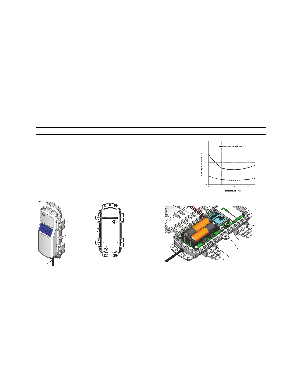
Accuracy ±0.44°C from 0° to 50°C (±0.79°F from 32° to 122°F), see Plot A
Resolution 0.1°C at 25°C (0.18°F at 77°F), see Plot A
Response Time (90%) 5 minutes in water (typical)
Stability (Drift) 0.1°C (0.18°F) per year
* Water Level Accuracy: With accurate reference water level measurement, known water density,
and a stable temperature environment. System Water Level Accuracy equals the sum of the
Barometric Water Level Accuracy plus the selected sensor end Water Level Accuracy.
** Raw Pressure Accuracy: Absolute pressure sensor accuracy includes all sensor drift, temperature,
and hysteresis-induced errors.
*** Changes in Temperature: Allow 20 minutes in water to achieve full temperature compensation of
the pressure sensor. There can be up to 0.5% of additional error due to rapid temperature
changes. Measurement accuracy also depends on temperature response time.
Mote Components and Operation
Sensor Mote Closed, Front Sensor Mote Closed, Back
Sensor Mote Opened
Mounting Tab: Use the tabs at the top and bottom of the mote
to mount it (see Mounting and Positioning the Mote).
Solar Panel: Position the solar panel towards the sun to charge
the batteries (see Mounting and Positioning the Mote).
Sensor Cable: This cable connects the mote to the sensor.
Eyelet: Use this eyelet to attach a 3/16 inch padlock to the
mote for security.
Latch: Use the two latches to open and close the mote door.
Ground Wire Port: Use this port to connect a ground wire (see
Mounting and Positioning the Mote).
Antenna: This built-in antenna provides radio communications
across the RX Wireless Sensor Network.
Mounting
Tab
Solar Panel Latch
Eyelet
Ground Wire
Port
Sensor Cable
Solar Panel Cable
Button
USB Port
Battery Holder
LCD Screen
Antenna
LEDs
Calibration Connection Pins
Vent hole
HOBOnet Water Level Sensor Interface User Guide
U.S. and International Sales: 1-508-759-9500 4 www.onsetcomp.com
LEDs: There are two LEDs to the left of the LCD screen. The
green LED blinks during the process of joining a network,
blinking quickly while the mote searches for a network and
then slowly as the mote registers with the network. Once the
network registration process is complete, the blue LED blinks at
4 seconds to indicate normal operation. If the mote is not
currently part of a network, the blue LED will be off. If the blue
LED is on and not blinking, there is a problem with the mote.
Contact Onset Technical Support.
Solar Panel Cable: This cable connects the built-in solar panel
to the mote circuitry.
Battery Holder: The location where the batteries are installed
as shown (see Battery Information).
Calibration Connection Pins: Use these pins to connect a
programming tool. See Performing a Soil-Specific Calibration for
details.
USB Port: Use this port to connect to the mote to a computer
via USB cable if you need to update the firmware (see Updating
Mote Firmware).
Button: Push this button for 1 second to illuminate the LCD or 3
seconds for the mote to search for a HOBOnet Wireless Sensor
Network to join (see Adding the Mote to the HOBOnet Wireless
Sensor Network).
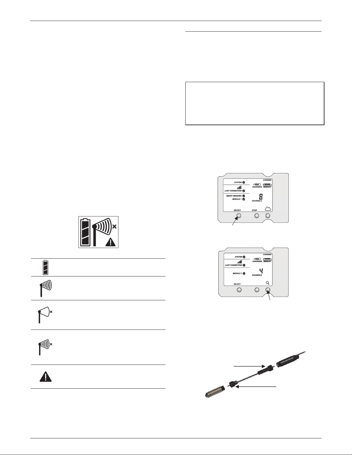
LCD Screen: The mote is equipped with an LCD screen that
displays details about the current status. The following example
shows all symbols illuminated on the LCD screen followed by
definitions of each symbol in the table.
LCD Symbol Description
The battery indicator shows the approximate battery
charge remaining.
This is a signal strength indicator. The more bars, the
stronger the signal between motes. If there is no x
icon next to the signal strength indicator, then the
mote is part of a HOBOnet Wireless Sensor Network.
An empty signal strength icon plus the x icon
indicates that the mote is not currently part of a
network. See Adding the Mote to the HOBOnet
Wireless Sensor Network for details on how to add a
mote to the network.
When the mote is in the process of joining a
network, the signal strength icon will blink and then
the bars in the icon will cycle from left to right. The x
icon will blink during the last step in the network
registration process (see Adding the Mote to the
HOBOnet Wireless Sensor Network for details).
This indicates a problem with the sensor itself (the
mote is operational). Check the sensor and make any
adjustments to it as needed. Contact Onset
Technical Support if the problem persists.
Adding the Mote to the HOBOnet Wireless Sensor
Network
The mote must join a HOBOnet Wireless Sensor Network
before it can begin measuring water level and transmitting
data. This requires that you have access to the RX Station and
the mote at the same time; we recommend that you complete
these steps before deploying the mote.
Important: If you are setting up a new RX Station, follow the
instructions in the station quick start before setting up this
mote (go to www.onsetcomp.com/support/manuals/24380-
man-rx2105-rx2106-qsg for RX2105 and RX2106 stations or go
to www.onsetcomp.com/support/manuals/18254-MAN-QSG-
RX3000 for RX3000 stations).
To add a mote to the network using the RX Station:
1. If the LCD is blank on the station, press any button to wake
it up.
2. Press the Select button once (the number of smart sensors
is displayed above Channels). Press Select again to switch to
the module with the manager.
3. Press the Search button (the magnifying glass). The
magnifying glass icon blinks while the station is searching.
4. Connect the interface connector to the sensor with the
direct-read cable in between as shown here. The end of the
cable with the longer housing connects to the interface
connector as shown below.
5. Open the mote door and install the batteries if you have not
already done so.
Press this button to view the module
Press this button to search for motes to
join the network
Interface
Connector
Plug this part of the cable
with the longer housing into
the interface connector and
screw it to hand tighten.
Plug this part of the cable with the
shorter housing into the sensor
end and screw it to hand tighten.
Sensor end

HOBOnet Water Level Sensor Interface User Guide
U.S. and International Sales: 1-508-759-9500 5 www.onsetcomp.com
6. Press the button on the mote for 3 seconds. The signal
strength icon flashes and then cycles.
7. Watch the LCD on the mote.
The green LED blinks quickly while the mote searches for a
network to join and then blinks slowly while it completes
the network registration. Once the mote has finished
joining the network, the green LED turns off and the blue
LED then blinks indefinitely while the mote is part of the
network.
Note: If the mote cannot find the network or has trouble
remaining connected during this process, make sure the
mote is in a vertical, upright position and within range of
the station.
8. Press the Search button (the magnifying glass) on the
station to stop searching for motes.
If you added more than one more mote to the network, then
the total channel count on the station LCD for the manager
module represents all measurement channels plus a battery
channel for each mote in the network.
Sensor measurements are recorded at the logging interval
specified in HOBOlink, transmitted to the station, and uploaded
to HOBOlink at the next connection interval (readout).
Mounting and Positioning the Sensor Node
•Position the sensor node towards the sun, making sure the
solar panel is oriented so that it receives optimal sunlight
throughout each season. You may need to periodically
adjust the position of the sensor node as the path of the
sunlight changes throughout the year or if tree and leaf
growth alters the amount of sunlight reaching the solar
panel.
•Make sure the sensor node is mounted a minimum of 1.8 m
(6 feet) from the ground or vegetation to help maximize
distance and signal strength.
•Consider using plastic poles such as PVC to mount the
sensor node as certain types of metal could decrease the
signal strength.
•Place the sensor node so there is full line of sight with the
next sensor node. Use a repeater if there is an obstruction
between sensor nodes.
•There should not be more than five sensor nodes in any
direction from a repeater or the manager. Data from sensor
nodes travels or “hops” across the network and may not
reach the station if the sensor node is more than five hops
away.
Deploying the Water Level Sensor
Warning: Do not suspend anything from the 6-foot
cable. The 6-foot cable is not designed to support the
weight of the direct-read cable and sensor.
Press this button again to
stop searching for motes.
Press this button for 3
seconds to have the mote
join the network.
This signal strength icon
blinks while the mote
searches for a network.
Once the mote finds a
network, the icon stops
flashing. The bars cycle
from left to right.
c. d.
This network connection
“x” icon blinks while the
mote completes the
registration process,
which may take up to
five minutes.
Once the mote has finished
joining the network, the “x”
icon disappears and the channel
count on the station LCD
increases by the total channel
count for that sensor model.
a. b.
6-foot cable
This manual suits for next models
3
Table of contents
Other Hobo Recording Equipment manuals


