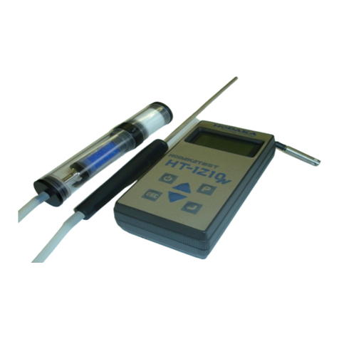
HODAKA HODAKATEST HT-1300Z User manual

HT-1300Z
typeS:
O2,CO,℃
typeA:
O2,CO,NO,℃
typeB:
O2,CO,NO low,℃
typeC:
O2,COhigh,℃
typeD:
O2,CO,NO,NO2,℃
typeE:
O2,NO,NO2,SO2,℃
HODAKA CO., LTD.
1-6-17 Takadono Asahiku
Osaka Japan 535-0031
TEL+81-(0)6-6922-5501 FAX +81-(0)6-6922-5895
Email [email protected]
ver.180801 URL http://www.hodaka-inc.co.jp
Flue gas analyzer
HODAKATEST HT-1300Z
User manual

1.Content 8.3 Operation - Stored data menu 20
8.3.1 Stored data menu
8.3.1.1 View stored No.
1. CONTENT 1 8.3.1.2 Delete stored No. 21
8.3.1.3 Delete stored No. all together
2. INTRODUCTION 3 8.3.1.4 Data in stole 22
2.1 HT-1300Z Flue gas analyzer 8.3.1.5 Data transfer
2.1.1 Function 8.3.1.6 Storage condition 23
2.1.2Purpose 8.4 Operation - Setting menu
2.2 Important instructions regarding the user manual 4 8.4.1 Operation - Setting menu
2.3 Sensor 8.4.1.1 Unit setting
8.4.1.2 Date and time 24
3. SAFETY REGULATIONS 8.4.1.3 Service menu 25
3.1 Safety instructions
8.4.1.4 Service
8.4.1.5 Initial setting
4. DEVICE ILLUSTRATIONS 6 8.5 Print-out 26
4.1 Perspective View
4.2 Connection port 7 9. Calculation 27
4.3 Key board
10. Specification 28
5. POWER SUPPLY 8
11. Condensate trap 30
6. STORAGE
6.1 Operating and storage temperature 12. Message 31
6.2 Long term non-operating and storage
13. Guarantee 31
7. Measurement preparation
7.1 Probe connecting
8. OPERATION 9
8.1 Operation - Basic
8.1.1 Charge
8.1.2 Switch ON the unit 10
8.1.3 Start the measurement
8.1.4 Switch OFF the unit 12
8.2 Operation - Measurement menu 13
8.2.1 Measurement menu
8.2.2 Measurement program selection
8.2.2.1 Program selection
8.2.2.2 CO cut-off 14
8.2.2.3 Fuel type selection
8.2.2.4 Fuel indication setting
8.2.2.5 O2Calculation 15
8.2.3 Measurement point search
8.2.4 Sub menu
8.2.4.1 Sub menu item setting 16
8.2.5 Draft measurement
8.2.5.1 Draft sensor zero setting
8.2.6 Save data 17
8.2.7 View stored data
8.2.8 Pressure measurement 18
8.2.9 Zero setting 19
1 2

・
・
・Pressure measurement
・
Deferential pressure measurement
・Calculation of efficiency, losses and so on.
・
4measurement items /8measurement items indication change(gas measurement)
・Data storage (100 data)
・
Purge-pump for CO sensor protection(option)
・Auto-off function
2.1.2 Purposes
・
Combustion control for oil and gas burners
・
Maintenance for hot water boiler, steam boilers etc.
・
Environmental analysis of incinerators
・
Temperature control of industrial Furness.
・
Flue gas control and maintenance of gas engine and cogeneration facilities
・Control and measurement for other facilities which related to oil and gas combustion
・
・
・
3
4
Temperature measurement of flue gas
2. Introduction
2.1 The flue gas analyzer HT-1300Z
The flue gas analyzer HT-1300Z is used for the following purposes :
2.1.1 Function
Flue gas measurement of O2, CO , NO , NO2, SO2
2.2 Important instructions regarding the user manual
The user manual is an important part of the scope of supply and assures not only the correct operation
and use of the analyzer, but also the safety of the user and the environment.
Several marks are used in this manual. Below are the meaning of each marks.
High risk of decease or injure
Risk of decease or injure
Risk of injure or possessions
have damage.
Advice
2.3 Sensor
Sensor life is very much influenced by frequency in use , gas concentration, condensate. Generally, O2
sensor's life time is approx. 1to 2 years, CO/NO/NO2sensre is approx. 2 to 3 years. Even sensor is not
used, it is exposed by ambient air, so sensor will naturally waste away.
3. SAFETY REGULATIONS
For safe and correct measurement, following safety instructions must be followed very carefully.
3.1 Safety instructions
The analyzer is only to be used with the delivered grip power.
The analyzer is not be used in or under water
After the measurement, vent the analyzer with ambient air and allow the probe to cool.
A hot probe could burn individuals or cause fires in nearby flammable material.
NOTICE
DANGER
DANGER
WARNING

・
・
・
・
・
・
・
・
Exhausted gas through gas out let might
include toxic gas. Do enough ventilation.
・
・
・
Do not see infrared ray.
・
・
・
・
・
・During measurement the gas outlet below the belt clip must not be covered!
Closing gas out let might cause sensor error.
56
The analyzer is NOT explosion protection. Please avoid to use at dangerous area.
Exposed gas from the analyzer during measurement may including poison, therefore please be
careful for ventilation.
Moisture, being pumped out of the condensates trap can be slightly acidic.
In case of skin contact IMMEDIATELY: clean affected parts of the body!
Avoid getting liquid in eyes!
Please carefully clean all parts that were in contact with the condensates.
The metal tube of the probe as well as any other metal parts/accessories are not to be used as
electric conductors.
The metal tube of the probe as well as any other metal/accessories are not to be used as
electric conductors.
The analyzer is not to be placed near or directly exposed to open fire or heat.
Decomposition or remodeling must not be done.
The indicated range of temperature of the probe is not to be exceeded, as the probe,
temperature sensory mechanism and sensor could be destroyed.
The analyzer must not be dropped
The magnet is used at the rare housing. Therefore any precision machine should not be settled
near the analyzer.
After measurement, purge by fresh air, and dry condensate inside analyzer. Also incase filter is
wet or dirty, please replace it.
The analyzer must not be stored at high temperature and high moisture
The exhalations of alcoholic combinations( f. ex. Attenuation, petrol, spirit, varnish・・・) may be
damaged the sensor of the analyzer. Therefore it's forbidden to preserve or use these fluids near
by the device.
During zero setting, probe must be taken off from the chimney and be exposed fresh air.
Zero setting with flue gas may causes sensor error.
Please charge every 3 weeks. During long time storage, battery may discharge and sensor might
be error or stored date might be loose.
For correct measurement, please ask calibration to HODAKA CS center onece a year.
(We recommend to do calibration every 6 months)
4. DEVICE ILLUSTRATIONS
4.1 Perspective View
①
Belt clip
④
Handle strip
⑦
IR interface
②
Magnet
⑤
Buttery cover
③
Gas outlet
⑥
Strap ring
WARNING
NOTICE

Please connect to each connection port as pictures below.
78
4.2 Connection port
5. Power supply
HT-1300Z can be operated by:
・Battery charger (AC100-240V 50/60Hz DC9V 550mA)
・Internal battery (Standard scope of supply / max. 8 hours continues operation (in case back right off) )
①
Flue gas inlet port
④
Ambient air sensor connection port
Printer key
②
Combustion air temperature sensor
connection port
⑤
Pressure measurement port ( Positive
pressure measurement port for differential
pressure measurement)
Function key F3
③
Battery charger connection port
③
PC interface
Function key F2
⑥
Draft pressure measurement port (
Negative pressure measurement port for
differential pressure measurement)
Selection key left
Selection key down
4.3 Key board
Function key F1
OK key / confirmation
Switch ON/OFF key
ESC / cancel key
Selection key right
Submenu key
Selection key up
6. Storage
6.1 Operating and storage temperature
7. Measurement preparation
7.1 Probe connecting
*Ambient air temp. is used to
calculate efficiency and losses
etc. In case this ambient air
temp. sensor is not selected,
main unit views the
temperature value which is
measured by flue gas temp.
sensor of probe as the ambient
air temp.
Operating : +0°C ~ +45°C
Storage : -20°C ~ +50°C
6.2 Long term non-operating and storage
Even switch is off, small quantity of currency is used to keep sensors stable. Battery is also discharge by
itself. So please charge every 3 weeks and check the remaining battery. Keep the device with low battery
voltage might cause battery error or sensor error
Use the HT-2300 only with the HT power supply.DangerNotice Keep dry aria.
Do not storage the HT-2300 with empty battery. In case you
Notice
Use the HT-1300Z only with the HT power supply.
Danger
Notice Keep the device in dry aria.
Do not storage the HT-1300Z with empty battery. In case you
use HT-1300Z after long time storage, do complete discharge,
then do full charge.
Notice
Notice
Option
* for pressure
measurement.
(option)

8.1.1 Charge
Date and time
8.1.3 Star the measurement
No program change
: Measurement starts.
Change the program
( in case the cursor is in the position of 【Gas measurement】 )
910
The mounted sensors types are indicated on the bottom of
window.
After approx. 5 sec., the unit automatically entries to the next
window.
8. OPERATION
8.1 Operation - Basic
After the battery charger is connected, the indication changes
to "Charge battery"
During the battery charger is connected, charge % is indicated.
After battery is fully charged, it changed to trickle charge to
avoid over charge.
A message for zero setting will be indicated.
Once zero setting is finished, calibration mark will be
disappeared.
In case you use same Program No./Fuel/CO limit/O2
calculation value as previous time, is it possible to movie to
measurement window by means of only press F1key.
:「8.2.2 Measurement program selection」3
8.1.2 Switch on the unit
:Switch on the unit
:「8.3.1 Stored data menu」
:「8.4.1 Setting menu」
:Next window
No press OK key; after approx. 8 sec., the unit entries to next
window automatically.
Approx. 30 sec. for zero setting
During calibration, the mark is indicated on left upper side of
the window
:Calibration mark
Zero setting
Remaining battery voltage
It takes approx. 5 hours to charge from zero % to 100%
we recommend that before charge the battery, use all
battery voltage.
blinking
During set to zero, the probe must not come into
contact with the flue gas.
Notice
O2,CO,NO,NO2

Measurement items
Sulfur dioxide
*1()Please do not use these units.
:Print out
:Indicate left window
:[Yes] for switch off
:[No] for NOT switch off
11 12
℃
8.1.4 Switch off the unit
It is possible to switch off at all window.
T.Air
Ambient air temperature
℃
Losses
Losses
%
SOx reference O2(O2=0%)
ppm
SO2refO2
SOx reference O2(O2=?%)
ppm, mg/m3
℃
NOx refO2
NOx reference O2(O2=?%)
ppm, mg/m3
NO2
Nitrogen dioxide
ppm
NOx
Nitrogen oxide
ppm, mg/m3, (mg/kWh, mg/MJ)*1
NOx/0%
NOx reference O2(O2=0%)
ppm
NO/0%
NO reference O2(O2=0%)
ppm
NO refO2
NO reference O2(O2=?%)
ppm, mg/m3
CO refO2
CO reference O2(O2=?%)
ppm, mg/m3, g/m3
NO
Nitrogen monoxide
ppm, mg/m3, (mg/kWh, mg/MJ)*1
Carbon monoxide
ppm, mg/m3, (mg/kWh, mg/MJ)*1
CO
Carbon monoxide
%
CO/0%
CO reference O2(O2=0%)
ppm
Indication
Items
Unit
O2
Oxygen
%
Selected measurement program
Fuel and O2 calculation value
Current page
:switch 4items indication/8 items indication
CO2
Carbon dioxide
%
CO
%
ExAir
:「8.2.5 Draft measurement」
T.Gas
Combustion gas temperature
:page change
:measurement start/stop
SO2
ppm, mg/m3, (mg/kWh, mg/MJ)*1
SO2/0%
:Measurement menu
Excess air
%
Dew point
Dew point
:「8.2.4 Sub menu」
:「8.2.6 Save data」
Effic.
Efficiency
Max.24 measurement items can be indicated
8 items/page total 3 pages
4 items/pages total 6 pages
During measurement the gas outlet below the belt clip must not covered!
Closing gas out let might cause sensor error.
Turn unit
off?
Yes No

8.2 Operation - measurement menu 8.2.2.2 CO cut-off
:change the CO threshold value
8.2.2 Measurement program selection
8.2.2.1 Program selection
:Measurement program selection
:CO measurement Off.
:Back to 「8.2.2.1 Program selection」
8.2.2.3 Fuel type selection
:Move cursor up and down
:Select fuel type then entries measurement window
:Move cursor up and down
8.2.2.4 Fuel indication setting
Only fuels with check mark will be indicated on fuel selected window.
:Move cursor up and down
:Activate / deactivate display of the selected measured value
:「8.2.2.5 O2 reference value setting」
:「8.2.2.3 Fuel type selection」
13 14
If CO concentration exceeds threshold value, CO indication
becomes「----」. (In case the unit does not have purge pump)
:「8.2.2.4 Fuel indication setting」
Can be set up every 100 ppm : 300ppm~3000ppm
Can be set up every 500 ppm : 3000ppm~10000ppm
If CO concentration exceeds threshold value, purge pump
starts work and expose ambient air for protect sensor. (Incase
the unit have purge pump )
8.2.1 Measurement menu
F1:Measurement
F2:Stored data menu
F3:Setting menu
:「8.2.2.2 CO cut-off」
:Select one program among「program1」~「program5」、then
enter to 「8.2.2.3 Fuel selection」
It is possible to store the setting of 「8.2.2.2 CO limit」「8.2.2.3
Fuel selection」「8.2.2.4 Fuel indication setting」「8.2.4.1 Sub
menu item setting」
Fuel type
At the window, except the measurement window, if the
instrument does not be used for more than 30 minutes, the
instrument will be switched off automatically by "auto -off
Fuel type
13A→6C→LPG→kerosine→Light
oil→Heavy A→Heavy C→Pellet
In case select "Test gas",, calculated
items, such as CO2, will not be
calculated.
In case the unit does not have CO
sensor, CO purge pump is not also
mounted.
Purge:CO purge works
Limit over:CO value exceeds the thereshold value.
Range over :CO value eeceeds the measurement
range.

8.2.2.5 O2 Reference value setting 8.2.4.1 Sub menu item setting
:Change O2 reference value :Move cursor up and down
:Change item
:Turn back to initial value
:Stop item selection, move to measurement window
:「8.2.1」 Draft sensor zero setting」
8.2.5 Draft measurement
8.2.3 Central current search
:Fix the draft measurement value
:「8.2.5.1 Draft sensor zero setting」
:Move to measurement window
:After fix the probe, enter to measurement window.
For draft measurement, please attach draft connector to "Draft -" port.
8.2.5.1 Draft sensor zero setting
:Next window
8.2.4 Sub menu
:Move cursor up and down
:「8.2.2.2 CO Cut- off」
(In case cursor position is in [CO cut-off])
:「8.2.4.1 Sub menu item setting」
(in case cursor position is in [page selecting])
:Move to measurement window
15
16
During zero setting, the color of the letter[F3key(zero)] turns
to black.
Slowly insert probe to flue gas , then temperature sensor will
catch the highest temperature.
Once the probe left the highest temperature, alarm sound
becomes to short. Turn probe back to the former position and
fix the probe by the cone.
Max. 115 :The
most highest temp.
Act. 106 :Current
temp. which is
measured by
temperature sensor.
Initial value : Test gas=0%,other items =3%
:「8.2.2.4 Fuel indication setting」
"CO2max" of left window indicates CO2max value of fuel.
The central current search can be switched off on Device
setting
Please ignore "A2" and "B".
After finish zero setting, [F3key(zero)]turns back to normal.
Fuel type
The central current search is the function that to find the
most highest combustible gas temp. In case it is not
necessary, it can be off on 「8.4.1.1 Device setting 」
Draft sensor zero setting must be in the ambient air.
Notice
Zero

8.2.6 Save data
:scroll sites
:Page change
:start measurement
:Confirm the storage position.
:「8.2.5 Draft measurement」
:「8.2.6 Save data」
Program No.
:Move to the measurement window
Date and time
:「8.4.4 Sub menu」
:Print out
8.2.8 Pressure measurement
:Change the value, yes/no
*For differential pressure measurement, optional probe is needed.
:Move cursor
:Move cursor
:Save a data
:Select 「Pressure measurement」, confirm it.
Next window.
Date and time
:Move cursor
8.2.7 View last time data
:Confirm the value which is pointed by cursor.
:Reset all pressure value 1to4 to 0.00hPa
:Move cursor
:Zero setting of pressure sensor.
Next window.
:Select「View last values」,and confirm it.
Next window
:Print out
:Stop pressure measurement, switch to measurement window.
:Stop the zero setting of pressure sensor.
Back to above window.
17 18
Stored No. is shown as left window. You can write over it, but
original data will be deleted.
In case boiler temp.?/ smoke no. is[ yes] on 「8.4.1.1 Device
setting」,left window is indicated.
Oily is indicated, in case smoke no. is Yes, .
Max.4 points of pressure can be measured. Connect a hose to
ΔP+ connection port. For differential pressure measurement,
connect a second hose to Draft - connection port.
After the measurement is stopped by pressing [ESC key], it is
possible to see last time value.
Notice
Notice
Please wait…
Pr
Soot no. and Oily : Please fill out the sampling data
which is taken by smoke tester.(Oily is the adherent
unburned fuel on the filter paper of smoke tester.
Zero setting of pressure sensor must be determined
in ambient air.
Measuremen
t
values
stored
Delete stored
Yes No
Once turn off the unit, last time data will be
cancelled.
Positive pressure

8.2.9 Zero setting 8.3 Operation - Stored data menu
8.3.1 Stored data menu
:Move cursor 8.3.1.1 View stored No.
:Select 「Zero setting」, confirm it. :Move cursor
Next window.
:Select 「View stored sites」, and confirm it.
Next window
:next window
:Select stored sits.
:Move to 「8.3.2 Delete stored sites」
For zero setting, it takes about 30 seconds. :Next window
During zero setting, below mark is indicated.
calibration mark.
:4 lines/8 lines, indication change
:Chang page
:Next window
:Print out
:Next window (boiler temperature / soot no.)
"Oily" is appeared if you select "YES"at Smoke no.
:Move to stored sites selection window
19 20
In case you do not press Okay, after about 8 seconds, it
automatically move to next window.
:Switch it measurement menu window. During zero setting, you
can set other parameters and see stored data.
Left window is appeared only if you select "YES" at Boiler
temp?/Smoke no.? of 「8.4.1.1 Unit setting」
Notice
Please wait…
Pr Delete stored
Yes No
Notice
Zero setting must be determined in ambient air.

8.3.1.2 Delete stored sites 8.3.1.4 Import site data
Please do not use this function.
:Move cursor
:Select 「Delete sites」, and confirm it.
Next window.
:Select the sites to be deleted. 8.3.1.5 Export stored data
:Next window
:Move cursor.
:Select「Export stored data」, confirm it.
Next window
:Delete the sites[Yes]
:Not delete the sites[No]
:Export [Yes]
After delete/not delete, move to previous window.
:Export [Yes]
:Not export[No]
8.3.1.3 Delete all sites
:Move cursor
:Select 「Delete sites」,confirm it
Next window
During data transmission, display becomes like left display.
After the data transmission, stored data menu.
:Delete the sites[Yes]
:Not delete the sites[No]
After delete/not delete, move to previous window.
21 22
If 「Import site data」 is opened by mistake, left window will be
shown. Press[F2key :No], and wait until the window is
automatically switched to stored data menu.
Delete stored
measurement?
Yes No
When you export stored data, please refer to the
manual of Online View 2000 too.
Please wait…

8.3.1.6 Memory occupation
:Switch Japanese and English
:Move cursor
:Back to above window
:Select 「Memory occupation」,confirm it.
Next window.
Current memory occupation is shown.
:Back to window above. Brightness 1~3
Window (4/8)
Boiler temp. ?
Smoke no.?
Measurement point
8.4.1 Operation - Setting menu
8.4.1 Setting menu
8.4.1.1 Unit setting
:Move cursor
8.4.1.2 Set time and date
:Select 「Device settings」, and confirm it.
Next window
:Move cursor
:Select 「Set time and date」, and confirm it.
next window
:Move cursor
:Change values
:Move to next window :Cursor is indicated
:Back to above window :Back to above window
:change number
:Move cursor
:Back to above window
23 24
Setting items
Range
Description
LCD contrast
-14~7
Adjust LCD contrast
Back llight
0 ~ 30minuts
Set the lighting time of back light
Set the brightness of back light
Printer
Unchangeable
-
Signal
On/Off
Key sound On/ Off
4 / 8
Set the measurement item quantity on display
Page
1 / 2 / 3
Set the measurement window pages
Yes/No
Set if it is indicated when store the data
Yes/No
Set if it is indicated when store the data
On/Off
Set if you set measuring point
COM
RS232/Blue.
When using the measurement software, select RS232
cable or Bluetooth.
NOx ratio
1.00~2.50
Set NO2ratio (When NO2sensor is not mounted)
The central current search is the function that to find the
Yes No

8.5 Print out
8.4.1.3 Service menu
Please do not use this function.
8.4.1.4 Service
Please do not use this function.
8.4.1.5 Default config.
Please do not use this function.
25 26
A sample of gas
measurement
A sample of
pressure
If 「Service」 is opened by mistake, left window will be shown.
Press[ESC key] 5times.
If 「Service」 is opened by mistake, left window will be shown.
Press[ESC key] .
If 「Service」 is opened by mistake, left window will be shown.
Press[F3 key] .
date,month,y
date,month,year
hour:minutes:seconds
<Fuel>
13A
6C
LPG
Kerosene
Heavy oil A
Heavy oil C
Pellets
CO2 max. value
O2ref.%
<Measurement items>
T.Gas (℃)
O2(%)
CO2(%)
CO (ppm)
CO(%)
NO (ppm)
NO2(ppm)
SO2(ppm)
NOx (ppm)
T.Air (℃)
Exc.Air
Losses (%)
Effic. (%)
CO/0% (ppm)
COrefO2(ppm))
CO (mg/m3)
NO/0% (ppm)
NOrefO2(ppm)
NO (mg/m3)
NOx/0% (ppm)
NOxrefO2(ppm)
NOx(NO2) (mg/m3)
SO2/0%(ppm)
SO2 refO2(ppm)
SO2(mg/m3)
Dew Point (℃)
Draft (hPa)
T-boiler (℃)
Soot no.1, 2, 3
Oily:(Yes), (No)
For print out, optional infrared
printer (HT-1610) is needed.
Warning Do not see infrared
hour:minutes:seconds
date,month,year

9. Calculation basis
HODAKA TEST® HT-1300Z
Measure- 0~20.9vol%
ment ±0.2vol.%
0.1vol%
with in 20sec.
0~2000ppm (max. over load 10000ppm)
±10ppm or ±5% reading (0~2000ppm)*2
±10% reading (2001~10000ppm)
1 ppm
Within 40sec.(0~2000ppm) Within 60sec.(2001~10000ppm)
0.00~4.00% (max. over load10.00%)
±0.02% or ±5% reading (0.00~2.00%)* 2
±10% reading (2.01~10.00%)
0.01%
Within 60sec.(0.00~2.00%) Within 100sec.(2.01%~10.00%)
0~1000ppm (max. over load 3000ppm)
±5ppm or ±5% reading (0~1000ppm)*2
±10% reading (1001~3000ppm)
1 ppm
Within 40sec.(0~1000ppm) Within 60sec.(1001~3000ppm)
0~200ppm (max.over load 500ppm)
±10ppm (0~200ppm)
±10% reading (201~500ppm)
1 ppm(0.1ppm)*3
Within 60sec.(0~200ppm) Within 100sec.(201~500ppm)
±10% reading (2001~4000ppm)
Resolution 1 ppm
Pressure Measurement range ±100 hPa
Accuracy F.S.±2%
Resolution 0.01 hPa
Combustion air temp. Measurement range 0~650℃ or 0~1100℃
( depend on probe)
Accuracy 0~100℃: ±2℃
100℃~: ±2% reading
Resolution 0.1℃(0~999.9℃) 1℃(1000~1100℃)
Ambient air temp. Measurement range 0~100℃
Fuel data Accuracy ± 2℃
GO AO Resolution 0.1℃
Calculated
CO20~CO2Max (Calculation from O2)
value *4 NOx 0~calculated value
Test gas 0.0 0.0 0.0 0O2reference value 0~calculated value (O2 : Changeable by user)
13A 12.04 10.95 12.2 57 Excess air 1.00~9.99
6C 4.89 4.08 13.1 77 Losses 0~99.9%
LPG 25.9 23.9 13.8 77 0~100%
kerosene 12.15 11.37 15.1 111 Dew point 0~100℃
Light oil 11.9 11.15 15.4 111 mg/m3
Heavy A 11.37 10.68 15.8 111
Heavy C 10.88 10.25 16 111
Pellet 4.63 4.63 20.3 0
27 28
9750
4200
GO:Theoretical flue gas volume, AO:Theoretical air volume, Calp:Lowe calorific value, CO2max:CO2 Max value
of each fuel, fw:Humidity mark
9940
4050
22350
10570
10280
10160
CO2Max
fw
Nm3
Nm3
kcal/Nm3or kcal/kg
0
Calp
O2
Measurement range
Accuracy
Resolution
Response
CO(H2 Compensation)* 1
Measurement range
Accuracy
Resolution
Response
CO very high
Measurement range
Accuracy
Resolution
Response
NO
Measurement range
Accuracy
Resolution
Response
NO low
Measurement range
0~300ppm
Accuracy
±2ppm (0.0~39.9ppm)
±5% reading (40.0~300ppm)
Resolution
0.1 ppm(0.0~99.9ppm) 1ppm (100~300ppm)
Response
Within 40sec.
NO2
Measurement range
Accuracy
Accuracy
±10ppm or ±5% reading (0~2000ppm)*2
Resolution
Response
Within 60sec.(0~2000ppm) Within 100sec.(2001~4000ppm)
SO2
Measurement range
0~2000ppm (max. over load 4000ppm)
Efficiency
Response
*Fuel data might slightly differ
depend on location, therefore
calculated data also might have
difference.
*In case measure sulfur-rich flue
gas, actual dew point might differ
from calculated dew point.
×SO2(ppm/m3)
×SO2(mg/m3)

11. Condensate trap
Fuel 13A, 6C, LPG, Kerosene, Light oil, Heavy A, Heavy C, Pellet
Sensor
galvanic
electrochemical
electrochemical
electrochemical O-ring
electrochemical Star filter
K thermo couple
K thermo couple
Main unit Operating temp. :+0℃ ~ +45℃
Storage temp. :-20℃ ~ +50℃
dot matrix 8items ⇔4items
(W×H×D) 80 x 210 x 60 mm
O-ring
External : Line power (AC100-240V 50/60Hz DC9V 550mA)
Internal : NiMh batteries ( max. 12hours continuous operation)
Standard Built in
Pump, Interface for PC(RS232),CO purge pump*5
equipment Data logger (100data)、interface for printer
-emergency cleaning by using compressed air-
Accessories
Star filter is consumption parts.
Art. No.
air direction
HT-1001 L=300mm φ6mm ~650℃ hose 2700mm
HT-1012*6 L=300mm φ6mm ~650℃ hose 2700mm
Option Probe handle HT-7201SS
HT-7202SS*6
HT-7230
HT-7231
HT-7235
HT-7232 L=750mm φ6mm ~650℃ hose 2700mm
HT-7233 L=750mm φ8mm ~1100℃ hose 2700mm
CO purge pump HT-2321 CO sensor protection
Ambient temperature sensor HT-2305 0~100℃
Probes for K thermo- HT-1251a φ3×130L, 0~950℃, for air/liquids
temperature couple HT-1252a φ1.5×130L, 0~950℃, for air/liquids
HT-1253a φ3×130L, 0~400℃,for air/liquids/food, centric top
HT-1254a 130L, 0~400℃, for surface/rifts/air/liquid
HT-1255a φ4×130L, 0~650℃, for surface/air/liquid
HT-1256a 0~450℃, magnetic probe for surface
HT-1257a 0~180℃, Pliers probe for plates, tube
Pressure sensor unit HT-2303 Pressure, differential pressure, draft pressure
Draft probe HT-1050A L=180mm, φ5mm, hose 3000mm
Attach case HT-2315
Dimension : 340mm×490mm×125mm Weight : 3kg
Measurement software HT-2074 Online View 2000 (Windows7/8.1/10)(with RS232 cable)
Measurement software HT-2084
Blue tooth module*7 HT-1833 For measurement software
Infrared printer HT-1610 1 x printer roll paper, 4 x AAbattery Bad sample:
Roll paper for infrared printer HT-1636 5 Rolls
Be sure that the O-ring proerly put the O-ring is twisted.
slit of the joint.
Bad fitting may cause leakage.
*1 For compensate measured value when measure gas incl. H2.
*2 Accuracy : Which is more higher value is applied as accuracy.
*3 In case NO low sensor is mounted, resolution is 0.1ppm at measurement range 0.0ppm to 99.9ppm
*4 Fuel data might slightly differ depend on location, therefore calculated data also might have difference.
*5 CO sensor non mounted model : CO purge pump is not mounted.
*6 For COhigh/NO2, SO2measurement.
*7 Measurement software (HT-2074) is needed.
Specification will be changed without notice.
29 30
Once the color turns gray,
exchange it.
Online View 2000 (Windows7/8.1/10)(with RS232 cable, USB cable)
(with combustible gas sensor)
L=180mm φ5mm ~650℃ hose 2700mm
L=500mm φ6mm ~650℃ hose 2700mm
Sampling probe (with T-gas sensor)
sampling hose 2700mm
Probe tube
L=300mm φ6mm ~650℃ hose 2700mm
Power supply
Adapter, Probe with sampling hose, Condensate trap, Pressure measurement hose, Soft case,Star filter
Description
Specification
Sampling probe(with T-gas sensor)
Temperature
Display
Dimension
Weight
Approx.680g
CO (CO very high)
NO (NO low)
NO2
SO2
Combustible gas temp.
Ambient air temp.
O2
Take this cap off.
Turn the joint and
take the star filter
out.
Cleaning of moisture
Exchange star filter
Turn the joint, and clear
the moisture.
Loose the star
filter as arrows
above.

12. Message
Condition Battery voltage is too low.
Reason 1 Battery charge is not enough.
Solution
Charge the battery.
Reason 2
AC adapter contact is not good.
Solution Put AC adapter again.
Reason 3 AC adapter's broken wire
Solution Exchange AC adapter
Please ask to HODAKA CO.,LTD. for new wire.
Condition Inner temperature of the unit is too high.
Reason 1 Storage the unit in hot aria.
Solution
Move the unit to cool aria.
Reason 2 Template sensor error.
Solution Please ask to HODAKA CO., LTD. for inspection.
Condition Inner temperature of the unit is too cold.
Reason 1 Storage the unit in cold aria.
Solution
Move the unit to warm aria.
Reason 2 Temperature sensor error.
Solution Please ask to HODAKA CO., LTD. for inspection.
Condition Sensor error
Reason 1 It is sensor life
Solution
Please ask to HODAKA CO., LTD. for inspection.
Reason 2 The unit has been stored without operation.
Solution
Reason 3 Zero setting have done in flue gas.
Solution Do zero setting again in ambient air.
13. Guarantee
31 32
HODAKA CO., LTD.
1-6-17 Asahiku Takadono Osaka Japan 535-0031
TEL: +81-(0)6-6922-5501
FAX: +81-(0)6-6923-1617
Traceability certification can be issued at HODAKA. ( Additional cost will be required)
Charge battery and re-start.
* Left window is the sample of O2 sensor error.
Guarantee period : 12months from date of dispatch.
Guarantee: During guarantee period, if your instrument brakes down although correct usage based on this user
manual, we will repair it by free of charge. In case you have trouble, firstly please contact to HODAKA CO.,
LTD. (+81-(0)6-6922-5501), then send your instrument to HODAKA CO., LTD. International transportation cost
is not include in guarantee.
HODAKA CO., LTD shall not be liable for any loss or damage whatever arising from content errors or any mis-
use of this instrument.
Unit
is to
hot!
Unit
is to
cold!
Low
battery!
Sensor error
O2
This manual suits for next models
6
Table of contents
Other HODAKA Measuring Instrument manuals