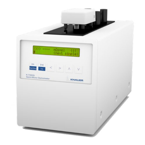
Knauer K-7400S User manual

Freezing Point Osmometer
User Manual
K-7400S Semi-Micro Osmometer

For your own safety, read the manual and always observe the warnings and
safety information on the device and in the manual
Manuel en français: Si jamais vous préfériez un manuel en français pour ce produit, veuillez
vous contacter le support technique (Technical Support) par email ou par
fax avec le no. de série. Merci beaucoup.
Technical Support: Phone: +49 30 809727-111 (9-17h, Central European Time)
Fax: +49 30 8015010
E-Mail: [email protected]
Languages: German, English
Publisher: KNAUER Wissenschaftliche Geräte GmbH
Hegauer Weg 38
D-14163 Berlin
Phone: +49 30 809727-0
Fax: +49 30 8015010
Internet: www.knauer.net
E-Mail: info@knauer.net
Version information: Article number: V3700
Version number: 2.0
Release date: 2017/07/12
Translation of the original edition
The information in this document is subject
to change without prior notice.
For latest version of the manual, check our website:
http://www.knauer.net/knowledge/user-manu-
als.html
Copyright: © KNAUER Wissenschaftliche Geräte GmbH 2017
All rights reserved.

K-7400S user manual V3700
Table of contents
Table of contents
Product information . . . . . . . . . . . . . . . . . . . . . . . . . . . . . . . . . . . . . . . . . . . . . . . . . . . 1
Views . . . . . . . . . . . . . . . . . . . . . . . . . . . . . . . . . . . . . . . . . . . . . . . . . . . . . . . . . . . . . . . . . . . . . . . . . . 1
Front view . . . . . . . . . . . . . . . . . . . . . . . . . . . . . . . . . . . . . . . . . . . . . . . . . . . . . . . . . . . . . . . . . . . 1
Keypad . . . . . . . . . . . . . . . . . . . . . . . . . . . . . . . . . . . . . . . . . . . . . . . . . . . . . . . . . . . . . . . . . . . . . . 1
Rear view . . . . . . . . . . . . . . . . . . . . . . . . . . . . . . . . . . . . . . . . . . . . . . . . . . . . . . . . . . . . . . . . . . . . 2
Scope of delivery . . . . . . . . . . . . . . . . . . . . . . . . . . . . . . . . . . . . . . . . . . . . . . . . . . . . . 2
Safety for users . . . . . . . . . . . . . . . . . . . . . . . . . . . . . . . . . . . . . . . . . . . . . . . . . . . . . . . 2
Signal words . . . . . . . . . . . . . . . . . . . . . . . . . . . . . . . . . . . . . . . . . . . . . . . . . . . . . . . . . . . . . . . . . . . . 3
Decontamination . . . . . . . . . . . . . . . . . . . . . . . . . . . . . . . . . . . . . . . . . . . . . . . . . . . . . . . . . . . . . . . . 3
Symbols and signs . . . . . . . . . . . . . . . . . . . . . . . . . . . . . . . . . . . . . . . . . . . . . . . . . . . . 4
Installation . . . . . . . . . . . . . . . . . . . . . . . . . . . . . . . . . . . . . . . . . . . . . . . . . . . . . . . . . . . 4
Preparations . . . . . . . . . . . . . . . . . . . . . . . . . . . . . . . . . . . . . . . . . . . . . . . . . . . . . . . . . . . . . . . . . . . . 4
Work location . . . . . . . . . . . . . . . . . . . . . . . . . . . . . . . . . . . . . . . . . . . . . . . . . . . . . . . . . . . . . . . . 4
Power supply . . . . . . . . . . . . . . . . . . . . . . . . . . . . . . . . . . . . . . . . . . . . . . . . . . . . . . . . . . . . . . . . 5
Unpacking the device . . . . . . . . . . . . . . . . . . . . . . . . . . . . . . . . . . . . . . . . . . . . . . . . . . . . . . . . . 5
Start-up . . . . . . . . . . . . . . . . . . . . . . . . . . . . . . . . . . . . . . . . . . . . . . . . . . . . . . . . . . . . . . . . . . . . . . . . 6
Switch-on . . . . . . . . . . . . . . . . . . . . . . . . . . . . . . . . . . . . . . . . . . . . . . . . . . . . . . . . . . . . . . . . . . . . . . 6
Operation. . . . . . . . . . . . . . . . . . . . . . . . . . . . . . . . . . . . . . . . . . . . . . . . . . . . . . . . . . . . 7
Connecting the measuring head . . . . . . . . . . . . . . . . . . . . . . . . . . . . . . . . . . . . . . . . . . . . . . . . . . 7
Stand-by position of measuring head . . . . . . . . . . . . . . . . . . . . . . . . . . . . . . . . . . . . . . . . . . . . . . 8
Measurement principle and process . . . . . . . . . . . . . . . . . . . . . . . . . . . . . . . . . . . . . . . . . . . . . . . 8
Switch-on . . . . . . . . . . . . . . . . . . . . . . . . . . . . . . . . . . . . . . . . . . . . . . . . . . . . . . . . . . . . . . . . . . . . . 10
Menu guide . . . . . . . . . . . . . . . . . . . . . . . . . . . . . . . . . . . . . . . . . . . . . . . . . . . . . . . . . . . . . . . . . . . 10
Preparing a measurement . . . . . . . . . . . . . . . . . . . . . . . . . . . . . . . . . . . . . . . . . . . . . . . . . . . . . . . 11
Measurement preparation process . . . . . . . . . . . . . . . . . . . . . . . . . . . . . . . . . . . . . . . . . . . . . 12
Calibration . . . . . . . . . . . . . . . . . . . . . . . . . . . . . . . . . . . . . . . . . . . . . . . . . . . . . . . . . . . . . . . . . . . . 12
Pre-calibration . . . . . . . . . . . . . . . . . . . . . . . . . . . . . . . . . . . . . . . . . . . . . . . . . . . . . . . . . . . . . . . 12
Measurement calibration . . . . . . . . . . . . . . . . . . . . . . . . . . . . . . . . . . . . . . . . . . . . . . . . . . . . . 13
Measuring sample solutions . . . . . . . . . . . . . . . . . . . . . . . . . . . . . . . . . . . . . . . . . . . . . . . . . . . . . 14
Performing a sample measurement . . . . . . . . . . . . . . . . . . . . . . . . . . . . . . . . . . . . . . . . . . . . 14
Important operating notes . . . . . . . . . . . . . . . . . . . . . . . . . . . . . . . . . . . . . . . . . . . . . . . . . . . . . . 15
Functionality tests. . . . . . . . . . . . . . . . . . . . . . . . . . . . . . . . . . . . . . . . . . . . . . . . . . . . . 16
Troubleshooting . . . . . . . . . . . . . . . . . . . . . . . . . . . . . . . . . . . . . . . . . . . . . . . . . . . . . . 16
System messages . . . . . . . . . . . . . . . . . . . . . . . . . . . . . . . . . . . . . . . . . . . . . . . . . . . . . . . . . . . . . . 16
Self-freezing of the sample . . . . . . . . . . . . . . . . . . . . . . . . . . . . . . . . . . . . . . . . . . . . . . . . . . . . . . 17
Non-freezing of the sample . . . . . . . . . . . . . . . . . . . . . . . . . . . . . . . . . . . . . . . . . . . . . . . . . . . . . . 17
Using the EuroOsmo 7400 Software . . . . . . . . . . . . . . . . . . . . . . . . . . . . . . . . . . . . 18
Installation . . . . . . . . . . . . . . . . . . . . . . . . . . . . . . . . . . . . . . . . . . . . . . . . . . . . . . . . . . . . . . . . . . . . 18
Hardware installation . . . . . . . . . . . . . . . . . . . . . . . . . . . . . . . . . . . . . . . . . . . . . . . . . . . . . . . . . 18
Main screen . . . . . . . . . . . . . . . . . . . . . . . . . . . . . . . . . . . . . . . . . . . . . . . . . . . . . . . . . . . . . . . . . . . 19
Icons . . . . . . . . . . . . . . . . . . . . . . . . . . . . . . . . . . . . . . . . . . . . . . . . . . . . . . . . . . . . . . . . . . . . . . . . . 19
Run Settings . . . . . . . . . . . . . . . . . . . . . . . . . . . . . . . . . . . . . . . . . . . . . . . . . . . . . . . . . . . . . . . . . . . 20
Sample list . . . . . . . . . . . . . . . . . . . . . . . . . . . . . . . . . . . . . . . . . . . . . . . . . . . . . . . . . . . . . . . . . . . . 20

K-7400S user manual V3700
Table of contents
Setup . . . . . . . . . . . . . . . . . . . . . . . . . . . . . . . . . . . . . . . . . . . . . . . . . . . . . . . . . . . . . . . . . . . . . . . . . 21
Working parameters . . . . . . . . . . . . . . . . . . . . . . . . . . . . . . . . . . . . . . . . . . . . . . . . . . . . . . . . . . . . 21
Report & Graph . . . . . . . . . . . . . . . . . . . . . . . . . . . . . . . . . . . . . . . . . . . . . . . . . . . . . . . . . . . . . . . . 23
Search function . . . . . . . . . . . . . . . . . . . . . . . . . . . . . . . . . . . . . . . . . . . . . . . . . . . . . . . . . . . . . . . . 23
Maintenance and care . . . . . . . . . . . . . . . . . . . . . . . . . . . . . . . . . . . . . . . . . . . . . . . . . 24
Cleaning the stirring wire and the thermistor . . . . . . . . . . . . . . . . . . . . . . . . . . . . . . . . . . . . . . . 24
Function checks of cooling capacity . . . . . . . . . . . . . . . . . . . . . . . . . . . . . . . . . . . . . . . . . . . . . . 24
Reference thermometer . . . . . . . . . . . . . . . . . . . . . . . . . . . . . . . . . . . . . . . . . . . . . . . . . . . . . . 25
Technical data . . . . . . . . . . . . . . . . . . . . . . . . . . . . . . . . . . . . . . . . . . . . . . . . . . . . . . . . 25
Main features . . . . . . . . . . . . . . . . . . . . . . . . . . . . . . . . . . . . . . . . . . . . . . . . . . . . . . . . . . . . . . . . . . 25
Communication . . . . . . . . . . . . . . . . . . . . . . . . . . . . . . . . . . . . . . . . . . . . . . . . . . . . . . . . . . . . . . . . 25
General . . . . . . . . . . . . . . . . . . . . . . . . . . . . . . . . . . . . . . . . . . . . . . . . . . . . . . . . . . . . . . . . . . . . . . . 26
Repeat orders . . . . . . . . . . . . . . . . . . . . . . . . . . . . . . . . . . . . . . . . . . . . . . . . . . . . . . . . 26
Legal information . . . . . . . . . . . . . . . . . . . . . . . . . . . . . . . . . . . . . . . . . . . . . . . . . . . . . 26
Transport damage . . . . . . . . . . . . . . . . . . . . . . . . . . . . . . . . . . . . . . . . . . . . . . . . . . . . . . . . . . . . . 26
Warranty conditions . . . . . . . . . . . . . . . . . . . . . . . . . . . . . . . . . . . . . . . . . . . . . . . . . . . . . . . . . . . . 27
Declaration of conformity . . . . . . . . . . . . . . . . . . . . . . . . . . . . . . . . . . . . . . . . . . . . . . . . . . . . . . . 27
Disposal . . . . . . . . . . . . . . . . . . . . . . . . . . . . . . . . . . . . . . . . . . . . . . . . . . . . . . . . . . . . . . . . . . . . . . 27
KNAUER Software License Agreement . . . . . . . . . . . . . . . . . . . . . . . . . . . . . . . . . . . . . . . . . . . . 27
Index. . . . . . . . . . . . . . . . . . . . . . . . . . . . . . . . . . . . . . . . . . . . . . . . . . . . . . . . . . . . . . . . 30

K-7400S user manual V3700
1 Product information
Product information
Note: Only use the device for applications that fall within the range of the
intended use. Otherwise, the protective and safety equipment of the
device could fail.
Views
Front view
Keypad
Legend
1Measuring head
2LCD display
3Keypad
Fig. 1 Front view
Buttons Function
START/STOP Starts a measurement or calibration run. If this button
has no specific function on the screen, it causes to return
on the main screen.
With this button, every running measurement can be
interrupted.
VIB Activates the stirring wire. During RUN and CALIBRATE,
the button is without any function.
Arrows Cursor navigation buttons for parameter or value selec-
tion
1
2
3

K-7400S user manual V3700
Scope of delivery 2
Rear view
Scope of delivery
Note: Only use original parts and accessories made by KNAUER or a com-
pany authorized by KNAUER.
Freezing Point Osmometer K-7400S
Power cable
User manual (German/English)
Installation Qualification document ("IQ", English)
RS-232 connection cable
Measuring head
Pack of sample tubes
400 mOsmol/kg calibration solution
850 mOsmol/kg calibration solution
Lint-free cleaning tissue
Safety for users
Professional group The user manual addresses persons who are qualified as chemical labora-
tory technicians or have completed comparable vocational training.
The following knowledge is required:
Knowledge regarding the health risks of chemicals
Participation during an installation of a device or a training by the com-
pany KNAUER or an authorized company.
Safety equipment When working with the device, take measures according to lab regulations
and wear protective clothing:
Safety glasses with side protection
Protective gloves
Lab coat
What must be taken
into account?
All safety instructions in the user manual
The environmental, installation, and connection specifications in the
user manual
Legend
1RS-232 connector
2Measuring head
connector
3Ventilator
4Power switch
5Power connector
Fig. 2 Rear view
5
4
3
2
1

K-7400S user manual V3700
3Safetyforusers
National and international regulations pertaining to laboratory work
Original spare parts and tools made or recommended by KNAUER
Good Laboratory Practice (GLP)
Accident prevention regulations published by the accident insurance
companies for laboratory work
Power cable: Defective power cables are not to be used to connect the
device and the power supply system.
Power strip: If several devices are connected to one power strip, always
consider the maximum power consumption of each device.
Power supply: Only connect devices to voltage sources, whose voltage
equals the device's voltage.
Where is use of the
device prohibited?
Never use the system in potentially explosive atmospheres without appro-
priate protective equipment. For further information, contact the Technical
Support of KNAUER.
Secure decommission-
ing
At any time, take the device completely out of operation by either switch-
ing off the power switch or by pulling the power plug.
Opening the device The device may be opened by the KNAUER Technical Support or any com-
pany authorized by KNAUER only.
Signal words
Possible dangers related to the device are divided into personal and mate-
rial damage in this user manual.
Lethal injuries will occur.
Serious or moderate injuries can occur.
Minor injuries can occur.
Device defects can occur.
Decontamination
Contamination of devices with toxic, infectious or radioactive substances
poses a hazard for all persons during operation, repair, sale, and disposal
of a device.
Life-threatening injuries
Health danger if getting in contact with toxic, infectious or radio-active sub-
stances.
Before disposing of the device or sending it away for repair, you are
required to decontaminate the device in a technically correct manner.
All contaminated devices must be properly decontaminated by a specialist
company or the operating company before they can be recommissioned,
repaired, sold, or disposed of. All materials or fluids used for decontamina-
tion must be collected separately and disposed of properly.
Decontamination
report
Devices without a completed Decontamination Report will not be
repaired. If you would like to return a device to KNAUER, make sure to
enclose a completed Decontamination Report with the device: http://
www.knauer.net/en/downloads/service.html

K-7400S user manual V3700
Symbols and signs 4
Symbols and signs
The following symbols and signs can be found on the device or in the user
manual:
Installation
This chapter describes all preparatory steps prior to start-up.
Preparations
Note: To ensure structural stability, the device is not intended to be
stacked on or below other devices.
Work location
The intended use be ensured only if the requirements for ambient condi-
tions of the operating environment are met. You will find the ambient con-
ditions in the chapter "Technical data" (see page 25).
General Purpose Position the device on a level surface.
Protect the device against direct exposure to sunlight.
Set up the device at a location not exposed to air drafts such as air con-
ditioning systems.
Do not set up the device near to other machines that cause floor vibra-
tions.
Keep the the devices away from high frequency sources. High frequen-
cies may compromise measurement values.
Space requirements At least 5 cm, if there is another device on one side.
At least 10 cm, if there are devices set up on both sides.
At least 15 cm to the cooler fan on the rear.
Ambient temperature The device should not be exposed to major temperature fluctuations
during measurement.
Symbol Meaning
Warning Signs Electric shock hazard
Electrostatic discharge hazard, damages to system,
device, or components can occur.
Biohazard
CE Mark A device or system marked with CE fulfills the product
specific requirements of European directives. This is
confirmed in a Declaration of Conformity.
Note Hints provide useful tips or information worth knowing.

K-7400S user manual V3700
5 Installation
Device defect
The device overheats at exposure to sunlight and insufficient air circula-
tion. Device failures are very likely.
Set up the device in such a way that it is protected against exposure to
direct sunlight.
Keep at least 15 cm clear at the rear and 5–10 cm at each side for air cir-
culation.
Power supply
Use only the enclosed power cable to connect the device to the mains to
make sure that the specifications stated in Technical Data are met. But
check beforehand to use power cables admitted for use in your country.
Replace defective power cables only with accessories from KNAUER.
Detachable power cables must not be replaced with different cable types.
The maximum power input is 70 watts.
Electronic defect
Electronic hazard when using an identically constructed power adapter
from another manufacturer.
Only use original parts and accessories made by KNAUER or a company
authorized by KNAUER.
Note: The nominal capacity of the connected devices must be maximum
50 % of the power supply to account for larger inrush currents when
switching on the modules.
Prerequisites The electrical power supply at the installation site must be connected
directly to the nearest main power line.
The power must be free from ripple, residual current, voltage peaks and
electromagnetic interference.
The connectors for the mains voltage are grounded accordingly.
The device receives sufficient power with reserve capacity.
Power plug The device is intended for use with AC power networks of 100 – 240 V.
Make sure that the power plug on the rear of the device is always acces-
sible, so that the device can be disconnected from the power supply.
To disconnect the device from the main power, disconnect the power
plug.
The osmometer needs a three-core power plug.
Electric shock
Make sure that the power cable is not exposed to high stresses.
The power cable should not be bent or clamped.
Make sure that the power cable does not come in contact with liquids
and heat sources.
Unpacking the device
At the factory, all KNAUER devices are carefully packed for safe transport.
After unpacking, check all device parts and accessories for signs of dam-
age during transport and if necessary assert claims for damages immedi-
ately to the transport company.
The complete listing of consumable and spare parts can be found in sec-
tion "Accessories and spare parts" on page 26.
Prerequisite Check packaging for damage caused during transportation. If necessary,
put forward any claim for damages to the carrier.
Tools Utility knife

K-7400S user manual V3700
Installation 6
Bruising danger
Damage to the device by carrying or lifting it on protruding housing parts.
The device may fall and thus cause injuries.
Lift the device only centrally on the side of the housing.
Process 1. Set up the package in such a way that you can read the label. Using the
utility knife, cut the adhesive tape and open the packaging.
2. Remove the foam insert. Take out the accessory kit and the manual.
3. Open the accessory kit and check the scope of delivery. In case any
parts are missing, contact the Technical Support.
4. Clasp the device from below, lift it out of the packaging and place it on
its feet.
5. Check the device for signs of damage that occurred during transport. In
case you notice any damage, contact the Technical Support.
6. Place the device in its site of operation and remove protective foil.
Next steps Store packaging and keep the included packing list for repeat orders.
Start-up
Note: The device is not suitable for constant operation because it would
reduce the lifespan of the Peltier elements.
Risk of Infection
Risk of infection by injuries caused by a contaminated stirring wire.
Wear safety gloves when handling the measuring head.
Skin Injury
The cooling compartment reaches temperatures up to -30 °C during the
running measurement. Contact with unprotected hands may lead to skin
injuries.
Avoid direct contact with the cooling compartment.
For cleaning or drying, use cotton swabs or a lint-free tissue.
Switch-on
For information and safety instructions for power supply, see page 5.
Electric shock
High voltages build up inside the device, the housing serves as a protec-
tive cover.
Never put the device into operation when the housing is open.
First close the housing, then plug in the power plug and switch the
device on.
Electronic defect
Damage to the electronics if the device is turned on while connecting or
interrupting the power connection.
Switch off the device beforehand.
Prerequisites The device is switched off. The power cable is detached from the power
supply.
Procedure 1. Attach the power cable to the power connector on the rear of the
device.
2. Switch the device on by using the "ON/OFF" switch.
Next Steps Bring the device into operation. To put the device out of operation, switch
off the device and detach the power plug from the power supply.

K-7400S user manual V3700
7Operation
Operation
Connecting the measuring head
Parts of the measuring head are an in-built motor with a stirring wire and
the thermistor as temperature sensor. The measuring head cable is to be
plugged into the connector on the back of the device.
The sample tube, filled with the exact volume of calibration or sample solu-
tion (50 – 150 μl) must be mounted onto the adapter.
Note: Any change of the measuring head causes the need for a precalibra-
tion of the device to adapt the device to the measuring head (see “Pre-cal-
ibration” on page 12).
Legend
1Stirring wire
2Thermistor
3Foot
Fig. 3 Measuring head
Fig. 4 Sample tube
123

K-7400S user manual V3700
Operation 8
The measuring head is placed on the housing plate with the sample tube
rising into the cooling cavity. The device is now ready for measurement.
Note: The sample volume can be reduced down to a volume of 50 μl. It is
important that all calibrations must be performed with exactly the same
volume as the later sample.
Stand-by position of measuring head
Note: Generally the measuring head should be stored with the attached
sample tube.
While working with the osmometer, use the four columns on top of the
device for temporarily set down the measuring head without sample tube.
In the measurement position, it is not necessary that the feet of the measur-
ing head rest on the device.
To avoid sample spilling into the measuring head, it must be held upright.
Measurement principle and process
The osmotic pressure in a solution is proportional to the freezing point
depression of that solution. An aqueous solution, with an osmotic pressure
corresponding to an ideal 1-molal solution, freezes at -1.858 °C. An aque-
ous solution with this freezing point has a concentration of 1 Osmol/kg.
To perform a measurement, the sample solution is cooled down first with-
out stirring. Even pure water can be super-cooled down to about -5
through -8 °C without freezing. The freezing is initiated by an automatically
start of the stirring wire at a set temperature. The temperature reaches the
freezing point, 0 °C in case of pure water (Fig. 6).
Fig. 5 Set-down of the measuring head without sample tube

K-7400S user manual V3700
9Operation
The freezing point of a solution is below 0 °C (Fig. 7). The freezing point
depression ΔT is a measure for the osmolality of a solution. It can be read
directly from the display given in mOsmol/kg.
During a measurement, the actual temperature is displayed. The device
detects the maximum temperature reached, stores it, and if crystallization
occurred satisfactory, displays the result.
After finishing the measurement, the sample tube is warmed up to 20 °C
(stand-by temperature of the device). The measuring head can remain
there before and after measurement as long as desired.
Fig. 6 Temperature-time-curve for pure water
Fig. 7 Temperature-time-curve for a sample solution

K-7400S user manual V3700
Operation 10
Switch-on
While switching on, the device performs an automatic self-test. During this
time, the display presents the start screen with the current firmware version
for a short time.
After completion of the self-test, the display shows the measurement
screen (see Fig. 8 screen 1). The cursor is placed on the rhombus field. As
shown in Fig. 8, it will take you to the relevant menu points.
Menu guide
Starting with the cursor on the rhombus field, further menus become
accessible in an endless loop by pushing the vertical arrow buttons .
By pushing the horizontal arrow buttons , the cursor moves from field
to field. Only those fields are accessible which are allowed to change the
setting. Other fields, like the actual measured temperature, will be
skipped.
On any changeable field the possible settings can be scrolled using the
vertical arrow buttons . The displayed values will be accepted and
stored when leaving the field with one of the horizontal arrow buttons
. In this way, you can e. g. choose between printer and PC for data out-
put (screen 2) or display the measurement data in mOsmol or °C (screen
1).
Fig. 8 Menu path
Screen Explanation
1 Main menu
2 Data Output Controls the connection of the Osmometer with a
printer or PC.
KNAUER V01.XX
Freezing Point Osmometer

K-7400S user manual V3700
11 Operation
Note: Calibration and measurement must be performed at the same set-
tings (freeze & cooling limit). Additionally, an identical sample volume
must be used for measuring and calibration to ensure exact and reproduc-
ible data. As a result, every change of the temperature settings or the sam-
ple volume demands a new calibration.
Preparing a measurement
Note: The device should be switched on at least 5 minutes before use.
To check the stirring wire, press the <VIB> button.
Stab Injury
Risk of injury from vibration wire during function test performance.
Perform the function test with attached sample tube.
Note: If you want to print out the measurement results, you may connect a
printer via RS-232 connector.
The result of each measurement will be printed automatically in the follow-
ing format:
3 TEMP Displays the current temperatures of the sample
and the cooling cavity. Additionally, units can be
changed from [°C] to [°F] with the buttons. If
the sample temperature is displayed with "----",
the measuring head is not connected.
4 INFO Shows the serial number and the current firmware
version.
5 DATE Setting for the date and time. The setting remains
saved when switching off the device.
6 CALIBRATE Displays the calibration points which are currently
in use. There are 3 possible calibration points.
The first field is fixed at "0000". At least 2 calibra-
tion points are necessary for regular measure-
ments. From this screen, the calibrations will be
started (see "Performing the calibration" on
page 13).
7 COOL Sets following parameters, in 0,5°C steps:
Initiation point "freeze" within the range from
-13,0 to -4,0°C.
Minimum temperature "cooling limit" within the
range from -18.0 to -12.0 °C.
8 CALIBRATE-T Enables the pre-calibration to adapt the osmome-
ter to the measuring head, see "Pre-calibration"
on page 12.
Screen Explanation
Measured 0400 mOsmol
23.03.15 08:24:35

K-7400S user manual V3700
Operation 12
After a calibration run, you get the following print:
If a measurement is cancelled due to an error, the screen displays the cor-
responding error message. If a printer is connected, it prints the error mes-
sage, without the specification about the type of error.
Measurement preparation process
Prerequisites The device is switched on and calibrated.
Process 1. Pipet 50 – 150 μl sample or calibration solution into a clean, dry sample
tube.
Note: The sample volume can be freely chosen in the mentioned range. It
is important that you use exactly the same amount for calibration and mea-
surement.
Practical Tip: Please consider, the higher the volume, the better the preci-
sion of the measurement.
2. Put the filled sample tube on the thermistor, so that the thermistor and
the stirring wire dip in the solution. The meniscus of the liquid must be
aligned horizontally.
3. Place the measuring head on top of the device, so that the sample tube
is inserted into the cooling cavity. The feet of the measuring head do
not have to rest on the device.
Next Steps The device is now ready for measurement.
Calibration
Pre-calibration
A pre-calibration is necessary when:
the device is taken into operation the first time.
the measuring head has been replaced.
Prerequisites Prepare a measurement with water (HPLC quality).
Process 1. Select CALIBRATE-T in the osmometer menu (screen 8 in Fig. 8).
2. Push the <START> button. While the pre-calibration is running, the
screen displays the sample temperature and the elapsed time. The run
can be interrupted at any time by pressing the <STOP> button.
3. After finishing the calibration, the screen displays the message
"CALIBRATE-T sample? >successful<". To confirm the calibration press
the <START> button once. Afterwards the initial CALIBRATE-T menu is
displayed and previous calibration values are deleted.
Calibrated 1234 mOsmol
23.03.15 07:36:17
(NO) FREEZE
23.03.15 09:06:04
thermistor > +9.99°C<
00:56

K-7400S user manual V3700
13 Operation
Device Defect
If the sample tube is removed from the measuring head while the sample
or the calibration solution is frozen, the thermistor or the stirring wire can
be damaged.
When the message "next sample" appears on the display, the sample
tube is safe to remove.
Note: Any performed pre-calibration deletes the existing calibration val-
ues.
4. If you get the message "not successful" on the screen at the end of the
pre-calibration, the sample is not frozen. Make sure if
the sample is 0 mOsmol/kg
a valid measuring head is proper connected to the device.
5. Repeat the pre-calibration if necessary.
Measurement calibration
Normally a Two-Point Calibration is sufficient.
Note: Calibrations must be performed very carefully. A confusion of the
calibration solutions will affect all later measurements and leads to incor-
rect results.
Up to 3 calibration points are possible. The desired calibration concentra-
tion can be selected on any of the fields. After that, the calibration run is
started by pressing the <START> button.
The first field is fixed on "0000". On the other fields the choices are ----,
%%%%, 50, 100, 150, up to 1900, 1950, 2000 in steps of 50 mOsmol/kg.
Selecting "----", the corresponding calibration point will be deactivated.
The selection of "%%%%" deactivates all other calibration points (except
"0000"). Simultaneously the displayed measurement results will be shown
in % of this calibration point instead of "mOsmol/kg". The measurement
results are now displayed in % of this calibration value.
Note: At least two calibration points must be active, the "0000" and one of
the others.
The calibration point remains active until a new valid value for the selected
field is created on the CALIBRATE screen. If a calibration run is not success-
fully finished the last calibration value becomes reactivated.
At least 2 calibration points are necessary for regular measurements. To
determine the measurement results, it will be interpolated between the
closest calibration points, or extrapolated from there.
Note: It is recommended to choose the calibration solutions so that the
expected measurement values are situated between the calibration points.
Performing the calibration
Prerequisites Prepare a measurement with water (HPLC quality, see "Measurement
preparation process" on page 12).
Process 1. Activate the CALIBRATE screen and set the first calibration field to
"0000".

K-7400S user manual V3700
Operation 14
2. Push the <START> button. The run can be interrupted at any time by
pressing the <STOP> button. While the calibration is running, the
screen displays the sample temperature and the elapsed time.
3. After the measurement is successfully completed, the measurement
value is displayed.
Push the <START> button for confirmation. An earlier measured calibra-
tion will be overwritten. By pushing any other button, the new value will
be abandoned and the CALIBRATE menu will be shown again.
4. Prepare a measurement with a calibration solution (see "Measurement
preparation process" on page 12). Enclosed to the osmometer are fit-
ting solutions for calibrations with an osmolality of 400 or 850 mOsmol/
kg.
5. Activate the second calibration field on the CALIBRATE screen and set
the osmolality for the calibration solution.
6. Repeat step 2 to 3.
For special applications, especially in the pharmaceutical industry, a Three-
Point Calibration is required. If this is the case, proceed according to the
process above and repeat the process for the calibration field 3.
Re-calibration
A re-calibration is necessary after
replacing the measuring head
changing the temperature settings (see fig. 8 screen 7)
changing the sample volume
Measuring sample solutions
Performing a sample measurement
Prerequisites Prepare a measurement with a sample solution (see "Measurement prepa-
ration process" on page 12).
Process 1. To perform measurements, choose screen 1 (Fig. 8) with the but-
tons and push the <START> button. While the measurement is running,
the screen displays the sample temperature and the elapsed time.
The run can be interrupted any time by pressing the <STOP> button.
2. The device starts the crystallisation automatically and detects the freez-
ing point depression. If the crystallisation occurred properly, it displays
the corresponding osmolality on the display:
The printer output is given in the following format:
0000 mOsmol > +5.43 °C
1:23
0000 mOsmol > -0.00 °C
o.k.? <start>
RUN > -1.23°C
1:23
>>> 1234 mOsmol <<<
<next sample>
Measured 1234 mOsmol
19.03.15 16:05:35

K-7400S user manual V3700
15 Operation
3. Before the next measurement, wait for the sample to unfreeze. This is
shown by the message "next sample" on the display.
If no crystallisation occurs after the automatical start of the stirring wire, the
measurement will be stopped with the following error message:
If the crystallisation occurs before the start of the stirring wire, the measure-
ment will be stopped with the following error message:
Device Defect
If the sample tube is removed from the measuring head while the sample
or the calibration solution is frozen, the thermistor or the stirring wire can
be damaged.
When the message "next sample" appears on the display, the sample
tube is safe to remove.
Note: The sample melting can be quickened by warming up with the fin-
gers. When"next sample" appears below the measurement value, the sam-
ple is unfrozen, and it is save to remove the tube.
Important operating notes
1. The device is only suitable for aqueous solutions.
2. Only use sample tubes which were obtained from KNAUER or recom-
mended by KNAUER. Sample tubes should not be reused.
3. To ensure a fixed sample volume, always introduce the solutions with a
clean and dry pipette tip into the sample tube. Make sure that there are
no air bubbles in the liquid or drops on the tube wall above the liquid.
The sample solution should stand upright in the sample tube.
4. Handle the thermistor always very carefully. Do not use abrasive materi-
als for cleaning. The thermistor should be cleaned occasionally with a
soft tensidic cleaning agent (dilution: 1:10 with water (HPLC quality)
about 40±5 °C). After immersing, activate the stirring function 3 – 5
times for 5 seconds and rinse with water (HPLC quality). The cleaning
frequency depends on the used sample matrix. It is sufficient for pure
saline solutions to rinse the thermistor with the following sample solu-
tion. A dirty thermistor does not give accurate measurement results.
5. Cleaning and drying the thermistor with alcohol or acetone is not rec-
ommended. High-frequency sources may compromise measurement
values. Remaining solvent vapours could cause false results.
6. Solutions containing proteins, such as sera, can only be measured once.
Freezing causes denaturation of the protein. A repetition of the mea-
surement with the same sample would result in increased values.
7. Please note the difference between ideal and real osmolality. Only real
osmolality can be measured. It is not possible to prepare other calibra-
tion solutions by dilution of a calibration solution since the activity coef-
ficient of the solution changes with dilution.
8. Water which is stored in polyethylene bottles over a longer period
could be difficult to be super-cooled. If such difficulties may occur, we
recommend a storage in glass bottles.
9. Make sure that the sample material is homogeneous. If the measure-
ment result has to be reproduced with the same sample, it has to be
> ERROR <
NO FREEZE
> ERROR <
FREEZE

K-7400S user manual V3700
Functionality tests 16
mixed with the stirring wire before each further measurement. As ice
does not contain salines and floats on top while unfreezing, it results in a
concentration gradient which has to be removed before measurement.
10. Evaporation can increase the concentration of dissolved particles
which leads to increase of osmolality of a solution. Calibration solutions
should be used not longer than 30 - 60 min after the tubes were
opened. We recommend using KNAUER calibration solutions which are
mentioned in chapter "Reorders" (see page 26).
11. After finishing all measurements, the osmometer should be switched
off, because a permanent operation reduces the lifespan of the device.
If the device is switched on but unused for a longer period, it may occur
that some water from room air is condensed in the cooling cavity. It
should be removed carefully with a dry, lint-free tissue prior to the next
measurement.
12. The stirring wire triggers the reproducible freezing and is set optimal in
the factory. Make sure that you do not bend the wire while attaching the
sample tubes and cleaning.
Functionality tests
Installation Qualifica-
tion (IQ)
The customer may request the Installation Qualification, which is free of
charge. In case of a request, the Technical Support of KNAUER or from a
provider authorized by KNAUER performs this functionality test during the
installation.
The Installation Qualification is a standardized document that comes as
part of the delivery and includes the following:
confirmation of flawless condition at delivery
check if the delivery is complete
certification on the functionality of the device
Operation Qualifica-
tion (OQ)
The Operation Qualification includes an extensive functionality test
according to KNAUER standard OQ documents. The Operation Qualifica-
tion is a standardized document and free of charge. It is not part of the
delivery, please contact the Technical Support in case of request.
The Operation Qualification includes the following:
definition of customer requirements and acceptance terms
documentation on device specifications
device functionality check at installation site
Test Intervals To make sure that the device operates within the specified range, you
should test the device regularly. The test intervals are dependent on the
usage of the device.
Execution The test can be carried out either by the Technical Support of KNAUER or
from a provider authorized by KNAUER (for a fee).
Troubleshooting
System messages
Any error message will be deleted simply by pressing any button. The
main screen will be displayed.
In any case the first row shows > ERROR < which is specified in the second
row.
Other manuals for K-7400S
2
Table of contents
Other Knauer Measuring Instrument manuals