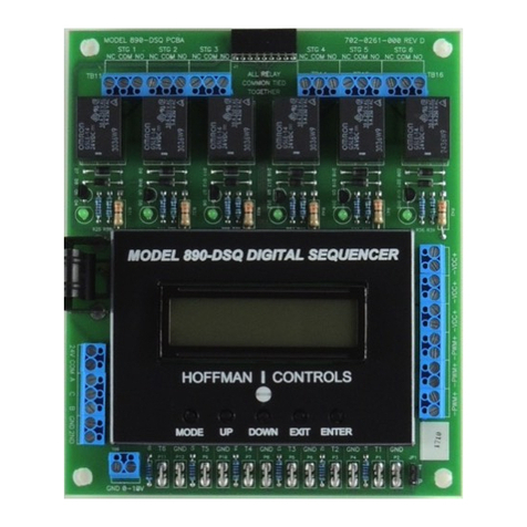
Hoffman Controls 890-DSQ Series Manual

The Class II 890-DSQ microcontroller based universal sequencer
provides a fully programmable platform to sequence multiple
loads using SPDT relay closures. The multiple loads may consist
of condenser fan motors, heating elements, compressors or other
sequencing applications. The 890-DSQ Sequencer's veratility
includes a wide range of input and output options. This universal
sequencer can use 1) up to six (0-5 Vdc) temperature / pressure
sensor inputs or 2) a single 0-10 VDC input. The sequencer has
three 0-10 VDC, EC motor speed control outputs which can be
reconfigured as three 10 - 0 VDC motor speed outputs. There are
also three, 17.5 volt (80Hz) PWM EC motor speed control outputs,
a +5 Vdc output to power the pressure sensors, when used, and up
to six 24 VAC fixed staged outputs, with an additional six 24 VAC
fixed staged outputs available on a separate expansion board (total
of 12 fixed relay output stages).
Hoffman|Controls
Installation & Operating
Instructions
1
Introduction
General
fan. As the input continues to go up, the variable speed fans in-
crease speed until the next fixed speed fan turns on, at which point
the varible speed fan drops in rpm again. This process works in
reverse as the input decreases. Hystesesis is also provided so that no
short cycling of the fixed speed fans occur.
Setpoint Values
The 890-Series sequencers can utilize up to 2 sets of setpoint
values, a primary set and a secondary set. Each set can utilize a
maximum of 12 stage turn on and turn off values (24 set points).
The primary set of setpoint values is the set typically used. The
secondary set of setpoint values can be used, on demand, whenever
the sequencer's "2ND" input terminal is connected to the adjacent
"GND" terminal thru an external contact closure.
The 890 Control consists of a Kydex covered PCB, on stand
offs, with a 32 character LCD display and five push buttons. The
sequencer can be manually operated by following the LCD's menu
system and selecting the available options, parameters and numer-
ical values, using the 5 push buttons. The LCD display routinely
shows a Home Screen and, when selected, up to 5 mode screens
and a small number of additional menu and submenu screens.
The LCD's Home Screen always displays the number of fixed
relay output stages that are turned on and the currently used
input's value (temperature, pressure or 0-10 VDC). When the VS
(variable stage) option is selected, the Home Screen also displays
a speed index (percent) of the continuously variable stage's EC
motors speed or SCRs total output current, along with a number
representing the total of all the relay stages and effective variable
stages (see Mode 1.2, page 4) that are turned on.
Due to the availability of various speed EC motors, the
displayed EC motor speed is shown as a speed index, which is
the percent of full speed (10%, 50%, 76% etc.) that the motor is
operating at. For example: a 1075 rpm EC motor showing a speed
index of 75 (%) would be running at 806 rpm.
The five push buttons (MODE, UP, DOWN, EXIT and
ENTER) allow the installer to change 1) the number of output
stages used, 2) the number of inputs used along with the input
type (temperature, pressure or 0-10 VDC), 3) the selection of the
used output stage's individual (primary & secondary) setpoint
values, 4) the selection of the output stage's activation modes
[LIFO, FIFO or Binary Encode] and 5) the three scaling percent-
ages, used to match the sequencer's PWM and VDC output
signal's parameters, to the variable stage EC motors' input signal's
specifications.
The 890-DSQ Sequencer is available in 4 or 6 fixed stage
models, with each model having an additional "variable stage
output". The variable stage output concists of the "PWM" and
"VDC" outputs and their associated "GND" terminals. There are
three sets of "VDC" outputs and associated "GND" terminals and
three sets of "PWM" (17.5 volt, 80 Hz) outputs and their associ
Description
890-DSQ Series Microprocessor
Based Universal Sequencer
The 890-DSQ can be setup as a traditional sequencer or as a true
continuous vernier sequencer, when using continuously variable
EC motors or SCRs as the (VS) variable stage. The sequencer can
be operated locally, using the 5 push buttons and the information
shown on the LCD screen or remotely using a Modbus RTU master
control.
The 890-DSQ Series sequencers require 24 VAC (1 VA) to
power the control.
IMPORTANT: When using the 890-DSQ Sequencer, select a
transformer to meet the requirements of all the 24 VAC compo-
nents being used.
The 890-DSQ Series sequencer is typically used, in an A/C
system, to sequence multiple condenser fan motors, on and off,
to provide low ambient condenser control. The 890 has up to six
temperature or pressure inputs that are used to sequence up to 12
fixed speed condenser fan motors or other loads.
A unique feature is that the 890 also provides PWM, and either
a 0-10 VDC or 10-0 VDC outputs that are used to drive variable
speed EC fan motors. When the variable speed fans are present,
the sequencer intelligently modifies the output to the variable
speed fans so that, as the additional fixed speed fans are sequenced
on or off, the overall effect is that the total fan outputs' airflow
varies continuously over the entire range.
For example, when the next fixed speed fan is turned on, the
variable speed fans drop in rpm to compensate for the additional
CAUTION
Failure to read and understand the accompa-
nying instructions and diagrams prior to
energizing the sequencer may result in permanent
damage to the sequencer.

2
ated "GND" terminals (12 terminals total).
A total of 9 continuously variable, VDC and/or PWM con-
trolled, EC motors may be wired (in any combination) to the
VDC and/or PWM output terminals. For heating applications, a
maximum of 90 mA is available to operate the SCRs.
The 890-Series sequencer can be used for local, remote or both
local and remote operation. Remote operation can be implemented,
at any time, by using a Modbus RTU master computer to send the
appropriate register data, listed in Table 1, on pages 14 & 15, to the
890-DSQ Series sequencer's internal data registers The sequencer
communicates via a 3 wire Modbus RTU connection to the Modbus
RTU master computer. All of the 890-DSQ Sequencer's options,
parameters and numerical values can be read and set remotely
using the Modbus RTU connection. During remote operation, the
Modbus master reads and writes to the 890-DSQ Sequencer's 76
internal data registers, using Modbus RTU commands 3, 6 and 16
(hexadecimal 10).
The 890-DSQ Sequencers come with a pre-programmed series
of relay output stage setpoint (turn on & off) values. Each one of
the relay's turn on and turn off values may be individually adjusted,
either locally or remotely to suit a particular installation.
When a unique application requires the selection of different
setpoints, other than the pre-programmed setpoints, the new
setpoint values can be automatically calculated by the sequencer's
microcontroller, using equal spacing between stages. Any or all of
the pre-programmed setpoint values can also be updated, manually.
The selection of EC motors depends upon the end use of the EC
motor. When the EC motors will be used as variable stage modu-
lating motors they must be continuously variable EC motors that
accept a 1) 0 - 10 Vdc, or 2) 10 - 0 Vdc or 3) 17.5 volt, 80 Hz
PWM control signal. These continuously variable EC motors do not
need to have the same horsepower and maximum rpm as the fixed
rpm, staged PSC and EC motors. The ratio of max performance
can be set in the controller. However, installing continuously vari-
able EC motors that have the same size, line voltage, horsepower
and maximum rpm as the fixed rpm, staged PSC motors, they are
replacing, makes the installation simpler.
When the EC motors will be used as staging motors they should
provide the same performance (size, line voltage, horsepower and
maximum rpm) as the other staged motors.
When updating a bank of 4 or 6 PSC condenser fan motors to
obtain continuous airflow across the condenser, two of the PSC mo-
tors should be replaced with two continuously variable EC motors,
to supply enough modulating airflow, to achieve continuously
smooth air-flow thru the condenser coils over the sequencer's full
operating range.
When installing the 890-DSQ Sequencer in a heating system, and
the continuous vernier capability will be implemented, size the VS
(variable stage's) SCR with twice the KW capacity as a single fixed
staged heater to ensure continuously smooth heating functionality.
Pre-Installation Information/
Instruction
The 890 sequencer's operation is organized into two sections:
local and remote, with each section containing the same selectable
modes, menus, submenus, settings and numerical values.
The 890-DSQ Sequencer controls its operation by using the
information stored within its microcontroller's 76 internal data
registers. These data registers are numbered from 0 to 75, with each
register's data contents representing a unique sequencer function or
numerical value.
Each 890-DSQ sequencer's microcontroller is programmed, at
the factory, with the internal register data needed for that sequenc-
er's anticipated application. However, the pre-programmed data
can be changed, during or after installation, by manually and/or
remotely updating the microcontroller's internal register data.
Manually updating the internal register data is accomplished by
viewing and then responding to the LCD screen's information and
appropriately pressing one or more of the sequencer's five push
buttons.
Manual operation starts with the LCD's Home Screen (Figure 1,
page 3). The Home Screen displays the number of fixed relay stages
turned on (Stages On: ), along with the selected input type (Tm p ,
PSI or VDC) and that input's present value (Tmp: 53.1).
When selected, the LCD's Home Screen also displays the variable
stage's percent of operation (VS: 75) along with a number repre-
senting the total of all of the fixed relay stages and effective variable
stages that are turned on (2.5). Refer to Mode 1.2, on page 4, for a
description of effective variable stage operation.
The sequencer's MODE button is used to sequentially cycle thru
the LCD screen's 5 available modes. Pressing the MODE but-
ton once advances the LCD's screen to the Change Output Stage
Settings screen (Mode 1). Slowly pressing the MODE button
repeatedly, cycles the sequencer thru its 5 available modes and then
back to the Home Screen.
Remotely updating the 890-DSQ Sequencer's internal register
data requires connecting the sequencer to a Modbus RTU master
computer that can send new register data to, and/or read current
register data from, the 890 microcontroller's internal memory.
NOTE: Since the 890-DSQ's operation is controlled by the data
stored within its internal registers, the sequencer provides the same
identical operation whether the register data is changed locally
(manually) or remotely.
In both local and remote operation the 890-DSQ Sequencer can
be setup to select 1) traditional or continuous VS (variable stage)
operation 2) the number and type of outputs used, 3) the number
and type of inputs used, 4) the primary, and/or secondary setpoint
values used and 5) the Modbus communication parameters.
Operating Methods
IMPORTANT:
When using replacement EC motors, review the system's
current protection device's capability to ensure the protection
devices can handle the much larger in-rush current experienced
during EC motor power up.

3
Local Operation
Local operation uses the control's five push buttons (MODE,
UP, DOWN, EXIT & ENTER) along with the LCD screen's
information to display and select the sequencer's operating modes,
menus, submenus, options and numerical values.
Each mode has several menus, with some menus having a
number of submenus. Each press of the MODE button displays
the next operating mode's title on the LCD screen. Pressing the
ENTER button, while a particular operating mode's screen is
visible on the LCD, displays that mode's first menu. Pressing the
ENTER button again will display the next menu or submenu
associated with that mode. The installer can update the displayed
menu options and/or submenu options and numerical values by
pressing the UP or DOWN buttons.
Whenever a
menu screen
is displayed, each press of the UP
or DOWN buttons incrementally cycles thru that menu's avail-
able options. The UP button advances the displayed options in a
forward direction while the DOWN button does the reverse.
Whenever a
submenu screen
is displayed, each press of the
UP or DOWN buttons incrementally cycles thru that sub-menu's
available options or numerical values. Pressing the UP button
either 1) cycles forward thru the available options or 2) increases
the displayed values. Pressing the DOWN button either 1) cycles
backward thru the available options or 2) decreases the displayed
values.
Once an option or numerical value has been updated, pressing
the ENTER button, again, will save the new value and move the
control's operation forward to the next submenu, menu or mode
.
IMPORTANT:
After updating any information displayed on the LCD's
screen, the installer MUST review ALL of the 890-DSQ
Sequencer's mode, menu, submenu and numerical
value options to 1) ensure that all of the operating
parameters, needed for the application, have been cor-
rectly selected and 2) also ensure that any un-needed or
undesired options or numerical values have not inad-
vertently been left selected.
Pressing the EXIT button, at any time, causes the control to
return immediately to the Home Screen. However, any options
or value changes that were not saved, by previously pressing the
ENTER button, will be lost.
Remote Operation
Remote operation is accomplished by using a Modbus RTU
master computer to communicate with the 890-DSQ Sequencer
via the Modbus 3 wire connection. (The third wire is a common
ground reference). During remote operation, the Modbus RTU
master computer can read the information stored in 74 of the
890-DSQ Sequencer's 76 internal registers (Register 30 is not used
and register 72 is a write only register). Refer to Table 1 (pages
14 & 15) for a complete list of the registers, by number, and the
required data range allowed for each register. The Modbus RTU
master control can also write information to 65 of the 76 sequenc-
er's internal registers (registers 0-29, 31-57 & 68-76). Registers
58 thru 67 are read only registers and therefore ignore any data
written to them (see Modbus Operation section on page 9).
The following information is provided to identify and explain
the 890-DSQ Sequencer's operational modes, menus, submenus,
and numerical value options. The sequencer's MODE button is
used to sequentially cycle thru the 5 available modes displayed on
the sequencer's LCD screen. Pressing the MODE button a sixth
time returns the LCD to the Home Screen.
Figure 1
LCD Home Screen
3TAGES/N
4MP
63
6ARIABLE3TAGES
0ERCENTOFOPERATION
7HEN!CTIVATED
0RESENT4EMPERATURE
0RESSUREOR6OLT$#
)NPUT6ALUE
#OMBINED.UMBEROF
2ELAYAND%FFECTIVE
6ARIABLE3TAGES4URNED
/N
.UMBEROF2ELAY
3TAGES4URNED/N
,#$3CREEN
NOTE:
Continue reading the following "Operating Modes" infor-
mation to become familiar with the 890-DSQ Sequencer's
operating characteristics.
Operating Modes
NOTE:
The Modbus RTU master control can only write data
to 27 of the 890-DSQ Sequencer's registers at a time,
and read data from 29 registers at a time, due to buffer
size limitations in the sequencer's microcontroller.
IMPORTANT:
If any of the down loaded Modbus data is incorrect,
the 890-DSQ Sequencer's microcontroller will change
the incorrect data into software selected default values
during the sequencer's next operating cycle. Therefore,
after updating any data remotely, the operator MUST
allow the 890-DSQ Sequencer to operate over its entire
expected range (°F, PSI or VDC) before reviewing ALL
of the data contained in each of the sequencer's 76
register addresses to 1) ensure that all of the operating
parameters and numerical values, needed for the appli-
cation, have been correctly selected and 2) also ensure
that any unneeded or undesired options or numerical
values have not inadvertently been left selected.

4
MODE 1: Change output stage settings.
The output stage settings can be changed from the pre-
programmed stage options, by pressing the ENTER button
when the above screen appears on the LCD. The LCD
sequence's through the following 4 menu screens with each
press of the ENTER button:
1) Is Variable Stage Used? No
The (VS) variable stage is used (activated) when continu-
ously smooth airflow thru a condenser, or continuously
variable current flow thru a heating system, is desired. Imple-
menting the VS option requires connecting the sequencer's
VDC and/or PWM output(s), to external SCRs or continu-
ously variable speed EC motors. Press the UP or DOWN
button to change the No to a Yes or vice versa. Then press
the ENTER button to save the correct answer and advance
to the LCD screen below.
2) Variable Stage Ratio: 1.0
When the VS (variable stage) above is selected (Yes), this screen
will appear. The variable stage ratio is used to set the ratio of the
total variable stage capacity to that of a single fixed stage. In
order to provide continuously smooth operation when using
hysteresis, the ratio should be greater than 1.
This unique 890-DSQ feature provides PWM and VDC outputs
that are used to drive variable speed EC motor fans or SCRs. When
the variable speed fans or SCRs are present, the sequencer intel-
ligently modifies the output to the variable speed fans or SCRs so
that, as additional fixed speed fans or fixed heaters are sequenced on
and off, the overall effect produces a continuously variable airflow
(or current) over the entire system's range.
A traditional sequencer's operation is shown, as a reference, at
the top of Figure 2 (next column). The 890-DSQ Sequencer's vari-
able stage operation is depicted, on it's own, in the center of Figure
2, while the total sequencer's operation which produces a contin-
uous output, is shown at the bottom of Figure 2.
When the sequencer's stages are activating, the variable speed EC
motor (or SCR) ramps from a low rpm (or current) to full speed (or
full current) before the next sequencer fixed stage turns on. As the
next fixed stage turns on, the variable stage's output immediately
drops down equivalent to one fixed stage. During stage deactivation,
when the previous fixed stage turns off, the variable stage's output
jumps up equivalent to one fixed stage. As the input continues to
decrease, the variable stage's output ramps down equivalent to one
fixed stage just before the, now current, fixed stage turns off. This
combination of fixed stage and variable stage operation produces a
continuously variable (fan rpm or SCR current) output.
Without hysteresis, the variable stage's airflow capacity or SCR's
KW capacity would only need to be a little larger than a fixed A/C
syage's airflow or a fixed heater element's capacity, due to the elec-
tronic components variances in each fixed stage's turn and turn off
tolerances.
With hysteresis, the EC motor's airflow capacity, or SCR's KW
capacity, needs to be much larger than a single fixed stage's on and
off values. The extra capacity provides enough EC motor speed, or
SCR current variation, when more then one fixed stage turns off.
Hysteresis is used to prevent short cycling by using a different on
and off setpoint value.
When the variable stage ratio is more than 1.0, the 890's micro-
controller uses the variable stage ratio's number as the number
of effective stages to to be added to the number of fixed stages
selected. All of these effective stages are activated before the first
fixed stage turns on. The total number of activated, effective and
fixed stages is shown in the LCD screen's upper right corner.
Mathematical Formula
A mathematical formula can be used to calculate the size of
the variable stage's ratio number needed for smooth continuous
operation. This ratio number represents the comparison of the VS
(variable stage's) capacity (airflow or KW) to a fixed stage's airflow
An 890-DSQ Operating Modes Chart (Figure 8, page 13) is
provided to allow the operator to track his/her progress thru the
various LCD's screens. The Operating Modes Chart's information
is viewed starting from the Home Screen, located at the top center
of the chart, and continuing counter clockwise around the chart.
NOTE: The Operating Modes Chart information is presented
in the same mode, menu and submenu order as the information
presented on the LCD screen, when following the chart's informa-
tion in a counter clockwise direction. Press the MODE button to
begin.
'JHVSF
5SBEJUJPOBM7T7BSJBCMF4UBHF0QFSBUJPO
7BSJBCMF4UBHF0QFSBUJPO
8JUI.PUPS3BUJP
/VNCFS
PG7BSJBCMF
4UBHFT0O
5FNQFSBUVSF'
/VNCFSPG
'JYFE&ąFDUJWF
4UBHFT0O
5FNQFSBUVSF'
5FNQFSBUVSF'
5PUBM4UBHFE"JS'MPX
)ZTUFSFTJT
/VNCFSPG
'JYFE4UBHFT0O
5SBEJUJPOBM4FRVFODJOH
8JUI%FHSFFPG)ZTUFSFTJT
7BSJBCMF4UBHF4FRVFODJOH8JUI%FHSFF
PG)ZTUFSFTJTBOE.PUPS3BUJP
5PUBM$POUJOVPVT"JS'MPX
7BSJBCMF4UBHF
)ZTUFSFTJT
3FMBZ4UBHF
0QFSBUJPO

5
or KW capacity. Typical ratios are 1.5 to 2.0 for 4 to 6 stage
applications respectively.
The installer may use the following formula to calculate the
minimum size of the VS (variable stage) ratio:
Variable Stage Ratio = [1+ (the hysteresis value the
difference between stage turn on values)]
Examples:
1) When the hysteresis is 6 °F and the difference between
stage turn on values is also 6 °F, then the
Variable Stage Ratio =[1+(6 °F hysteresis 6 °F )] = 2.0
2) When the hysteresis is 4 °F and the difference between
stage turn on values is 8 °F, then the
Variable Stage Ratio =[1+(4 °F hysteresis 8 °F)] = 1.5
Use the UP and DOWN buttons to change the VS
(variable stage) ratio's number to match the ratio of the
total VS (variable stage) capacity to that of a single fixed
stage. (The range is 1.0 to 12.0). Then press the ENTER
button to store this value and continue to the menu below.
3) Number of used output stages: 6
Use the UP and DOWN buttons to select the number
of relay output stages to be used. The range is 0 to 12
stages. When "0" is selected, only the VS (variable stage's)
EC motors or SCR operation is activated (None of the
fixed relay output stages are used when "0" is selected).
Press the ENTER button when the answer is correct.
4) Stage On Delay in seconds: 2
Use the UP and DOWN buttons to change the delay after
a previous relay stage turns on, until the next relay stage can
turn on. The range is 0.0 to 10.0 seconds. (Entering 0.0 acti-
vates the relay stages as quickly as possible).
MODE 2: Change Input Settings.
In this mode, the number of input stages used, the sensor
combination rule used (see MODE 2.2, next column) and the
Emergency On value can be changed/updated, from the pre-
programmed value, by pressing the ENTER button when the
above screen appears on the LCD.
The LCD sequences thru the following 3 menu screens with
each press of the ENTER button:
1) Number of Inputs Used: 1
There are three types of input options available on the 890-
DSQ Sequencer; temperature sensors, pressure sensors and the
0-10 VDC input. Use the UP and DOWN buttons to set the
number of inputs used. (The range is 0 to 6).
When the number of inputs used is set to "0", the 0-10
VDC input is used instead of the six 0-5 VDC temperature or
pressure sensor inputs. NOTE: The six temperature or pressure
sensor inputs are ignored when the number of inputs is set to
"0".
Press the ENTER button to store the value selected, for the
number of inputs used, and proceed to the submenu below.
2) Input Combination Rule: Maximum
This screen is only displayed when more then a single tem-
perature or pressure sensor input is used. The installer must
choose 1 of 4 possible ways to combine the sensors' input val-
ues. The four choices are; Maximum, Second Highest, Average
or Median.
The Maximum option is chosen when only the highest sen-
sors' input value will be used to control the sequencer's opera-
tion.
The Second Highest option is chosen when only the sec-
ond highest sensor's input value will be used to control the
sequencer's operation.
The Average option is chosen when the numerical average
of all used sensors' input values will be used to control the
sequencer's operation.
The Median option is chosen when the middle value of all
used sensors' input values will be used to control the sequenc-
er's operation.
Use the UP and DOWN buttons to sequentially display
(cycle thru) each of the four combination rules. Then press the
ENTER button when the desired rule is visible on the LCD
screen, to store that combination rule and continue to the
menu below.
3) Emergency On Temp/Pres: 115
This screen appears when temperature or pressure sensor
inputs are selected. If any of the used temperature or pressure
sensor input values reach or exceed the Emergency On value
(max 115 °F or 1000 PSI), all of the remaining inactivated
relay stages will turn on sequentially. Press the ENTER button
to store the selected Emergency On value and continue to the
next mode below.
MODE 3: Change Primary Set points
The primary setpoint values can be changed/updated, from the
pre-programmed setpoint values, by pressing the ENTER button
when the above screen appears on the LCD.
The 890-DSQ Sequencer comes with up to 12 pre programmed
(On/Off) pairs of primary setpoint values. When required by the
application, the installer can change all of the setpoint values auto-
matically (see MODE 3.1 below), or he/she can manually update
any or all of the setpoint values individually (MODE 3.2, page 6).
The stage's turn on and turn off values are associated with one
of the 3 input types; temperature, pressure or 0-10 VDC. The
setpoint values are in °F when the inputs used are temperature
sensors, PSI when the inputs used are pressure sensors or volts DC
when the 0-10 VDC input is used.
The LCD sequences thru the following 3 menu screens with
each press of the ENTER button:
NOTE:
For practical reasons, a VS (variable stage) ratio of 2.0 works
well for A/C condenser banks, containing 4 to 6 fan motors, or
heating systems containing 4 to 6 fixed heating elements.

6
1) Set Stage On/Off
Values Auto? 1
This menu is used to automatically set all of the used stages'
primary on and off values by uniformly distributing the stage's
operation over a selectable span. The selectable span's low and
highvalues are set in the first two submenus below. The third
submenu displays the calculated stage turn on spacing and
resulting stages' hysteresis. The number "1", in this menu's LCD
screen, indicates the primary setpoints can be changed at this time.
Press the ENTER button to start the automatic selection process.
OR
To independently set each stages' on and off values manually,
press the UP or DOWN button once and then press the ENTER
button to advance the LCD's screen to MODE 3.2 below.
a. Low Span Value
Temp/PSI/Volts: 50.0
Use the UP and DOWN buttons to change the low span's value
(number) to match the lowest input value at which the unit will
come on. If the VS (variable stage) has not been selected, this is
the value at which stage 1 turns on. If the VS (variable stage) has
been selected, this is the value at which the EC motors begin to
increase speed from 0 rpm, or the SCR begins supplying current to
the heater.
Press the ENTER button to store the low span's value and
continue to submenu b. below.
b. High Span Value
Temp/PSI/Volts: 80.0
Use the UP and DOWN buttons to change the high span's
value (number) to match the highest input value at which the
unit has all the fixed relay stages on, plus the VS (variable stage)
at 100% (if the VS is being used).
Press the ENTER button to store the high span's value and
continue to submenu c. below.
c. On to On=2.0 Deg/PSI/Volts
Hyster= 1.0 Deg/PSI/Volts
This submenu displays the stage spacing between successive
relay turn on values. This submenu also shows the current hys-
teresis value used for all the activated relay stages.
The first line on the LCD's screen shows the temperature, pres-
sure or voltage difference between successive fixed stage turn on
values, calculated by the microcontroller, using the high and low
span values entered above.
The second line on the LCD's screen shows the current hyster-
esis value (in °F, PSI or volts DC) used for all the selected relay
stages. The operator may change this hysteresis value by pressing
the UP or DOWN buttons until the desired hysteresis value,
used by all the selected (fixed) relay stages, is displayed on the
LCD screen's second line. However, the selectable hysteresis val-
ues are limited due to the span size chosen in MODES 3.1a and
3.1b above.
NOTE: Hysteresis is used to prevent short cycling. It is the
difference between each stage's turn on and turn off values.
Press the ENTER button to save the hysteresis value and
continue to menu 2 below.
2) Set Stage On/Off
Values Manual 1
To set any or all of the primary setpoint's (stage turn on and
turn off) values manually, press the ENTER button.
a. Var Stage TurnOn
Temp/PSI/Volts: 50.0
If VS (variable stage) operation is selected, this screen will
appear. Use the UP and DOWN buttons to set the value at
which the continuously variable EC motors, or SCRs, first begin
to turn on. Press the ENTER button to save the value and con-
tinue to submenu b below.
b. Stage 1 On Temp/PSI/Volts
61.5?
Use the UP and DOWN buttons to set the value at which
relay stage 1 turns on as the input rises. This value must be
above the value at which the variable stage turns on. Otherwise
the stage's turn on value will default to 0.2 (°F, PSI or Vdc)
above the variable stage turn on value (if variable stage is being
used). Press the ENTER button to continue.
c. Stage 1 Off Temp/PSI/Volts
56.0?
Use the UP and DOWN buttons to set the value at which
Stage 1 turns off as the input drops. This value must be below
the value at which Stage 1 turns on. Otherwise, the stage 1 turn
off value will default to 0.1 (°F, PSI or Vdc) below the Stage 1
turn on value. Press the ENTER button to continue.
d. Stage 2 On Temp/PSI/Volts
67.0?
Use the UP and DOWN buttons to set the value at which
Stage 2 turns on as the input rises. This must be above the value
at which Stage 1 turns on. Otherwise the Stage 2 turn on value
will default to 0.2 (°F, PSI or Vdc) above the Stage 1 turn on
value. Press the ENTER button to continue.
Continue to manually set the individual relay stage's on and off
values, as described above, until the number of used output stages'
primary setpoints have been set.
MODE 4: Change Secondary Setpoints
The 890-DSQ Series sequencers include a second set of setpoints
that can be stored and used when an application determined condi-
tion occurs. The sequencer will operate using the secondary set
points when an external contact is closed, connecting the input
terminal labeled "2ND" to the adjacent "GND" terminal. Press the
ENTER button to begin setting the secondary set points.
The LCD screen will show "Set Stage On/Off Values Auto 2".
The "2" indicates the 2nd set of setpoint values can be changed
when this menu is selected. The options available to select these
IMPORTANT:
The installer / remote operator MUST read the
IMPORTANT: boxed text located in the right col-
umn on page 3 of this I&O before continuing with
section "d." below.

7
secondary setpoint values are identical to the options used to set the
primary setpoint values in MODE 3 above. Therefore, follow the
MODE 3 instructions, when the number "2" is present to update
the secondary setpoints using either Auto or Manual methods.
MODE 5: Special Settings:
MODBUS, I&O, RESET
This mode has 9 menus and is used to set the following options:
•Modbus slave's address, baud rate and parity.
•Input sensor type (temperature or pressure).
•Relay stage's sequence mode (FIFO, FILO or Binary
Encode).
•Scale the sequencer's PWM and VDC output signals to
match the variable stage EC motors' full speed, minimum
speed and off percentages
•10 - 0 Vdc output selection (by inverting the PWM and 0-10
VDC output signals).
•Reset the sequencer to factory settings.
The LCD sequences thru the following menu screens with each
press of the ENTER button. Press the ENTER button to begin.
1) MODBUS Address: 1
Use the UP and DOWN buttons to set the Modbus slave
address for this particular 890-DSQ Sequencer. (Range is 1 to
247). Then press the ENTER button to continue.
2) MODBUS Baud Rate
19200
Use the UP and DOWN buttons to select the Modbus
baud rate. (The choices are 1200, 2400, 4800, 9600, 19200,
38400, 57600 and 115200). Then press the ENTER button to
save the selected baud rate and continue.
3) MODBUS Parity
Even
Use the UP and DOWN buttons to set the Modbus par-
ity. (The choices are even parity, odd parity and no parity with
2 stop bits). Then press the ENTER button to save the selected
parity and continue.
4) Change Sensor Type
Temperature
Use the UP and DOWN buttons to change the input sen-
sor type. (Choices are temperature or pressure). When the sensor
type is changed from temperature to pressure, or vice versa, the
Emergency On value is reset to either the temperature based
Emergency On value or the selected maximum pressure value.
Press the ENTER button to save the selected sensor type and
continue. If "pressure" is selected, then another menu appears,
requesting the maximum pressure rating of the sensor used.
Select the appropriate value from 100 PSI to 1000 PSI.
5) Relay Sequence Mode
FILO
Use the UP and DOWN buttons to change the order in which
the relay stages turn on and off. (Choices are FILO, FIFO and
Binary Encode).
FILO mode means the last relay stage to turn on will be the
first relay stage to turn off.
FIFO mode means the first stage to turn on will be the first
stage to turn off. FIFO mode promotes even load operation
(wear) by using each stage an equal amount of time, on average,
by turning on whatever stage has been off the longest and turn-
ing off whatever stage has been on the longest.
Binary Encode
mode uses the Base 2 number counting sys-
tem. Binary encode mode is used when the sequenced loads
are aranged in a 1, 2, 4 weighted ratio (Each load has twice
the capacity of the previous load). This allows the sequencer to
operate 7 stepped loads using only 3 relay output stages (or up
to 12 sequencer loads using 4 relay stages).
Press the ENTER button to save the selected relay sequence and
continue.
6) VarFan SpdLimits OutputHigh: 95
Scales the sequencer's PWM and VDC output signals to match
the selected VS (variable stage) EC motor's full speed control
signal's percentage. For example:
If the EC motor goes to full speed as the input signal rises
to 92% PWM or 9.2 VDC, then the VarFan SpdLimits
OutputHigh: number should be set at 92.
NOTE: The LCD's Home Screen will show "VS: 100" indicat-
ing the EC motor is running at 100% full speed. However, the
PWM and VDC output signals will remain set at 92% PWM
and 9.2 VDC as the sequencer's selected input signal continues
to rise.
7) VarFan SpdLimits OutputLow: 20
Scales the sequencer's PWM and VDC output signals to match
the selected VS (variable stage) EC motor's minimum (low)
speed control signal's percentage. For example:
If the EC motor goes to minimum speed as the motor's input
signal drops to 15% PWM or 1.5 VDC, then the VarFan
SpdLimits OutputLow: number should be set at 15.
NOTE: The LCD's Home Screen will show "VS: 0" indicating
the EC motor is at lowest speed. However, the PWM and VDC
output signals will remain set at 15% PWM and 1.5 VDC,
until the VarFan SpdLimits OutputOff: value is reached (see
menu 8 below).
8) VarFan SpdLimits OutputOff: 0
Scales the sequencer's PWM and VDC output signals to match
the selected VS (variable stage) EC motor's off percentage.
When the sequencer's input temperature (or pressure) sensor
value drops below the EC motor's turn on value (set in MODE
3.1a or 3.2a), the PWM and VDC output signals will linearly
decrease from the VarFan SpdLimits OutputLow: value, to the
VarFan SpdLimits OutputOff: value, over a 2 °F (or 2 PSI)
span, to keep the EC motors from short cycling.
As the input sensor's value continues to decrease, the PWM
and VDC output signals percentage will remain set at the
VarFan SpdLimits OutputOff: value. For example:
1) When the sequencer's VS (variable stage's) output signals
are required to decrease to 0% PWM or 0 VDC to turn off the
fan, the VarFan SpdLimits OutputOff: value must be set to
"0".
2) When the sequencer's VS (variable stage's) output signals are
required to decrease to 5% of their full capability, and remain at
5%, as the input signal continues to decrease, the

contact closure, 3) 0 - 10 VDC input or 4) VS (variable stage) EC
motors) or SCRs).
1.
Wiring must comply with local and national electrical codes.
2.
Disconnect all factory wiring connecting the load (motors,
SCRs etc.) to the line.
3.
Refer to Figure 4, Location of 890-DSQ Sequencer's
Variable Stage Output, for the location of the sequencer's
variable stage's PWM and VDC output terminals.
4.
Refer to Figure 5, 890-DSQ Wiring Diagram 1, for appli-
cations using staged relay outputs with temperature sensor
inputs. Also see Figure 3 (below) for liquid line temperature
sensor mounting.
a.Mount temperature sensor on top of the liquid line where the
line exits the condenser coil.
Figure 3
Liquid Line Temperature Sensor Mounting
b.Fasten sensor firmly,
only using tape
provided. Make sure
the metal tab “heat sink” on the sensor makes firm contact
with the liquid line tubing.
NOTE:
Using hose clamps or tie
wraps to secure the sensor's metal tab to the liquid line will
break the sensor's internal resistor.
Use only the provided
waterproof tape
to secure the sensor to the liquid line.
5. Refer to Figure 6, 890-DSQ Wiring Diagram 2,
for appli-
cations using staged relay outputs with pressure sensor inputs.
6. Refer to Figure 7, 890-DSQ Wiring Diagram 3,
for appli-
cations using Modbus, secondary setpoints, the 0-10 VDC
input, or variable stage EC motors and SCRs.
7. Install and wire the EC motors or SCRs per the manufac-
turers's instructions.
8. Wire the 890-DSQ Sequencer per the wiring diagrams appro-
priate for this installation. More then one wiring diagram's
information may be used, depending upon the application.
NOTE:
Temperature and pressure sensors can not be used
together, as inputs, on the same sequencer.
9. The 890-DSQ Sequencer is designed for low voltage (24 VAC)
operation, including the 24 VAC relay stage output loads.
WARNING:
Disconnect power from the condenser fan motors and
heater SCRs to ensure the motors and SCRs are electri
cally disabled prior to installation.
Installation
NOTE:
The 890-DSQ Sequencer is conformally coated but
must be protected from moisture and condensation if
installed in high humidity areas or outdoors.
IMPORTANT:
Do not install the sequencer in an airtight compartment,
on a vibrating surface or near/on heat generating sources.
&ORh%XTREMEvLOW
!MBIENTSINSULATE
SESNSORWITHMINIMUM
OFvOFvSUCTION
LINEINSULATION
8
VarFan SpdLimits OutputOff: value should be set to "5".
NOTE:
The LCD's Home Screen will continue to show "VS: 0", indi-
cating the EC motor is still off. However, the PWM and VDC
output signals will remain at the PWM and VDC percentages
set by the VarFan SpdLimits OutputOff: value.
10-0 VDC Output Selection
When the variable stage EC motors require a 10-0 VDC con-
trol signal, the VDC output's 0-10 VDC signal can be inverted
(changed to a 10-0 VDC signal) by doing the following: (This
will also invert the PWM duty cycle)
1) Set the VarFan SpdLimits OutputHigh: value to a low num-
ber (usually between 0 and 15).
2) Set the VarFan SpdLimits OutputLow: value to a high num-
ber (usually between 80 and 90).
3) Set the VarFan SpdLimits OutputOff: value to the highest
number (usually between 95 and 100).
For Example:
To set the EC motor's control signal for full speed at 0 Vdc,
minimum speed at 7.7 Vdc and off at 9.5 Vdc, use:
VarFan SpdLimits OutputHigh: 0
VarFan SpdLimits OutputLow: 77
VarFan SpdLimits OutputOff: 95
Using motors with a 10-0 VDC control signal provides a level
of safety. If the EC motors loose their control signal they will
run at full speed.
9) Reset Control To Factory Settings?
No
Use the UP and DOWN buttons to change the No to
a Yes, or vice versa. Then press the ENTER button when the
answer is correct.
The 890-DSQ Series sequencers may be installed using a range
of inputs, staged relay outputs, and continuously variable EC
motors or SCR outputs. Refer to Figures 4 thru 7, (pages 9 thru
12), for the appropriate wiring diagram(s) for this application.
More than one wiring diagram's information may be required
when installing the 1) Modbus connection, 2) secondary setpoint

Built-In Self Test
Sequencer Re-calibration
Modbus Operation
Initial Checkout Procedure
10. When additional cable is required —
a. Always use 22AWG (minimum) stranded, twisted pair cable
properly insulated for outdoor applications.
b. Sensor cables, 0–10 VDC input, Modbus, VDC and PWM
output wires should not run in proximity, or be attached,
to conduit carrying line voltage power wires.
11. This completes the 890-DSQ Sequencer's installation.
• Verify all wire connections are correct for this application.
• Apply 24 VAC power to the 890-DSQ Sequencer.
• Perform all Built-In Self Test instructions below.
• Remove 24 VAC from the sequencer.
The Built-In Self Test function can only be operated in manual
mode, and only simulates a temperature sensor's input value. The
Built-In Self Test allows the installer to use the sequencer's UP and
DOWN buttons to simulate the temperature sensor's input value.
To begin, press and hold the UP and EXIT buttons down
simultaneously for about 1 second. While continuing to hold both
buttons down, press the ENTER button and then release all three
buttons at once. The 890's LCD will display what appears to be
the Home Screen (Figure 1, page 3) and the relays stages may start
turning on, depending on the sequencer's selected setpoint values.
However, the installer can now change the simulated temperature
shown on the LCD screen's second line. Each press of the UP or
DOWN buttons will raise or lower the displayed temperature by 1.0 °F.
The 890-DSQ's operation can be verified by observing each fixed
stage's turn on and turn off temperature, displayed on the LCD's
screen and indicated by each stage's LED. When selected, the VS
(variable stage's) operation can also be verified.
When using the Built-In Self Test function:
1) Verify the fixed relay stages turn on and off at the correct
temperatures, for the application, by observing the LCD
screen's displayed temperature along with each stage's
indicator LED.
2) If selected, verify the 2nd set of setpoints work correctly.
3) If selected, verify the VS (variable stage) EC motors (or
SCRs) turn on and reach full speed (or full current) at
the correct temperatures.
To update any or all of the 890-DSQ Sequencer's mode, menu
and submenu parameters and numerical values remotely, using the
Modbus RTU connection, proceed with the following steps:
• Set MODBUS RTU address, baud rate and parity for each
890-DSQ slave sequencer installed.
• Write to each slave using the TABLE 1 information (pages
14 & 15) to select the 890-DSQ Sequencer's internal
register numbers and associated data, as required, to set
up the sequencer's operating parameters and numerical
values.
NOTE: Reliable operation is obtained only when using
the data values described in the Operating Modes section
(pages 3 thru 7) or shown in Figure 9 (page 13).
• Use Modbus RTU command 3 to read data from indi-
vidual or multiple internal sequencer registers.
• Use Modbus RTU command 6 to write data to an indi-
vidual internal sequencer register.
• Use Modbus RTU command 16 (hexadecimal 10) to write
data to individual or multiple internal sequencer registers.
• Observe the 890-DSQ Sequencer's operation, thru an
entire stsyem's cycle, to ensure correct operation.
If re-calibration of the sequencer's settings or numerical values are
required, due to the particulars of the application, proceed with the
following steps:
1. Power up loads (motors, heating elements etc.) and 890-DSQ
Sequencer.
2. Determine if local, remote or a combination of both local and
remote operation is to be used.
a) When local operation is desired, use the sequencer's 5
push buttons and the LCD screen's information to select the
Continued on last page
IMPORTANT:
The 890-DSQ Sequencer's relay output stages are
only designed for low voltage (24 VAC) operation.
Operating the relay output stages at higher voltages
may result in permanent damage to the sequencer.
9
-PDBUJPOPG%424FRVFODFST
7BSJBCMF4UBHF0VUQVUT
'JHVSF
JP1
TB10 TB5TB4 TB8TB7TB6TB3
5VGND -PWM+-PWM+ -VDC+ -VDC+-VDC+-PWM+
P
T
0
4
'.$607-07-07-6$#6$#6$#
0!24/&
$31
#)2#5)4
"/!2$
03)3%.3/2
6$#
6!2)!",%34!'%
07-6$#
/540543

10
JP1
P13
TB9
P15
P18
P16
P17
SW1 SW2
P21
P19
P20
SW5 SW3
P24
P23
P25
TB10 TB5TB4 TB8TB7
P27
P30
P28
P29
P12P11
K2
P9 P10 P7 P8
K3
P5 P3P6 P4 P2P1
TB6TB3
K6
SW4
TB11TB1
P22
P14
P26
TB2
K4K1
J1
K5
5V
NC NC NC NC
EXIT
NC NC
GND -PWM+-PWM+ -VDC+ -VDC+-VDC+-PWM+
CA24V
0-10VGND
STG 2
P
T
STG 6
2NDGNDBCOM
T6 GND
NOCOMNO
T5 GND T4 GND
DOWNUP
COM NO
T2 GNDT3 GND
ENTER
NOCOM
T1 GND
NO NOCOM
STG 1 STG 5
MODE
COM
MODEL 890-ASQ PCBA
COM
702-0261-000 REV C
6OLT
!CTIVATED
%#-OTOR
VOLT
#OIL
#ONTACTOR
VOLT
#OIL
#ONTACTOR
6!#
-/$% 50 $/7. %8)4 %.4%2
4'.$4'.$4'.$4'.$4'.$4'.$
'.$6
0
4
*0
4%-03%.3/2
03#
-OTOR
03#
-OTOR
,#$
'.$607-07-07-6$#6$#6$#
.##/-./.##/-./
.##/-./ .##/-./.##/-./.##/-./
34'
34'
34' 34'
6#/-!#"'.$.$
%8!-0,%/&$)3#2%4%
03#-/4/27)2).'
,).%
6/,4!'%
4%-03%.3/2
*5-0%24!").
h4v0/3)4)/.
$31
./4%,INE6OLTAGETOCONTACTORS
ISNOTSHOWNFORCLARITY
%428*3*/(%*"(3".
'JHVSF
24.
%8!-0,%/&$)3#2%4%
30%%$%#-/4/2
7)2).'

11
JP1
P13
TB9
P15
P18
P16
P17
SW1 SW2
P21
P19
P20
SW5 SW3
P24
P23
P25
TB10 TB5TB4 TB8TB7
P27
P30
P28
P29
P12P11
K2
P9 P10 P7 P8
K3
P5 P3P6 P4 P2P1
TB6TB3
K6
SW4
TB11TB1
P22
P14
P26
TB2
K4K1
J1
K5
5V
NC NC NC NC
EXIT
NC NC
GND -PWM+-PWM+ -VDC+ -VDC+-VDC+-PWM+
CA24V
0-10VGND
STG 2
P
T
STG 6
2NDGNDBCOM
T6 GND
NOCOMNO
T5 GND T4 GND
DOWNUP
COM NO
T2 GNDT3 GND
ENTER
NOCOM
T1 GND
NO NOCOM
STG 1 STG 5
MODE
COM
MODEL 890-ASQ PCBA
COM
702-0261-000 REV C
6OLT
!CTIVATED
%#-OTOR
VOLT
#OIL
#ONTACTOR
VOLT
#OIL
#ONTACTOR
6!#
-/$% 50 $/7. %8)4 %.4%2
4'.$4'.$4'.$4'.$4'.$4'.$
'.$6
0
4
*0
03#
-OTOR
03#
-OTOR
,#$
'.$607-07-07-6$#6$#6$#
.##/-./.##/-./
.##/-./ .##/-./.##/-./
.##/-./
34'
34'
34' 34'
6#/-!#"'.$.$
%8!-0,%/&$)3#2%4%
03#-/4/27)2).'
6$#
3)'.!,
'.$
6$#
3)'.!,
'.$
03)42!.3$5#%2
03)42!.3$5#%2
,).%
6/,4!'%
*5-0%24!").
h0v0/3)4)/.
$31
24.
./4%,INE6OLTAGETOCONTACTOR
ISNOTSHOWNFORCLARITY
%428*3*/(%*"(3".
'JHVSF
%8!-0,%/&$)3#2%4%
30%%$%#-/4/2
7)2).'

12
-/$"53245
-!34%2#/-054%2
7)2%#/..%#4)/.
48
48
'.$
#534/-%202/6)$%$
3%#/.$!293%40/).4
#/.4!#4#,/352%
%428*3*/(%*"(3".
'JHVSF
JP1
P13
TB9
P15
P18
P16
P17
SW1 SW2
P21
P19
P20
SW5 SW3
P24
P23
P25
TB10 TB5TB4 TB8TB7
P27
P30
P28
P29
P12P11
K2
P9 P10 P7 P8
K3
P5 P3P6 P4 P2P1
TB6TB3
K6
SW4
TB11TB1
P22
P14
P26
TB2
K4K1
J1
K5
5V
NC NC NC NC
EXIT
NC NC
GND -PWM+-PWM+ -VDC+ -VDC+-VDC+-PWM+
CA24V
0-10VGND
STG 2
P
T
STG 6
2NDGNDBCOM
T6 GND
NOCOMNO
T5 GND T4 GND
DOWNUP
COM NO
T2 GNDT3 GND
ENTER
NOCOM
T1 GND
NO NOCOM
STG 1 STG 5
MODE
COM
MODEL 890-ASQ PCBA
COM
702-0261-000 REV C
-/$% 50 $/7. %8)4 %.4%2
4'.$4'.$4'.$4'.$4'.$4'.$
'.$6
0
4
*0
,#$
'.$607-07-07-6$#6$#6$#
.##/-./.##/-./
.##/-./ .##/-./.##/-./
.##/-./
34'
34'
34' 34'
'.$.$
!#"
6#/-
6$#).054
6!2)!",%
6$#
%#-/4/2
6!2)!",%
07-
%#-/4/2
'.$
'.$
07-
6!2)!",%34!'%
%#-/4/23
-/4/23-!8
,).%
6/,4!'%
,).%
6/,4!'%
,).%
6/,4!'%
$31
6$#
/2
6$#
./4%3EE-/$%3ECTIONS
4O3ELECT6$#/UTPUT
6!2)!",%
&2%15%.#9
-/4/2
,).%
6/,4!'%
6
&
$
2
)
6
%

-*/&5:1&-&(&/%
(/-%
3#2%%.
3TAGES/N
4EMP63
-/$%"UTTON
%.4%2"544/.
50OR$/7."UTTON
#HANGE/UTPUT3TAGE3ETTINGS
-/$%"UTTON
)S6ARIABLE3TAGE
5SED9ES
-/$%"UTTON
#HANGE3ECONDARY3ET0OINTS
6ARIABLE3TAGE2ATIO
.UMBEROF&IXED3TAGES5SED
2ANGETO
#HANGE0RIMARY3ET0OINTS
#HANGE)NPUT3ETTINGS
-/$%"UTTON
-/$%"UTTON
2ANGE
)NPUT#OMBINE2ULE
.UMBEROF)NPUTS5SED
-AXIMUM
ND(IGHEST
!VERAGE
-EDIAN
/NTO/N$EG
(YSTER$EG
%MERGENCY/N4EMP0RES6OLTS
2ANGE$EG
03)
6$#
-/$"53
!DDRESS
2ANGETO
%VEN0ARITY
.O0ARITY3TOP"ITS
-/$530ARITY
/DD0ARITY
3PECIAL3ETTINGS-/$"53)/2%3%4
-/$"53"AUD2ATE
-/$%"UTTON
#HANGE3ENSOR4YPE4EMPERTURE
0RESSURE
2ESET#ONTROL4O
&ACTORY3ETS.O
9ES
3TAGES/N$ELAY)N3ECONDS
2ANGE
3TAGE/FF4EMP03)6OLTS
3ET3TAGE/N/FF
6ALUES!UTO
,OW3PAN6ALUE
4EMP03)6OLTS
(IGH3PAN6ALUE
4EMP03)6OLTS
-ANUAL
6AR3TAGE4URN/N
4EMP03)6OLTS
3TAGE/N4EMP03)
6OLTS
3TAGE/FF4EMP
03)6OLTS
3ET3TAGE/N/FF
6ALUES!UTO
,OW3PAN6ALUE
4EMP03)6OLTS
(IGH3PAN6ALUE
4EMP03)6OLTS
-ANUAL
6AR3TAGE4URN/N
4EMP03)6OLTS
3TAGE/N4EMP03)6OLTS
3TAGE/FF4EMP03)6OLTS
3TAGE/FF4EMP
03)6OLTS
/NTO/N$EG
(YSTER$EG
2ELAY3EQUENCE-ODE&)&/
&),/
"INARY%NCODE
2ANGETO
2ANGE
.O
4EST0RESS%NTER
4MP
0RESS50%8)43IMULTANEOUSLY(OLD
$OWN4HEN0RESS%.4%2
50%8)4"UTTONS
#HANGES4EMP03)6$#
%4201&3"5*/(.0%&4$)"35
'JHVSF
63/UTPUT,OW
63/UTPUT/FF
63/UTPUT(IGH
2ANGETO
2ANGETO
2ANGETO
13

14
14
REGISTER
NUMBER 16 BIT REGISTER FUNCTION REGISTER
TYPE
0EC motor or SCR Turn-On Temp,PSI or Volts. (All values times 10) Read & Write
1Stage 1 On Temp(°F),PSI or Volts. (All values times 10) Read & Write
2Stage 2 On Temp(°F),PSI or Volts. (All values times 10) Read & Write
3Stage 3 On Temp(°F),PSI or Volts. (All values times 10) Read & Write
4Stage 4 On Temp(°F),PSI or Volts. (All values times 10) Read & Write
5Stage 5 On Temp(°F),PSI or Volts. (All values times 10) Read & Write
6Stage 6 On Temp(°F),PSI or Volts. (All values times 10) Read & Write
7Stage 7 On Temp(°F),PSI or Volts. (All values times 10) Read & Write
8Stage 8 On Temp(°F),PSI or Volts. (All values times 10) Read & Write
9Stage 9 On Temp(°F),PSI or Volts. (All values times 10) Read & Write
10 Stage 10 On Temp(°F),PSI or Volts. (All values times 10) Read & Write
11 Stage 11 On Temp(°F),PSI or Volts. (All values times 10) Read & Write
12 Stage 12 On Temp(°F),PSI or Volts. (All values times 10) Read & Write
13 Stage 1 Off Temp(°F),PSI or Volts. (All values times 10) Read & Write
14 Stage 2 Off Temp(°F),PSI or Volts. (All values times 10) Read & Write
15 Stage 3 Off Temp(°F),PSI or Volts. (All values times 10) Read & Write
16 Stage 4 Off Temp(°F),PSI or Volts. (All values times 10) Read & Write
17 Stage 5 Off Temp(°F),PSI or Volts. (All values times 10) Read & Write
18 Stage 6 Off Temp(°F),PSI or Volts. (All values times 10) Read & Write
19 Stage 7 Off Temp(°F),PSI or Volts. (All values times 10) Read & Write
20 Stage 8 Off Temp(°F),PSI or Volts. (All values times 10) Read & Write
21 Stage 9 Off Temp(°F),PSI or Volts. (All values times 10) Read & Write
22 Stage 10 Off Temp(°F),PSI or Volts. (All values times 10) Read & Write
23 Stage 11 Off Temp(°F),PSI or Volts. (All values times 10) Read & Write
24 Stage 12 Off Temp(°F),PSI or Volts. (All values times 10) Read & Write
25 Emergency On Temp(°F) or PSI (Both values times 10) Read & Write
26 Variable Stage Ratio (Variable Stage Flow /Fixed Stage Flow) Read & Write
27 Number of Used Stages Read & Write
28 Number of 0-5 VDC Inputs Used (Temperature or Pressure) Read & Write
29 Input Combination Rule: 1=Maximum, 2=Second Highest, 3=Average, 4=Median Read & Write
30 This address number is not used N/A
31 EC motor or SCR [Secondary Setpoint] Turn-On Temp, PSI or Volts. (All values times 10) Read & Write
32 Stage 1 On Temp(°F), PSI or Volts [Secondary Setpoint] (All values times 10) Read & Write
33 Stage 2 On Temp(°F), PSI or Volts [Secondary Setpoint] (All values times 10) Read & Write
34 Stage 3 On Temp(°F), PSI or Volts [Secondary Setpoint] (All values times 10) Read & Write
35 Stage 4 On Temp(°F), PSI or Volts [Secondary Setpoint] (All values times 10) Read & Write
36 Stage 5 On Temp(°F), PSI or Volts [Secondary Setpoint] (All values times 10) Read & Write
37 Stage 6 On Temp(°F), PSI or Volts [Secondary Setpoint] (All values times 10) Read & Write
38 Stage 7 On Temp(°F), PSI or Volts [Secondary Setpoint] (All values times 10) Read & Write
39 Stage 8 On Temp(°F), PSI or Volts [Secondary Setpoint] (All values times 10) Read & Write
40 Stage 9 On Temp(°F), PSI or Volts [Secondary Setpoint] (All values times 10) Read & Write
41 Stage 10 On Temp(°F), PSI or Volts [Secondary Setpoint] (All values times 10) Read & Write
MODBUS Registers for the 890-DSQ Sequencer
TABLE 1

15
REGISTER
NUMBER 16 BIT REGISTER FUNCTION REGISTER
TYPE
42 Stage 11 On Temp(°F), PSI or Volts [Secondary Setpoint] (All values times 10) Read & Write
43 Stage 12 On Temp(°F), PSI, Volts [Secondary Setpoint] (All values times 10) Read & Write
44 Stage 1 Off Temp(°F), PSI, Volts [Secondary Setpoint] (All values times 10) Read & Write
45 Stage 2 Off Temp(°F), PSI, Volts [Secondary Setpoint] (All values times 10) Read & Write
46 Stage 3 Off Temp(°F), PSI, Volts [Secondary Setpoint] (All values times 10) Read & Write
47 Stage 4 Off Temp(°F), PSI, Volts [Secondary Setpoint] (All values times 10) Read & Write
48 Stage 5 Off Temp(°F), PSI, Volts [Secondary Setpoint] (All values times 10) Read & Write
49 Stage 6 Off Temp(°F), PSI, Volts [Secondary Setpoint] (All values times 10) Read & Write
50 Stage 7 Off Temp(°F), PSI, Volts [Secondary Setpoint] (All values times 10) Read & Write
51 Stage 8 Off Temp(°F), PSI, Volts [Secondary Setpoint] (All values times 10) Read & Write
52 Stage 9 Off Temp(°F), PSI, Volts [Secondary Setpoint] (All values times 10) Read & Write
53 Stage 10 Off Temp(°F), PSI, Volts [Secondary Setpoint] (All values times 10) Read & Write
54 Stage 11 Off Temp(°F), PSI, Volts [Secondary Setpoint] (All values times 10) Read & Write
55 Stage 12 Off Temp(°F), PSI, Volts [Secondary Setpoint] (All values times 10) Read & Write
56 Stage On Delay (Since Previous Stage Turned On) in Seconds (All values times 10) Read & Write
57 Modbus Address (Range 1 - 247) Read & Write
58 Number of Fixed Stages That Are On (Range 0 - 12) Read Only
59 0-5 VDC Input #1 Value (Temperature [°F], Pressure[PSI] or Volts DC) times 10 Read Only
60 0-5 VDC Input #2 Value (Temperature [°F], Pressure[PSI] or Volts DC) times 10 Read Only
61 0-5 VDC Input #3 Value (Temperature [°F], Pressure[PSI] or Volts DC) times 10 Read Only
62 0-5 VDC Input #4 Value (Temperature [°F], Pressure[PSI] or Volts DC) times 10 Read Only
63 0-5 VDC Input #5 Value (Temperature [°F], Pressure[PSI] or Volts DC) times 10 Read Only
64 0-5 VDC Input #6 Value (Temperature [°F], Pressure[PSI] or Volts DC) times 10 Read Only
65 Use secondary set points, 2ND terminal is grounded. (0 = not used, 1 = selected) Read Only
66 0-10 VDC Input Value times 10, rounded to nearest 0.1 Vdc. Read Only
67 PWM Output Signal Value in % (Range 0% to 100%) Read Only
68 Relay output mode (0 = FILO, 1 = FIFO, 2 = Binary Encode) Read & Write
69 Pressure sensor full scale (0 is temp sensor, 1 is 100 PSI, 2 is 200 PSI up to 10 is 1000 PSI.) Read & Write
70 Modbus baud rate code (0 = 1200; 1 = 2400; 2 = 4800; 3 = 9600; 4 = 19,200; 5 = 38,400;
6 = 57,600 and 7 = 115,200)
Read & Write
71 Modbus parity code (38 is even, 54 is odd and 14 is no parity with 2 stop bits) Read & Write
72 If true (non-zero), reset sequencer to factory settings. Write Only
73 High speed output (Range 0 to 100) PWM duty cycle or 0-10 VDC (100 is 10.0 VDC) Read & Write
74 Low speed output (Range 0 to 100). A low speed output greater than high speed output
means as the voltage goes up, the speed goes down.
Read & Write
75 Output for motor off (Range 0 to 100). Example: 5 means PWM is 5% and VDC = 0.5
VDC
Read & Write
MODBUS Registers for the 890-DSQ Sequencer
TABLE 1 (Continued)

Hoffman|Controls
2463 Merrell Road, Dallas, Texas 75229 • Phone: (972) 243-7425 • Fax: (972) 247-8674 • Toll Free: 1-888-HCC-1190
www.hoffmancontrols.com Form: 173-0261-001 Rev B
Troubleshooting Guide
1. Check wiring, review instructions.
2. Select number of fixed relay stages used.
3. Deselect 0-10 VDC input
4. Replace sequencer
1. Select correct input source.
2. Input correct setpoint values.
3. Select correct sequencing mode.
4. De-activate secondary setpoints.
1. Check wiring, review instructions.
2. Use continuously variable EC motor,
3. Select Variable Stage operation.
4. Wire EC motor to PWM output.
5. Wire EC motor to 0 - 10 VDC output.
6. Motor protected.
7. Replace sequencer.
1. Set percentages for 10-0 VDC operation.
2. Recalculate / use correct ratio number.
3. Use proper fan blade.
1. Check wiring, review instructions.
2. Select correct port.
3. Install / connect GND wire
4. Select correct slave address, baud rate &
parity.
Relay Stages Will
Not Activate
EC Motor Will
Not Operate
1. Improper installation, sequencer not wired correctly.
2. Sequencer's relay stages have not been selected.
3. 0-10 VDC Input selected
4. Sequencer has been damaged
1. Incorrect sequencer input selected.
2. Incorrect setpoint values used.
3. Incorrect relay sequencing mode selected.
4. Secondary setpoints accidentally activated.
1. EC Motor not wired correctly.
2. Selected EC motor is not a continuously variable speed motor.
3. Variable Stage operation not selected.
4. PWM operated EC motor wired to 0 - 10 VDC output.
5. 0 - 10 or 10 - 0 VDC operated EC motor wired to PWM output.
6. EC Motor “OFF” on internal overload.
7. EC Motor not wired correctly. Sequencer damaged.
1. 10-0 VDC operated EC motor being used.
2. Variable stage to fixed stage ratio number incorrect
3. Fan blade not loading motor correctly
1. Improper installation, sequencer not wired correctly.
2. Incorrect master computer port selected.
3. Modbus GND wire not connected
4. Incorrect slave address, baud rate or parity selected.
EC Motor Will
Not Modulate
Properly
Condition Cause Solution
Modbus Operation
Not Working
Properly
Relay Stages
Not Activating
Correctly
Re-calibration (con't)
settings and numerical values made available by each
mode, menu and submenu screen. Follow the Operating
Methods and Operating Modes sections (pages 2 thru 5)
to update the settings and numerical values.
b)
When remote operation is desired, follow the Modbus
Operation section (page TBD) and the Modbus Modes
section (pages 3 thru 8) to update the settings and
numerical values.
c) When a combination of both local and remote opera-
tion is desired, follow the instructions in a) and b) above.
Local or remote operation can be used to initially operate
the system. The installer can then observe and monitor
the system's operation, and localy update any parameters
that allow the Sequencer to provide the best operation for
the application.
Reconnect any previously removed wires, apply 24 VAC power
to the 890-DSQ Sequencer and observe the system's operation. If
the system works correctly, no operational updates are needed.
If the system does not work optimally, determine the specific
cause for the anomily and fix it. When the anomily's solution
involves an update to the 890-DSQ Sequencer's parameters, follow
the Operating Modes instructions (pages 3 thru 8) to update
the specific parameter(s) needed to achieve the best possible system
operation. After the update(s) have been made, observe the entire
system's operation again, to verify the update(s) worked.
Final Sequencer Checkout
Operating Tips
The speed at which the LCD screen's values change is variable.
Holding the UP or DOWN button down causes the dislayed value
to change slowly at first and then speed up noticably. When mak-
ing large value changes hold the button down until the displayed
number is close to the desired value. Then release the button, wait
1 second, and press the button down again to slowly reach the
desired value.
Other manuals for 890-DSQ Series
1
Table of contents
Other Hoffman Controls Computer Hardware manuals