Hoffmann HO-V 62 User manual

Manual No. E 0107.72A
August 2003
OPERATION AND MAINTENANCE MANUAL
HO-V 62
Mechanical Two-Position Propeller
(Take Off and Feathering)
HO-V 62 R - ()
Mechanical Three-Position Propeller
(Take Off, Cruise and Feathering)
HOFFMANN GmbH & Co. KG
Küpferlingstraße 9
D-83022 Rosenheim
Tel. ++49/8031/1878-0
Fax ++49/8031/1878-78

Hoffmann Propeller
Manual No. E 0107.72A
Record of Revisions to this Manual
Rev Issue Date Inserted Rev Issue Date Inserted
No. Date Inserted by No. Date Inserted by
61-10-01 i
New Edition August 2003

Hoffmann Propeller
Manual No. E 0107.72A
Content
1- GENERAL........................................................................................................ 1-1
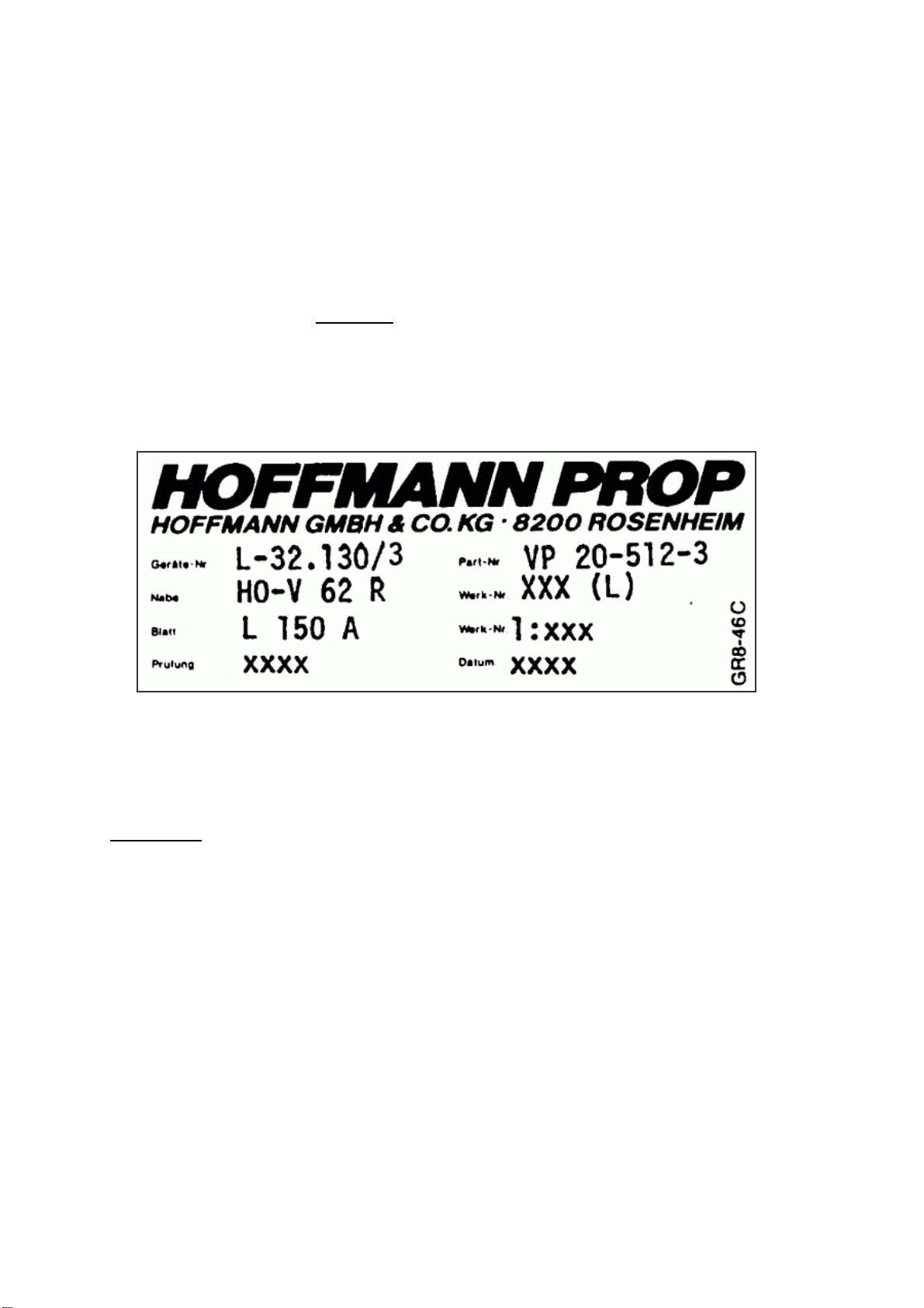
2- DESIGNATION ................................................................................................ 2-1
2-1. Designation of the Hub .............................................................................................2-1
2-2. Designation of the Blade...........................................................................................2-2
3- DESIGN DATA................................................................................................. 3-1
4- CONSTRUCTION............................................................................................. 4-1
4-1. Hub Assembly............................................................................................................4-1
4-2. Pitch Change Mechanism.........................................................................................4-1
4-2.1. HO – V62R..........................................................................................................4-1
4-2.2. HO – V62 ............................................................................................................4-5
4-3. Blade Assembly..........................................................................................................4-5
4-4. Blade Bearing.............................................................................................................4-6
4-5. Spinner Assembly......................................................................................................4-6
4-6. Counterweights..........................................................................................................4-6
5- OPERATION.................................................................................................... 5-1
5-1. Propeller Model HO – V62R....................................................................................5-2
6- INSTALLATION............................................................................................... 6-1
7- INSPECTION ................................................................................................... 7-1
7-1. Daily Inspection.........................................................................................................7-1
7-2. 100h Inspection..........................................................................................................7-2
7-3. Inspection of the blades.............................................................................................7-3
7-4. Damaged fibre glass cover........................................................................................7-6
7-5. Additional periodic inspections................................................................................7-6
61-10-01 ii
7-6. Overhaul.....................................................................................................................7-6
New Edition August 2003

Hoffmann Propeller
Manual No. E 0107.72A
7-7. Special inspections.....................................................................................................7-7
8- PROPELLER ADJUSTMENT.......................................................................... 8-1
9- MAINTENANCE AND REPAIR........................................................................ 9-1
10- SHIPPING AND STORAGE ....................................................................... 10-1
10-1. Shipping................................................................................................................10-1
10-2. Storage..................................................................................................................10-1
61-10-01 iii
New Edition August 2003

Hoffmann Propeller
Manual No. E 0107.72A
List of Illustrations
Fig. 4-1 Blade in "Take Off" Position..................................................................................4-3
Fig. 4-2 Blade in "Cruise" Position.....................................................................................4-4
Fig. 4-3 Blade in "Feathered" Position.................................................................................4-4
Fig. 4-4 Blade Tipping Type A + B.....................................................................................4-5
Fig. 7-1 Normal Erosion......................................................................................................7-3
Fig. 7-2 Blade root NO cracks in the silicone.....................................................................7-3
Fig. 7-3 Erosion tipping Type A .........................................................................................7-4
Fig. 7-4 Erosion tipping Type B.........................................................................................7-4
Fig. 7-5 Fine cracks in the paint or the tipping ...................................................................7-5
Fig. 7-6 Cracks in the paint of blade...................................................................................7-5
Fig. 7-7 Hair cracks in the paint...........................................................................................7-6
Fig. 9-1 Rework Leading Edge Type B ...............................................................................9-2
Fig. 9-2 Paint damage behind Blade Tipping B..................................................................9-2
Fig. 10-1 Propeller HO - V62.............................................................................................10-2
Fig. 10-2 Propeller HO - V62R.........................................................................................10-3
61-10-01 iv
New Edition August 2003

Hoffmann Propeller
Manual No. E 0107.72A
1- General
The propeller HO-V 62 () is a two bladed lightweight propeller with mechanical pitch
change device. It is equipped with a “Take Off Position” and a “Feathering Position”.
It was mainly designed and developed for the use with early generation of powered
gliders.
The propeller HO-V 62 R () is a two bladed lightweight propeller with mechanical
pitch change device. It is equipped with a “Take Off”-, a “Cruise”- and a “Feathering
Position”. It was mainly designed and developed for the use with the second
generation of powered gliders. The additional cruise position improves the flight
cruise performance of the powered glider considerable
The pitch change from the take off- to the cruising position can only be done with the
engine running. The change back from the cruising- to the take off position can be
done either with the engine running or the engine stopped.
The pitch change to the feathering position on both propellers has to be done with
the engine stopped or wind milling.
The tendency of the propeller blades of both propellers is always to return to the take
off position regardless whether the engine is running or stopped.
The propeller blades always return to the take off position if the feathering position
will fail.
In order to get the best propeller efficiency the correct blade angle adjustment is very
important, especially if the propeller blades L160BT are installed. Therefore the
instructions given by the aircraft manufacturer regarding the static RPM setting have
to be followed carefully. A higher static RPM will not automatically give better take off
and climb performance.
61-11-02 Page 1-1
New Edition August 2003

Hoffmann Propeller
Manual No. E 0107.72A
2- Designation
2-1. Designation of the Hub
HO- V 6 2 () () R () / Blade Model
1 2 3 4 5 6 7 8
1. Hoffmann GmbH & Co. KG
2. Variable pitch propeller
3. Number of basic model
4. Number of blades
5. Flange type: Blank = basic model
6. Number of hub extension from blade axis to
flange, if required blank: 104 mm (4.09 inch)
7. Propeller pitch
Blank: Mechanical two position propeller
R: Additional mechanical cruise position
A: Automatic pitch change system
H: Hydro mechanical pitch change
mechanism
HS: Hydro mechanical pitch change
mechanism with feathering position
8. Minor change not affecting airworthiness /
interchangeability
61-10-01 Page2-1
New Edition April 2004

Hoffmann Propeller
Manual No. E 0107.72A
2-2. Designation of the Blade
() () 160 BT -() () () ±()
9 10 11 12 13 14 15 16
9. Sense of rotation:
blank: right hand, tractor
D: right-hand, pusher
L: left-hand, tractor
LD: left-hand, pusher
10. blank: Type “A” or “ B “ erosion shield
C: Type “ C “ erosion shield
11. Basic diameter in cm
12. Designation of blade design
13. Designation of blade twist
14. B: electrical de-icing
15. Material of blade
Blank: compreg scarfed with lighter
wood
P: compreg
16. Decrease (-) or increase (+) of basic
diameter in cm
Blade Model (example only)
61-10-01 Page2-2
New Edition April 2004

Hoffmann Propeller
Manual No. E 0107.72A
The model designation, the serial-No. and the date and number of the inspection are
written on a decal on each blade shank. The serial-No. of the blade is also stamped
into the blade butt face (not visible from outside) and the retaining ring.
The complete designation of a variable pitch propeller is a combination of the
designation of the hub assembly and the blade assembly. Both designations are
separated by a slash mark.
Example: HO-V 62 R / L 160 BT
The serial-No. of the hub is also the serial-No. of the propeller assembly
Translation
Geräte- Nr.: TCDS-No.: Part- Nr.: Part-No.:
Nabe: Hub: Werk- Nr.: Serial-No.:
Blatt: Blade: Werk- Nr.: Serial-No.
Prüfung: Inspection: Datum: Date:
61-10-01 Page2-3
New Edition April 2004

Hoffmann Propeller
Manual No. E 0107.72A
3- Design data
Following data are only standard values and for information only. For installation
purposes only the data given in the applicable Type Certificate Data Sheet
(TCDS) No. 32.130 / 13 (latest edition) of the German Luftfahrt-Bundesamt
(LBA) are valid.
P max 75 kW (dependent on propeller diameter and
rpm)
n max 3600 1/min (dependent on diameter and
power)
Number of blades: 2
Diameter max: 170 cm
Pitch change range: about 75 deg
Weight: HO-V62 (Ø 170 cm)
HO-V62R (Ø 170 cm) about 9.0 kg (20 lbs)
about 10.0 kg (22.0 lbs)
Weight of the spinner: about 1.0 kg (2.2 lbs)
Polar moment of inertia: about 0.5 kgm2
Mounting flange: 80 mm diameter bolt circle,
6 studs 7/16 - 20 UNF,
center bore 47 mm diameter
61-10-01 Page3-1
New Edition April 2004

Hoffmann Propeller
Manual No. E 0107.72A
4- Construction
The HOFFMANN mechanical variable pitch propeller consists of 4 sub
assemblies:
- Hub assembly
- Blade assembly
- Spinner assembly
- Counterweight assembly if applicable
4-1. Hub Assembly
The hub is made of aluminium alloy, shot peened and anodised. It contains
the inner and the outer pitch change mechanism. At the mounting flange of the
propeller there are six (6) 7/16”- 20 UNF studs installed. The propeller is
mounted to the engine flange using washers and self-locking nuts.
With the Sportavia Limbach engine SL 1700() equipped with an engine flange
for fixed pitch propellers the conversion flange VP20 - 483 has to be used.
4-2. Pitch Change Mechanism
NOTE
Parts of the pitch change mechanism located outside the hub will be called
“outside change mechanism” and the parts inside “inside change mechanism”.
The advantage of the mechanical pitch change mechanism of the propeller
HO-V62 () is there are no bearings running permanently with the propeller
rpm, but only during the short period of pitch change
4-2.1. HO – V62R
NOTE
Item reference is to Figure 4-1() unless otherwise noted
61-10-01 Page4-1
New Edition April 2004

Hoffmann Propeller
Manual No. E 0107.72A
In order to change the propeller pitch, the aircraft has to be equipped with an
aircraft installed pitch change actuating system. This system is installed on the
engine of the aircraft and connected to the actuating lever or a handle in the
cockpit.
CAUTION
To perform the next step the engine has to run.
Propeller RPM has to be 1800 to max. 1900 RPM
During the propeller pitch change the two ball bearings (4-1), mounted to the
lever (4-2), which is an aircraft part, contacts the thrust plate (4-3) of the
propeller. The force of the lever has to act against the force of the four springs
(4-4) and the natural centrifugal twisting moment of the propeller blades. The
yoke (4-6) including the stop (4-11) will be pushed away from the front side of
the hub (4-7).
The pitch change rod (4-8) is connected to the pitch change fork (4-9) of the
internal pitch change mechanism. The pitch change pins of the propeller
blades engage the pitch change blocks (4-10) in the fork (4-9), which changes
the pitch of the propeller blades.
The four installed springs (4-4), together with the natural centrifugal twisting
moment of the propeller blades, always tend to return the propeller blades to
the “Take Off“ (fine pitch) position.
Figure 4 shows the three possible propeller blade angle position:
(Fig.4-1) The propeller blade is in the “Take Off “ position (at the finest bade
angle). The stop is locked within the “Stop Plate” (4-12) and held in this
position by the four springs (4-4)
(Fig.4-2)The propeller blade is in the “Cruising” position. The stop (4-11) is
resting against the front stop plate (4-12). The stop is now further forward. A
movement of about 1.5mm equals about a 5° pitch change and a drop of the
propeller rpm (full power) of about 500 rpm.
The change from take off pitch (fine pitch) to cruise pitch (coarse pitch) has to
be performed only at a propeller rpm between 1800 rpm and max. 1900 rpm.
The stop plate (4-12) is held in the down position by a spring (4-13). This rpm
is necessary to get enough centrifugal force of the stop plate (4-12) to
overcome the force of the return spring (4-13).
61-10-01 Page4-2
New Edition April 2004

Hoffmann Propeller
Manual No. E 0107.72A
If the actuating lever or handle in the cockpit will be pulled between 1800- and
max. 1900 propeller rpm, the yoke (4-6) is lifted from the hub (4-7). The
centrifugal force of the stop plate (4-12) compresses the return spring (4-13)
and allows the stop plate (4-12) to move outward till the inside of the hole
touches the pitch change rod (4-8). This is the stop for the cruising position
(high pitch). The yoke (4-6) movement, during the pitch change, is about 2 mm
only.
To change back from the cruise position to the take off position, with the
engine running, the propeller rpm has to be reduced to 1500 rpm or less. Now
the force of the return spring (4-13) is higher than the centrifugal force of the
stop plate (4-12). A slight pull on the actuating lever or handle in the cockpit
releases the stop plate (4-12) and allows the propeller blades to move to the
take off (fine pitch) position.
(Fig.4-3)The propeller blades are in the “Feathered” position. The correct
feathering blade angle is determined by the length of the connecting cable
from the engine-mounted lever (4-2) to the actuating lever or handle in the
cockpit. To feather the propeller blades the engine has to be stopped or wind
milling. The actuating lever or handle in the cockpit has to be locked in order to
hold the propeller blades in the feathered position against the force of the
springs (4-4). The thrust plate (4-3) acts as a safety stop outside the hub. It
prevents the propeller blades from reaching a position from which the force of
the springs (4-4) will not be able to return the propeller blades to the take off
(fine pitch) position.
Fig. 4-1 Blade in "Take Off" Position
61-10-01 Page4-3
New Edition April 2004

Hoffmann Propeller
Manual No. E 0107.72A
Fig. 4-2 Blade in "Cruise" Position
Fig. 4-3 Blade in "Feathered" Position
61-10-01 Page4-4
New Edition April 2004

Hoffmann Propeller
Manual No. E 0107.72A
4-2.2. HO – V62
CAUTION
To perform the next step the engine has to be stopped or wind milling.
The internal and external pitch change mechanism is the same as with the
propeller HO-V62R. Since the propeller HO-V62 is equipped with a take off
(fine pitch) and a feathering position only, the stop plate (4-12) and the return
spring (4-13) are deleted. The stop (4-11) of the yoke (4-6) rests directly
against the front part of the hub (4-7). To change to the feathered position or
back to the take off position is the same as with the propeller HO-V62R. It can
be done only with the engine stopped or wind milling.
4-3. Blade Assembly
The HOFFMANN composite blade is a joint construction. The blade root is
made of highly compressed hardwood (compreg) and the blade part is made
of light wood (spruce). Blades may also be manufactured of compressed wood
only. Special lag screws connect the compressed wood of the blade to a metal
ferrule.
For erosion protection of the blade leading edge two different types of
Hoffmann proved leading edge protections could be used.
Type A is a brass metal strip soft soldered to a bronze fabric and glued to the
blade FRP cover.
Type B is a special aluminium strip glued directly to the wooden core of the
blade. This tipping is mainly used on ITP- propeller blades.
Fig. 4-4 Blade Tipping Type A + B
61-10-01 Page4-5
New Edition April 2004

Hoffmann Propeller
Manual No. E 0107.72A
The propeller blade is covered with fibre-reinforced epoxy (FRP). Fatigue
failures due to vibration are unlikely with such blades because the internal
damping of the material is considerably higher than that of duralumin.
Several layers of special polyurethane paint (PU- paint) are sprayed onto the
fibre reinforced epoxy covering and the erosion tipping, this assures a high
resistance to atmospheric conditions. This polyurethane paint shows also high
resistance against erosion and mechanical damage. Coloured paint is required
to protect the wood against UV-rays. The thrust side is painted dull black to
avoid reflection of sunlight. For safety reasons the tips are painted with a
different colour to make the transparent propeller disc visible when the
propeller is running.
4-4. Blade Bearing
An axial needle bearing absorbs the centrifugal force of the blade. The bearing
races are made of steel. The needle cage is split into two halves to allow
exchange of the cage without removing the blade ferrule.
The blade ferrules are made of aluminium alloy, which is shot-peened to
prevent fatigue cracks. The blades are installed into the hub by a retention ring
(blade nut), made of aluminium alloy. The torque of the retention ring adjusts
the necessary pre-load of the blade bearing. The blade retention rings are
sealed with silicone rubber to prevent penetration of moisture into the blade
bearings. The blade shaft is sealed with a lip seal.
4-5. Spinner Assembly
The spinner dome is one piece and made of aluminium alloy. It is screwed to
the spinner bulkhead with Philips screws. The spinner bulkhead is made of an
aluminium sheet and mounted to the hub by 4 screws. The spinner bulkhead
also holds parts of the outside pitch change mechanism.
4-6. Counterweights
The propeller models HO-V62R are equipped with counterweights. These
counter-weights are required to reduce the pitch change forces while changing
the pitch from take off to cruise position. The counterweights are fixed to the
blade ferrule by clamp screws.
61-10-01 Page4-6
New Edition April 2004

Hoffmann Propeller
Manual No. E 0107.72A
5- Operation
Propeller HO-V62 and HO-V62R
CAUTION
Follow closely the instruction given in the aircraft manual.
The instruction given in this manual is for information only.
WARNING
Make sure the distance between the ball bearings and the thrust-plate is always
at least 1mm with the propeller blades in the take off position.
WARNING
Before starting the engine secure the aircraft according the aircraft flight
manual.
CAUTION
Perform engine run-up on paved and clean surfaces only.
Engine and propeller manufacturers do not recommend high rpm during
ground operation for a long time because the engine can be overheated and
foreign objects can damage the propeller.
CAUTION
The change to feathering position has to be done only with engine stopped or
wind milling
Start engine according to the flight manual and warm it up (oil temperature in
the green). Perform the static run up check according to the aircraft flight
manual.
61-10-01 Page5-1
New Edition April 2004

Hoffmann Propeller
Manual No. E 0107.72A
5-1. Propeller Model HO – V62R
CAUTION
Before performing any adjustments to the propeller make sure the engine
develops its full power and the rpm indicator is correct.
Adjustments may be performed only by certified mechanics.
1. The mechanical pitch stops (take off, cruise and feathering position) have
been set at the factory to meet the aircraft / engine specifications.
2. Start engine, warm it up (oil temperature in the green), perform the static run
up check according to the aircraft flight manual
3. Adjust the propeller rpm with the throttle to 1800 or max. 1900 rpm. Pull the
actuating lever or handle in the cockpit for a short moment and release. The
movement of the yoke (4-6) has to be 2 mm only. Do not move the throttle.
The rpm drop of the propeller should be about 500 rpm.
4. To change back from cruising position (coarse pitch) to take off position (fine
pitch) reduces the propeller rpm to 1500 rpm or below. Pull the actuating lever
or handle in the cockpit for a short moment and release. Open the throttle full
and check the static rpm. The value from the beginning (step 5.5) should be
reached again.
5. Repeat this test at least three times. If there is no problems perform a test
flight following the procedures given in the aircraft flight manual.
6. After the test flight re-check the torque of the stop nuts. Do not loosen the
nuts; only apply the required torque-according table 6.5. Make all necessary
entries in the aircraft log book.
61-10-01 Page5-2
New Edition April 2004

Hoffmann Propeller
Manual No. E 0107.72A
6- Installation
Propeller HO-V62 and HO-V62R
WARNING
Before starting any work on the propeller follow the precaution given in the
flight manual.
CAUTION
Propeller installation is subject to an immediate inspection by a licensed
engineer
CAUTION
Follow closely the instructions given in the aircraft manual.
The instructions in this manual are for information only.
1. Clean the propeller and engine flange with solvent. Engine torque is mainly
transferred by friction; therefore the surfaces have to be smooth and clean.
2. Remove the spark plug from the number one cylinder (closest to the propeller
flange). Turn the engine by hand until the piston of the number one cylinder is
on its upper dead center.
CAUTION
Do not install an o-ring on the engine flange.
3. Slide the propeller carefully onto the engine flange with the propeller blades
vertical.
4. Slide the washers onto the bolts. Torque the stop nuts equally crosswise.
5. Torque values for dry threads:
HO-V62 7/16" -20 UNF 45 - 47 Nm (390 - 410 inlbs.)
HO-V62R 7/16" -20 UNF 45 - 47 Nm (390 – 410 inlbs.)
61-10-01 Page6-1
New Edition April 2004

Hoffmann Propeller
Manual No. E 0107.72A
CAUTION
Do not grease the outer pitch change mechanism.
Use grease only to prevent corrosion.
6. Apply a very thin layer of grease to the thrust plate along the track of the ball
bearings. Use Calypsol H442 or equivalent.
7. Check the track of the propeller blades on the trailing edge about 10 cm
inboard from the blade tip. Maximum permissible track is 3 mm.
8. Check the propeller pitch actuating mechanism of the aircraft. It must be
installed according to the instructions of the aircraft manufacturer.
9. Make sure the distance of the ball bearings to the thrust plate has to be always
at least 1 mm if the propeller blades are in the take off (fine pitch) position.
10.Cycle the propeller several times from the take off to the feathering position.
11.If no problems are encountered prepare the aircraft for an engine run up
according to the aircraft flight manual.
61-10-01 Page6-2
New Edition April 2004
This manual suits for next models
1
Table of contents