- 2 -
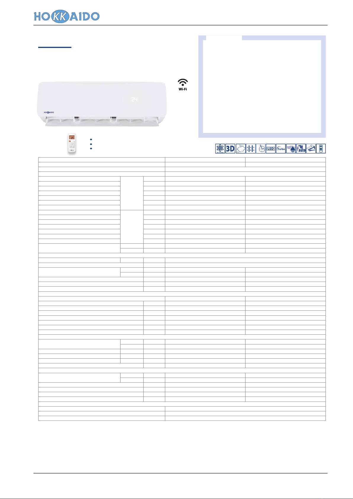
Series 4 Models: “Wall” Type Top Class R32 Refrigerant AC
TOP CLASS DC INVERTER
HKEU 264-354 ZAL
RESIDENTIAL R32
Wall
Models available in 2 power sizes 2.64 ~ 3.52 kW.
Seasonal energy efficiency class in cooling/heating
mode: A+++/A++ (2.64 kW); A++/A++ (3.52 kW).
SEER/SCOP values 8.5/4.6 (2.64 kW).
Operating range in cooling and heating: -15~43°C;
-30~30°C.
Extremely quiet: 21.5 dB(A) (2.64 kW);
22 dB(A) (3.52 kW).
Compact dimensions: only 189 mm deep.
Installation flexibility: up to 25 m splitting length and
10 m height difference between O.U. and I.U.
Possibility of access to tax deductions and to the
thermal account.
"3D" air diffusion
Photocatalytic filter
Position memorization function louvres
(optional)
Main features
Indoor unit model HKEU 264 ZAL HKEU 354 ZAL
Outdoor unit model HCNI 264 ZA HCNI 354 ZA
Type DC-Inverter heat pump
Control Remote control
Rated capacity (T=+35°C)
Cooling
kW 2.64 (0.91~4.40) 3.52 (0.93~4.75)
Rated absorbed power (T=+35°C) kW 0.60 (0.05~1.55) 0.98 (0.05~1.59)
Rated energy eciency coecient EER
3
4.40 3.59
Seasonal energy eciency class 626/2011
1
A+++ A++
Seasonal energy eciency index SEER
2
8.5 8.1
Annual energy consumption kWh/a 111 155
Theoretical load (Pdesignc) kW 2.7 3.5
Rated capacity (T=+7°C)
Heating
kW 2.86 (0.79~6.30) 3.81 (0.98~6.50)
Rated absorbed power (T=+7°C) kW 0.65 (0.14~2.10) 1.026 (0.17~2.13)
Rated energy performance coecient COP
3
4.42 3.71
Energy eciency class (average season) 626/2011
1
A++ A++
Seasonal energy eciency class index (average season) SCOP
2
4.6 4.6
Annual energy consumption kWh/a 792 852
Theoretical load (Pdesignh) kW 2.2 2.8
Operating limits (external temperature) Cooling °C -15~43 -15~43
Heating °C -30~30 -30~30
Electrical data
Power Outdoor unit Ph-V-Hz 1Ph - 220/240V - 50Hz
Power cable Type 3 x 2.5 mm
2
Absorbed current (rated) Cooling A 0.5~7.0 0.5~7.0
Heating A 1.0~9.2 1.2~9.4
Maximum current A 10 10
Maximum absorbed power kW 2.35 2.35
Connection wires between I.U. and O.U. no. 5 5
Refrigerant circuit
Refrigerant (GWP)
4
R32 (675) R32 (675)
Quantity refrigerant pre-load Kg 0.87 0.87
Tons of CO2 equivalent t 0.587 0.587
Diameter of refrigerant piping on liquid/gas mm (inches) ø6.35(1/4”) - ø9.52(3/8”) ø6.35(1/4”) - ø9.52(3/8”)
Max splitting length m 25 25
Max height dierence I.U. /O.U. m 10 10
Split length without additional charge m 5 5
Additional load g/m 12 12
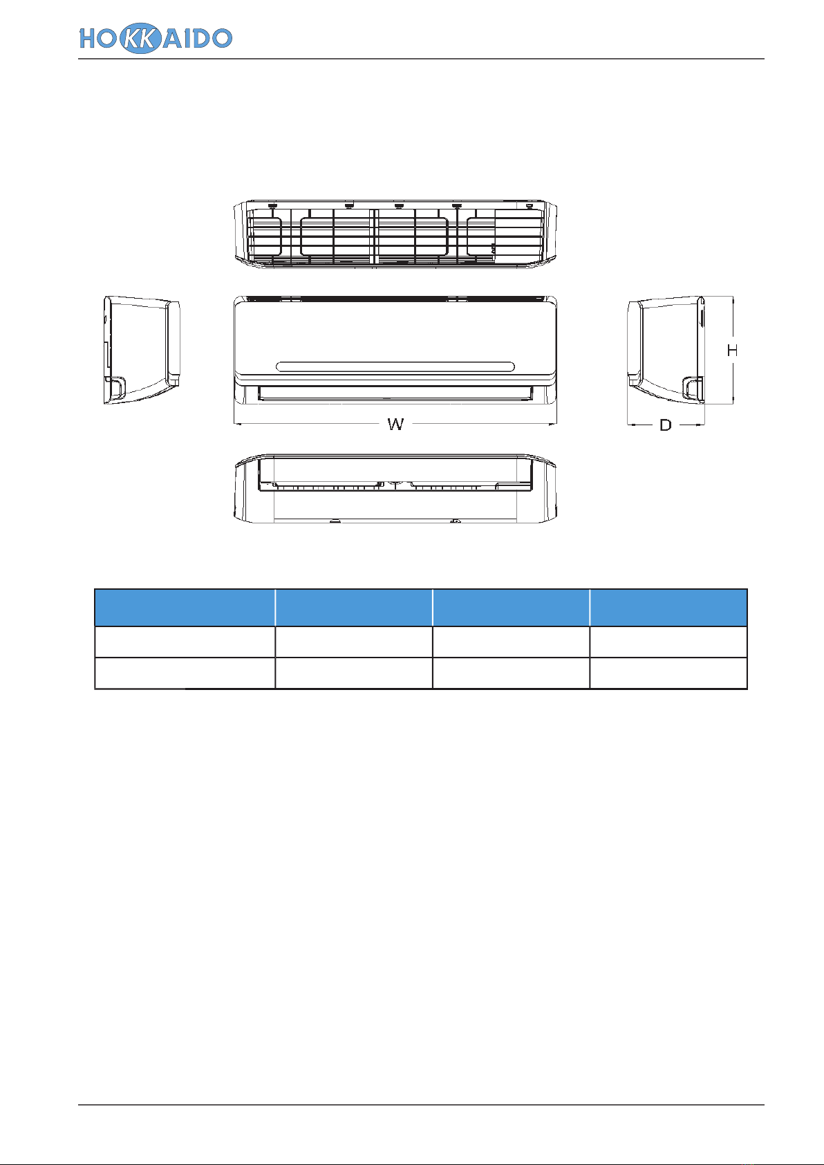
Indoor unit specications
Dimensions LxDxH mm 802x189x297 802x189x297
Net weight Kg 8.5 8.5
Sound pressure level (I.U.) Hi/Mi/Lo/ULo dB(A) 42/35/25/21.5 42/35/25/22
Sound power level (I.U.) Hi dB(A) 56 56
Handled air volume Hi/Mi/Lo m
3
/h 611/479/360 611/479/360
Motor power (Output) W 50 50
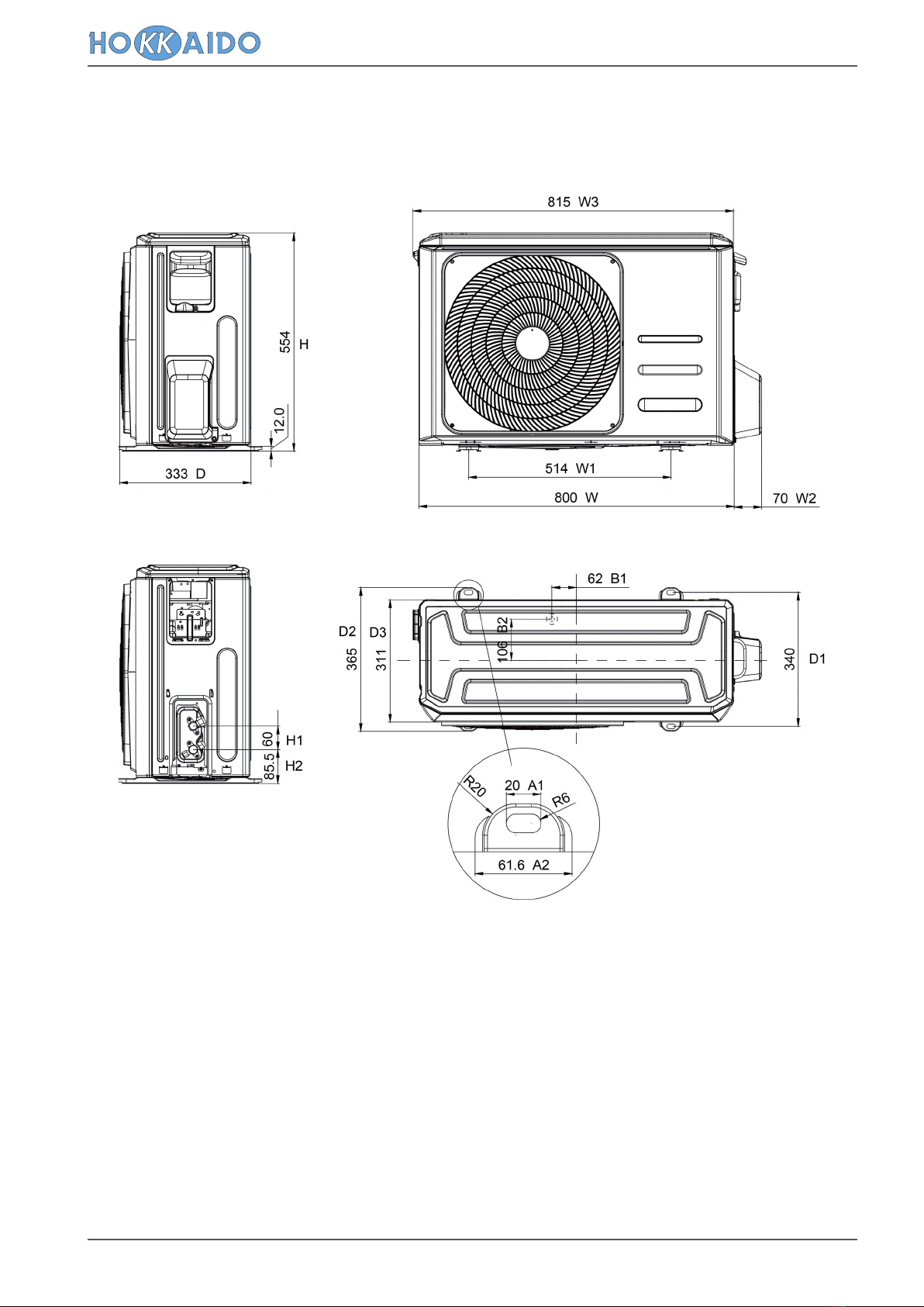
Specications of outdoor units
Dimensions LxDxH mm 800x333x554 800x333x554
Net weight Kg 34.7 34.7
Sound pressure level (O.U.) dB(A) 55.5 55.5
Sound power level (O.U.) dB(A) 64 65
Handled air (Max) m
3
/h 2000 2000
Motor power (Output) no. x W 40 40
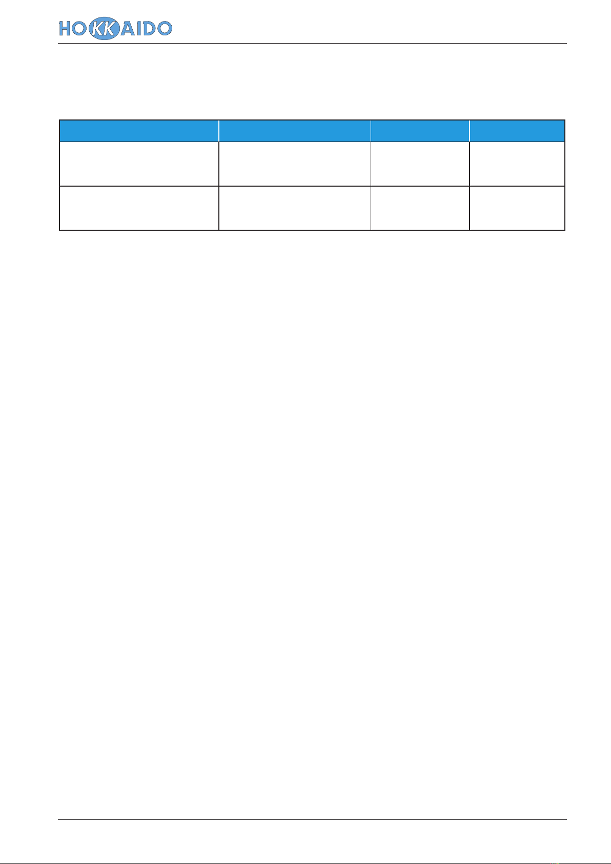
Optional parts
Wired remote control NO
Centralised control NO
Wi-Fi module KK-WIFI KIT
Infrared
remote
control
1 EU Delegated Regulation No.626/2011 on the new labelling indicating the energy consumption of air conditioners. 2 EU Regulation No.206/2012 - - Value measured according to harmonised standard EN14825. 3 Value measured according to
harmonised standard EN14511. 4 Refrigerant leakage contributes to climate change. When released into the atmosphere, refrigerants with a lower global warming potential (GWP) contribute less to global warming than those with a higher GWP.
This appliance contains a refrigerant with a GWP of 675. If 1 kg of this refrigerant fluid were released into the atmosphere, therefore, the impact on global warming would be 675 times higher than 1 kg of CO2, over a period of 100 years. Under no
circumstances should the user try to intervene on the refrigerant circuit or disassemble the product. Always contact qualified personnel if necessary.


 User manual")