HOLLAND LIFT HL-140 E12 User manual

Instruction manual
(translation of the original text)
Combistar Scissor lift
HL-140 E12 / N-120EL12
HL-160 E12 / N-140EL12
HL-190 E12 / N-165EL12
HL-220 E12 / N-195EL12

HL-140 E12 / HL-160 E12 / HL-190 E12 / HL-220 E12
N-120EL12 / N-140EL12 / N-165EL12 / N-195EL12
Rev. F
8/2/18 Page 2
© 2014, HOLLAND LIFT INTERNATIONAL B.V., Hoorn, The Netherlands.
No part of this publication may be copied and/or published by means of printing, photocopying, microfilm or any other way
whatsoever, without the prior written permission of HOLLAND LIFT INTERNATIONAL B.V.

HL-140 E12 / HL-160 E12 / HL-190 E12 / HL-220 E12
N-120EL12 / N-140EL12 / N-165EL12 / N-195EL12
Rev. F
Page 3 8/2/18
Contents Page
1 General information ................................................................................................................................ 6
1.1 Use of this instruction manual ..................................................................................................................6
1.1.1 Objective ..................................................................................................................................................6
1.1.2 Symbols used in this instruction manual ..................................................................................................6
1.2 Standard equipment.................................................................................................................................6
1.3 Additional documentation.........................................................................................................................6
1.4 Options.....................................................................................................................................................7
1.5 CE marking...............................................................................................................................................7
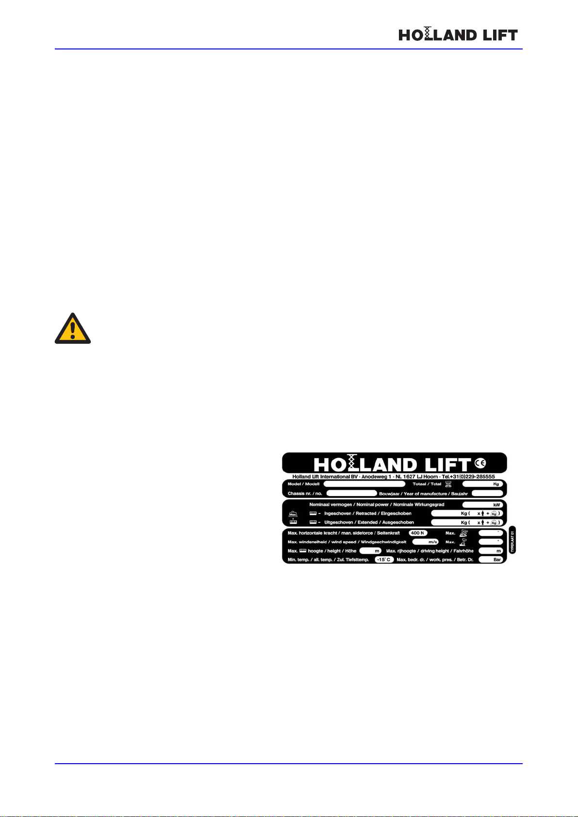
1.6 Scissor lift identification (type plate).........................................................................................................7
1.6.1 Location of the type plate.........................................................................................................................7
1.7 Terms of delivery and warranty................................................................................................................8
1.7.1 Terms of delivery......................................................................................................................................8
1.7.2 Warranty...................................................................................................................................................8
1.8 Intended use and modifications................................................................................................................8
1.8.1 Intended use.............................................................................................................................................8
1.8.2 Modifications ............................................................................................................................................8
1.9 Service and technical support ..................................................................................................................9
2 Safety.................................................................................................................................................... 10
2.1 Emergency procedures..........................................................................................................................10
2.1.1 Emergency stop .....................................................................................................................................10
2.1.2 Contact with high-voltage power lines....................................................................................................10
2.2 Safety instructions..................................................................................................................................10
2.2.1 General information................................................................................................................................10
2.2.2 Safety instructions during normal use ....................................................................................................11
2.2.3 Safety instructions during maintenance .................................................................................................12
2.2.4 Safety instructions when working on the electrical system ....................................................................12
2.2.5 Safety instructions when working on the hydraulic system....................................................................12
2.3 Liability ...................................................................................................................................................13
2.4 Users......................................................................................................................................................13
2.5 Intended use...........................................................................................................................................13
2.6 Decals on the scissor lift.........................................................................................................................14
2.6.1 Decals on the front.................................................................................................................................14
2.6.2 Decals on the left side............................................................................................................................15
2.6.3 Decals on the right side..........................................................................................................................16
2.6.4 Decal emergency descent protection.....................................................................................................17
2.6.5 Decals on the control box and on the platform.......................................................................................17
2.6.6 Decals in the left-side compartments .....................................................................................................19
2.7 Location of the safety provisions on the scissor lift ................................................................................20
2.7.1 Emergency stop button ..........................................................................................................................21
2.7.2 Dead man's switch .................................................................................................................................21
2.7.3 Safety prop.............................................................................................................................................21
2.7.4 Protective guardrail ................................................................................................................................21
2.7.5 Visual driving alarm/descent protection..................................................................................................21
2.7.6 Pipe/hose rupture safety device.............................................................................................................21
2.7.7 Emergency descent device...................................................................................................................22
2.7.8 Acoustic driving alarm/descent protection..............................................................................................22
2.7.9 Speed limiter ..........................................................................................................................................22
2.7.10 Tilt indicators..........................................................................................................................................23
2.7.11 Other safety provisions...........................................................................................................................23

HL-140 E12 / HL-160 E12 / HL-190 E12 / HL-220 E12
N-120EL12 / N-140EL12 / N-165EL12 / N-195EL12
Rev. F
8/2/18 Page 4
3 Controls................................................................................................................................................. 26
3.1 Overview ................................................................................................................................................26
3.2 The control box.......................................................................................................................................27
3.2.1 The control panel....................................................................................................................................28
3.3 Main switch.............................................................................................................................................29
4 Machine compartments......................................................................................................................... 30
4.1 Introduction.............................................................................................................................................30
4.2 Battery compartments............................................................................................................................30
4.3 Electrical box..........................................................................................................................................31
4.4 Hydraulic oil compartment......................................................................................................................32
4.5 Auxiliary switch raise/descend ...............................................................................................................33
4.6 Mains plug for battery charger................................................................................................................33
5 Normal use............................................................................................................................................ 34
5.1 Preparations before use.........................................................................................................................34
5.2 Starting...................................................................................................................................................34
5.3 Switching off...........................................................................................................................................36
5.4 Platform during transport........................................................................................................................36
5.5 Battery state-of-charge meter.................................................................................................................37
6 Transport............................................................................................................................................... 39
6.1 Towing....................................................................................................................................................39
6.1.1 Introduction.............................................................................................................................................39
6.1.2 Releasing the multiple disc brakes.........................................................................................................39
6.1.3 Point of special interest..........................................................................................................................40
6.2 Transport................................................................................................................................................40
6.2.1 Introduction.............................................................................................................................................40
6.2.2 Preparation.............................................................................................................................................41
6.2.3 Points of attention...................................................................................................................................41
7 Maintenance ......................................................................................................................................... 42
7.1 Maintenance overview............................................................................................................................42
7.1.1 Protective guardrail ................................................................................................................................43
7.2 Overviews...............................................................................................................................................44
7.2.1 Lubrication points...................................................................................................................................44
7.2.2 Tightening torques..................................................................................................................................45
7.3 Maintenance procedures........................................................................................................................45
7.3.1 Installing and removing the safety props................................................................................................45
7.3.2 Topping up the hydraulic system............................................................................................................46
7.3.3 Lubrication..............................................................................................................................................46
7.3.4 Check the tilt safety device.....................................................................................................................46
7.3.5 Inspecting the scissor mechanism .........................................................................................................47
8 Troubleshooting.................................................................................................................................... 48
9 Disposal................................................................................................................................................ 49
9.1 Introduction.............................................................................................................................................49
9.2 Disposal procedure ................................................................................................................................49
10 Technical specifications........................................................................................................................ 50
10.1 Technical specifications for HL-140 E12 / N-120EL12 ..........................................................................50
10.2 Technical specifications for HL-160 E12 / N-140EL12...........................................................................51
10.3 Technical specifications for HL-190 E12 / N-165EL12...........................................................................52
10.4 Technical specifications for HL-220 E12 / N-195EL12...........................................................................53

HL-140 E12 / HL-160 E12 / HL-190 E12 / HL-220 E12
N-120EL12 / N-140EL12 / N-165EL12 / N-195EL12
Rev. F
8/2/18 Page 6
1
General information
1.1 Use of this instruction manual
1.1.1 Objective
This instruction manual is intended for the users of the following scissor lifts:
HL-140 E12 / N-120EL12
HL-160 E12 / N-140EL12
HL-190 E12 / N-165EL12
HL-220 E12 / N-195EL12
1.1.2 Symbols used in this instruction manual
1.2 Standard equipment
Control box with a plug-in connection, which can be used on the platform and on the bottom
carriage.
Auxiliary switch for raising and lowering, on the electrical box.
Proportional drive.
Emergency descent device
Driving alarm.
Non-marking tyres
1.3 Additional documentation
Parts list.
Electrical and hydraulic diagram.
Scissor lift book (logbook).
Battery charger manual.
Documentation set for central grease lubrication system (option).
Comment
A comment gives additional information.
Note!
Failure to heed an instruction with this symbol and text may result in damage to the scissor
lift.
Warning
Failure to heed an instruction with this symbol and text may result in serious physical injury
or serious damage to the scissor lift.

HL-140 E12 / HL-160 E12 / HL-190 E12 / HL-220 E12
N-120EL12 / N-140EL12 / N-165EL12 / N-195EL12
Rev. F
Page 7 8/2/18
1.4 Options
AC 230 V connection on the platform.
Flashing beacons in addition to the acoustic driving alarm.
Ability to drive the scissor lift when fully extended.
Central grease lubrication system
U.K. specifications
1.5 CE marking
See the Declaration of Conformity.
1.6 Scissor lift identification (type plate)
The type plate contains information specific to the scissor lift.
1.6.1 Location of the type plate
The scissor lift's type plate is located behind the left-rear wheel.
The type plate contains the following information:
1. the manufacturer's name, address and telephone number
2. the model
3. the total weight (kg)
4. the chassis number
5. the year of construction
6. the nominal power (kW)
7. the maximum permissible weight on the platform when retracted (kg)
8. the maximum permissible weight on the platform when extended (kg)
Note!
Never remove the type plate.
Type plate

HL-140 E12 / HL-160 E12 / HL-190 E12 / HL-220 E12
N-120EL12 / N-140EL12 / N-165EL12 / N-195EL12
Rev. F
8/2/18 Page 8
9. the maximum horizontal force (N)
10. the maximum angle of inclination (°)
11. the maximum wind speed (m/s)
12. the maximum tilt (°)
13. the maximum height (m)
14. the maximum height when mobile
15. the minimum permissible temperature (°C)
16. the maximum operating pressure (bar)
1.7 Terms of delivery and warranty
1.7.1 Terms of delivery
All sales agreements with HOLLAND LIFT INTERNATIONAL B.V. are subject to the Metaalunie
terms and conditions.
1.7.2 Warranty
See the terms of delivery for the length of the warranty.
1.8 Intended use and modifications
1.8.1 Intended use
The scissor lift is only intended to be used to allow people to work at a height. The maximum load of
the platform (see type plate) must not be exceeded under any circumstances. Any other use is
contrary to the scissor lift's intended use. Only use the scissor lift in enclosed spaces with an
ambient temperature of between -15 °C and +40 °C.
1.8.2 Modifications
Modifications may only be made to the scissor lift after written permission has been obtained from
the management of HOLLAND LIFT INTERNATIONAL B.V.
The information contained in this instruction manual is based on the information regarding
constructions, material properties and work methods that was known to us at the time of publication.
We therefore reserve the right to make construction modifications. For this reason, HOLLAND LIFT
INTERNATIONAL B.V. also reserves the right to make alterations to the content of the instruction
manual without any prior notice.
Components may only be replaced by components provided by HOLLAND LIFT INTERNATIONAL
B.V. or components which can be considered to be of a comparable quality. HOLLAND LIFT
INTERNATIONAL B.V. reserves the right to decide whether these components are of a comparable
quality. The manufacturer can only be held liable if a written declaration stating that the components
are of comparable quality has been obtained from the manufacturer.

HL-140 E12 / HL-160 E12 / HL-190 E12 / HL-220 E12
N-120EL12 / N-140EL12 / N-165EL12 / N-195EL12
Rev. F
Page 9 8/2/18
1.9 Service and technical support
HOLLAND LIFT INTERNATIONAL B.V.
Anodeweg 1
1627 LJ Hoorn
The Netherlands
T+31 (0)229-285555
F+31 (0)229-285550
Wwww.hollandlift.com

HL-140 E12 / HL-160 E12 / HL-190 E12 / HL-220 E12
N-120EL12 / N-140EL12 / N-165EL12 / N-195EL12
Rev. F
8/2/18 Page 10
2
Safety
2.1 Emergency procedures
2.1.1 Emergency stop
To disable all of the scissor lift's functions:
Press the emergency stop button.
2.1.2 Contact with high-voltage power lines
Observe the following if the scissor lift comes into contact with high-voltage power lines:
1. Remain on the platform.
2. Drive the scissor lift out of the danger area.
3. Make sure bystanders do not touch the scissor lift.
4. Have the power disconnected from the high-voltage power lines.
5. Exit the scissor lift when the high-voltage power line is no longer energised.
2.2 Safety instructions
2.2.1 General information
Avoid any situation that may endanger the users of the scissor lift or any bystanders.
It is strictly forbidden:
• to lower hanging loads onto the scissor lift
• to use the scissor lift to hoist loads
• to attach advertising boards or banners to the scissor lift
• to increase the surface area of the platform
• to stand on the guardrails surrounding the platform
• to raise the height of the platform floor
• to use any type of ladder on the platform
• to enter or exit the platform in the raised position
• to tow the scissor lift on public roads
After every (major) repair, the scissor lift must be inspected and approved by an expert.
If any modifications or repairs are carried out which may affect the scissor lift's stability,
strength or performance, the scissor lift must be reinspected and approved by HOLLAND
LIFT INTERNATIONAL B.V.
Any inspections, tests, repairs or modifications must be recorded in the scissor lift logbook.
The weighted root mean square acceleration value (vibrations) that the user is subjected to
during use of the scissor lift is not greater than 2.5 m/s².

HL-140 E12 / HL-160 E12 / HL-190 E12 / HL-220 E12
N-120EL12 / N-140EL12 / N-165EL12 / N-195EL12
Rev. F
Page 11 8/2/18
The noise produced by the scissor lift in the work area at a distance of 7 metres and at
maximum load does not exceed 75 dB(A).
Exposure to the noise over a long period of time may be detrimental to the hearing if hearing
protection is not worn.
2.2.2 Safety instructions during normal use
Only use the scissor lift under the following conditions:
• there is no visible damage to the scissor lift
• all the functions work correctly
• all the safety devices work correctly
• the hydraulic system does not leak
• the hydraulic system contains the correct quantity of oil
Lock the covers of the cabinets on the bottom carriage.
Do not touch the moving or pivoting parts of the scissor lift (e.g. the scissor mechanism or the
steering gear).
Make sure the driving area and the work area are:
• sufficiently flat and able to support the weight of the scissor lift
• adequately lit
• free of obstacles
• free of snow and ice
Make sure the scissor lift cannot touch any fixed or moving obstacles.
Make sure no objects can fall from the platform (e.g. tools).
If tools which may cause a fire are used on the platform, a fire extinguisher must be present
on the platform.
The scissor lift may only be driven when fully extended if it is driven in an enclosed space on a
completely flat surface which is able to support the weight of the scissor lift. The user must be
aware of this. An additional safety requirement is that the scissor lift must be operated by two
people at all times. One person must work on the platform and the other person must remain
on the ground. They can maintain contact with each other using communication equipment.
In normal situations, the 8-metre stop should work. The key switch is in the ‘0’ position by
default. This means that it is possible to drive the scissor lift when it is extended up to a height
of 8 metres. Position ‘1’ means: it is possible to drive the scissor lift when it is extended to the
maximum height. The maximum speed is 0.5 km/h when the scissor lift is extended above a
height of 4 m.
The key switch is located on the electrical box.
Only charge the battery of the scissor lift in an area that is well ventilated and where smoking
and naked flame are prohibited.
Important conditions concerning driving up or down inclines in the scissor lift's longitudinal
direction:
• See the technical information in the instruction manual for the maximum incline that the
scissor lift can be driven on.
• The maximum load when driving up an incline is 80 kg (1 person).
• Place the platform in the lowest position.
• Select the slowest speed.
• Do not make any sharp steering movements when driving up an incline.
• Drive up an incline with the non-driven wheels uphill.

HL-140 E12 / HL-160 E12 / HL-190 E12 / HL-220 E12
N-120EL12 / N-140EL12 / N-165EL12 / N-195EL12
Rev. F
8/2/18 Page 12
It is strictly forbidden:
• to operate the scissor lift from the ground using the control box (except for transport
reasons or when carrying out maintenance work on the scissor lift)
• to use the scissor lift to carry out work on or near high-voltage electrical lines
• to use the scissor lift to work in an area where there is a risk of explosion
2.2.3 Safety instructions during maintenance
Always wear the required safety equipment (e.g. safety goggles, hearing protection, helmet)
when carrying out maintenance work on the scissor lift.
Prevent the scissor lift from being able to roll away. For example, place chocks against the
wheels.
Prevent the risk of crushing in the scissor mechanism. Make sure the safety prop has been
fitted before working on parts such as the scissor mechanism (e.g. lubricating the scissor
mechanism).
If the scissor lift is switched off during maintenance work and must remain off, take measures
to prevent the scissor lift from being switched on unexpectedly or unintentionally. Make sure
others cannot undo the measures that have been taken.
Before cleaning the scissor lift with steam, water or other liquids, protect all components that
must not be exposed to liquids. Remove the protection after cleaning the scissor lift.
Make sure oil, grease and other substances that are harmful to the environment are disposed
of in a safe and environmentally-friendly manner.
2.2.4 Safety instructions when working on the electrical system
Turn off the scissor lift before working on the electrical system.
2.2.5 Safety instructions when working on the hydraulic system
Make sure the correct fire extinguisher is available. Leaking oil can be hot and may therefore
cause a fire.
Lower the platform as far as possible before carrying out work on the hydraulic system.
Release the pressure before working on the hydraulic system.
Do not touch the hydraulic systems lines. Leaking, hot oil can cause burns or penetrate the
skin. If you come into contact with the oil, immediately contact a doctor who has experience
with this type of injury.

HL-140 E12 / HL-160 E12 / HL-190 E12 / HL-220 E12
N-120EL12 / N-140EL12 / N-165EL12 / N-195EL12
Rev. F
Page 13 8/2/18
2.3 Liability
HOLLAND LIFT INTERNATIONAL B.V. cannot be held liable for:
damage resulting from negligent use and/or maintenance of the scissor lift
any printing errors in the documentation or their consequences
2.4 Users
The management is obliged to instruct the users of the scissor lift in its use and maintenance
with the aid of the instruction manual, additional instructions and directions.
The instruction manual must be easily accessible to the user at all times in a tube that has
been fitted in the scissor lift's valve/electrical compartment for that purpose.
If necessary, HOLLAND LIFT INTERNATIONAL B.V. can provide a new copy on request.
The scissor lift may only be operated by people who are 18 years of age or older, who know
how to operate the scissor lift and who have read and understood the operating instructions
and regulations that are applicable to the HOLLAND LIFT INTERNATIONAL B.V. scissor lift.
It is strictly forbidden for people to operate the scissor lift when they are under the influence of
alcohol, drugs or medicine that impairs their ability to work safely.
In the Netherlands, it is recommended that operators be required to obtain the elevating work
platform safety certificate (Veiligheidscertificaat Hoogwerker). This is recognised by the
Vertical Transport Certification Supervisory Association (TCVT).
The IPAF Mobile Elevated Working Platform Operator course is recognised internationally.
Maintenance may only be carried out by people who have read and understood the
instructions contained in the instruction manual and who have specific knowledge of the
operation and construction of the scissor lift manufactured by HOLLAND LIFT
INTERNATIONAL B.V.
2.5 Intended use
Only use the scissor lift for the intended use.
Also see section 1.8.1.

HL-140 E12 / HL-160 E12 / HL-190 E12 / HL-220 E12
N-120EL12 / N-140EL12 / N-165EL12 / N-195EL12
Rev. F
8/2/18 Page 14
2.6 Decals on the scissor lift
2.6.1 Decals on the front
Front
1. Reflective film (on all corners)
2. Max. 2 persons + load
3. Crushing/pinching danger for hands
2
1
3

HL-140 E12 / HL-160 E12 / HL-190 E12 / HL-220 E12
N-120EL12 / N-140EL12 / N-165EL12 / N-195EL12
Rev. F
Page 15 8/2/18
2.6.2 Decals on the left side
Left side standard version
1. Scissor lift type indication
2. Presence in danger zone prohibited
3. Lubrication recommendations
4. Main switch icon
5. Main switch instructions
6. Only for enclosed spaces
7. Crushing/pinching danger for feet
8. Maintenance inspection
9. Safety prop instructions
10. Brand name
11. Reflective film (on all corners)

HL-140 E12 / HL-160 E12 / HL-190 E12 / HL-220 E12
N-120EL12 / N-140EL12 / N-165EL12 / N-195EL12
Rev. F
8/2/18 Page 16
2.6.3 Decals on the right side
Right side
1. Scissor lift type indication
2. Presence in danger zone prohibited
3. Check battery charge weekly
4. Instructions for preventing excessively low battery voltage
5. Reflective film (on all corners)
6. Only for enclosed spaces
7. Crushing/pinching danger for feet
8. Brand name
9. Safety prop instructions
10. Lubrication recommendations

HL-140 E12 / HL-160 E12 / HL-190 E12 / HL-220 E12
N-120EL12 / N-140EL12 / N-165EL12 / N-195EL12
Rev. F
Page 17 8/2/18
2.6.4 Decal emergency descent protection
Decal emergency descent protection
1. Decal emergency descent protection
2.6.5 Decals on the control box and on the platform
Decals on the inside of the platform

HL-140 E12 / HL-160 E12 / HL-190 E12 / HL-220 E12
N-120EL12 / N-140EL12 / N-165EL12 / N-195EL12
Rev. F
8/2/18 Page 18
230 VAC decal on the socket (option)
Descend with platform retracted
1. Concise operating instructions
2. ‘AC 230 V’ (option)
3. ‘Only lower the scissor lift with the platform retracted.’

HL-140 E12 / HL-160 E12 / HL-190 E12 / HL-220 E12
N-120EL12 / N-140EL12 / N-165EL12 / N-195EL12
Rev. F
Page 19 8/2/18
2.6.6 Decals in the left-side compartments
Decals in left-side compartment
1. ‘Filled with Equivis ZS32’
2. AC 230V

HL-140 E12 / HL-160 E12 / HL-190 E12 / HL-220 E12
N-120EL12 / N-140EL12 / N-165EL12 / N-195EL12
Rev. F
8/2/18 Page 20
2.7 Location of the safety provisions on the scissor lift
Location of the safety provisions on the scissor lift
1. Emergency stop button and dead man's switch on the control box
2. Protective guardrail
3. Visual driving alarm (optional)
4. Tilt protection
5. Safety prop
6. Pipe/hose rupture safety device
7. Emergency descent valve
8. Angle sensor
This manual suits for next models
7
Table of contents
Other HOLLAND LIFT Scissor Lift manuals
Popular Scissor Lift manuals by other brands

Terex
Terex Genie GS-1530 Operator's manual

Skyjack
Skyjack SJIII Series Maintenance & parts manual

Haulotte Group
Haulotte Group Compact 10DX Operator's manual

Major
Major MJ-TS6600 Installation, operation, and parts manual

LINCOS
LINCOS STD-3128 Use and maintenance manual

Draper
Draper SLX14 Installation & operating instructions

LINCOS
LINCOS U-B30 user manual

Terex
Terex Genie GS-2669RT Operator's manual

AMGO Hydraulics
AMGO Hydraulics LR06 Installation and service manual

Stratus
Stratus SAE-UT12000 Installation, operation & maintenance instructions

Ballymore
Ballymore SM0114113 Operator's manual

Genie
Genie Lift Tools GS-2669 Operator's manual