HOLLAND LIFT HL-190 D25 4WD/P/N User manual

User Manual
(translation of original version)
Combistar Scissor Lifts
HL-190 D25 4WD/P/N / B-165DL25 4WD/P/N
HL-220 D25 4WD/P/N / B-195DL25 4WD/P/N

HL-190 D25 4WD/P/N / HL-220 D25 4WD/P/N
B-165DL25 4WD/P/N / B-195DL25 4WD/P/N
Rev. A
Page 2 5/2/18
© 2011, HOLLAND LIFT INTERNATIONAL B.V., Hoorn, the Netherlands.
No part of this publication may be copied and/or published by means of printing, photocopying, microfilm or any other way
whatsoever, without the prior written permission of HOLLAND LIFT INTERNATIONAL B.V.

HL-190 D25 4WD/P/N / HL-220 D25 4WD/P/N
B-165DL25 4WD/P/N / B-195DL25 4WD/P/N
Rev. A
5/2/18 Page 3
Contents Page
1 General information ................................................................................................................................ 5
1.1 Use of this instruction manual ..................................................................................................................5
1.1.1 Objective ..................................................................................................................................................5
1.1.2 Symbols used in this instruction manual ..................................................................................................5
1.2 Standard equipment.................................................................................................................................5
1.3 Additional documentation.........................................................................................................................5
1.4 Optional extras .........................................................................................................................................5
1.5 CE marking...............................................................................................................................................6
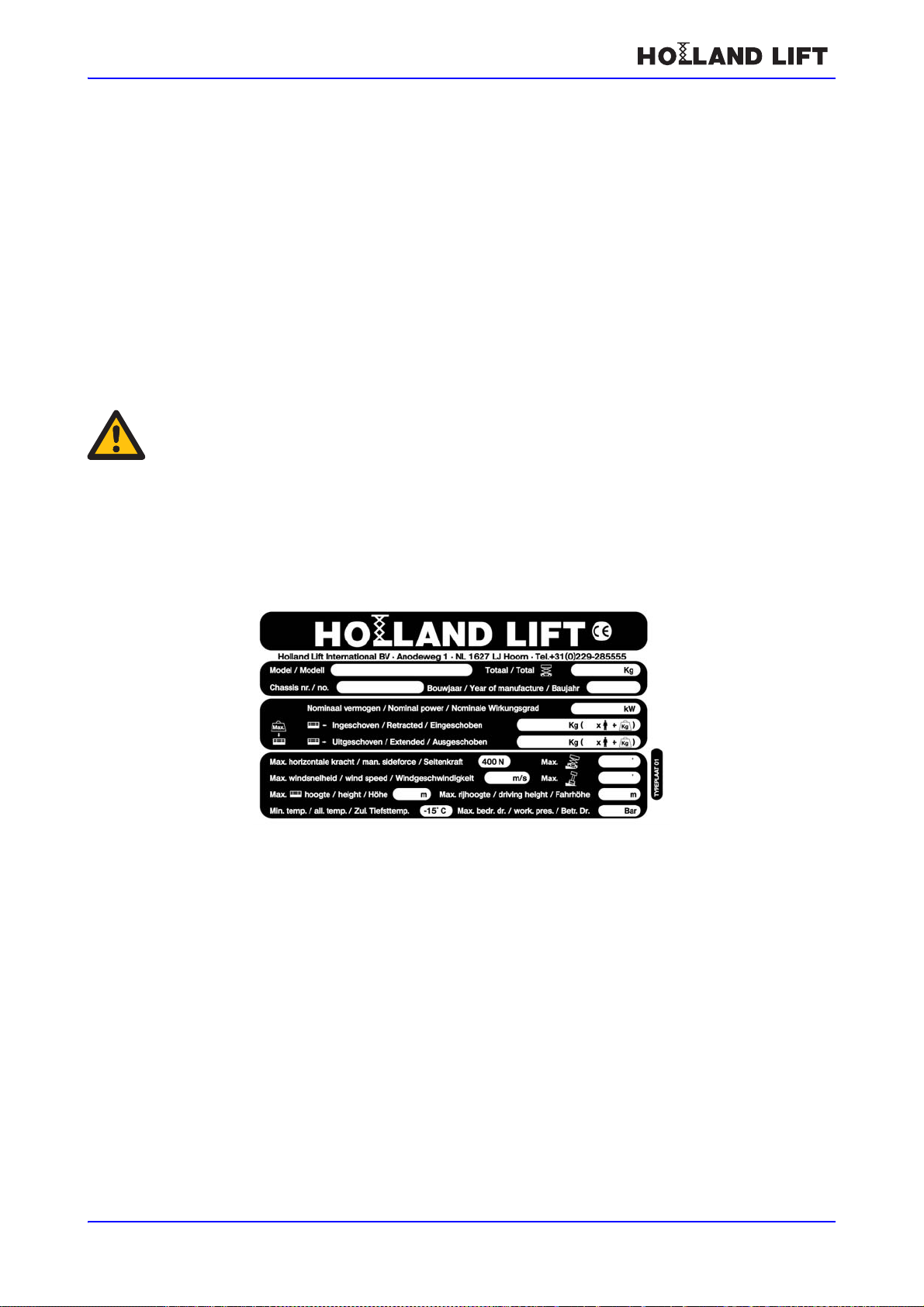
1.6 Scissor lift identification (type plate).........................................................................................................6
1.6.1 Location of the type plate.........................................................................................................................6
1.7 Delivery conditions and warranty .............................................................................................................7
1.7.1 Delivery conditions...................................................................................................................................7
1.7.2 Warranty...................................................................................................................................................7
1.8 Intended use and modifications................................................................................................................7
1.8.1 Intended use.............................................................................................................................................7
1.8.2 Modifications ............................................................................................................................................7
1.9 Service and technical support ..................................................................................................................8
2 Safety...................................................................................................................................................... 9
2.1 Emergency procedures............................................................................................................................9
2.1.1 Emergency stop .......................................................................................................................................9
2.1.2 Contact with electrical (high voltage) cables............................................................................................9
2.2 Safety instructions....................................................................................................................................9
2.2.1 General information..................................................................................................................................9
2.2.2 Safety instructions during normal use ....................................................................................................10
2.2.3 Safety regulations during maintenance..................................................................................................11
2.2.4 Safety regulations when working on the electrical system.....................................................................11
2.2.5 Safety regulations when working on the hydraulic system.....................................................................11
2.3 Liability ...................................................................................................................................................11
2.4 Users......................................................................................................................................................11
2.5 Intended use...........................................................................................................................................12
2.6 Stickers on the scissor lift.......................................................................................................................13
2.6.1 Stickers on the front of the scissor lift.....................................................................................................13
2.6.2 Stickers on the left-hand side of the scissor lift ......................................................................................14
2.6.3 Stickers on the right-hand side of the scissor lift....................................................................................15
2.6.4 Stickers on the platform..........................................................................................................................16
2.6.5 Stickers in the valve/electrical compartment. .........................................................................................17
2.6.6 Sticker on the engine..............................................................................................................................18
2.6.7 Sticker on the control box.......................................................................................................................18
2.7 Location of the safety devices on the scissor lift ....................................................................................19
2.7.1 Emergency stop button ..........................................................................................................................20
2.7.2 Safety bracket ........................................................................................................................................20
2.7.3 Protective scissor skirt............................................................................................................................20
2.7.4 Driving alarm - visual..............................................................................................................................20
2.7.5 Emergency descent device....................................................................................................................21
2.7.6 Driving alarm – acoustic.........................................................................................................................22
2.7.7 Speed limiter ..........................................................................................................................................22
2.7.8 Tilt indicator............................................................................................................................................22
2.7.9 Overload safety device...........................................................................................................................23
2.7.10 Lifting cylinder safety device ..................................................................................................................23
2.7.11 Pipe/hose break safety device ...............................................................................................................24

HL-190 D25 4WD/P/N / HL-220 D25 4WD/P/N
B-165DL25 4WD/P/N / B-195DL25 4WD/P/N
Rev. A
Page 4 5/2/18
3 Controls................................................................................................................................................. 25
3.1 Overview ................................................................................................................................................25
3.2 The control box.......................................................................................................................................26
3.2.1 The main control panel...........................................................................................................................27
3.2.2 Prop control panel..................................................................................................................................28
4 Valve and electrical compartment......................................................................................................... 29
4.1 Main switch.............................................................................................................................................29
4.2 Control box.............................................................................................................................................30
4.2.1 Control panel on the control box ............................................................................................................30
4.2.2 Fuses......................................................................................................................................................30
5 Engine compartment............................................................................................................................. 31
6 Normal use............................................................................................................................................ 32
6.1 Preparations before use.........................................................................................................................32
6.2 Starting...................................................................................................................................................32
6.3 Turning off ..............................................................................................................................................32
6.4 Sliding door safety device (optional) ......................................................................................................33
6.5 Platform during transport........................................................................................................................33
6.6 Oscillating axle.......................................................................................................................................33
6.7 Automatically levelling the prop cylinders...............................................................................................34
7 Transport............................................................................................................................................... 35
7.1 Towing....................................................................................................................................................35
7.1.1 Introduction.............................................................................................................................................35
7.1.2 Releasing the multiple disc brakes.........................................................................................................35
7.1.3 Points of attention...................................................................................................................................36
7.2 Transport................................................................................................................................................36
7.2.1 Introduction.............................................................................................................................................36
7.2.2 Preparation.............................................................................................................................................37
7.2.3 Points of attention...................................................................................................................................37
8 Maintenance ......................................................................................................................................... 38
8.1 Maintenance overview............................................................................................................................38
8.2 Overviews...............................................................................................................................................39
8.2.1 Protective scissor skirt............................................................................................................................39
8.2.2 Lubrication points...................................................................................................................................39
8.2.3 Tightening torques..................................................................................................................................41
8.3 Maintenance procedures........................................................................................................................41
8.3.1 Installing and removing the safety brackets ...........................................................................................41
8.3.2 Topping up the hydraulic system............................................................................................................42
8.3.3 Lubrication..............................................................................................................................................42
8.3.4 Check the tilt safety device.....................................................................................................................42
8.3.5 Inspecting the scissor mechanism .........................................................................................................42
9 Rectifying faults..................................................................................................................................... 44
10 Disposal................................................................................................................................................ 45
10.1 Introduction.............................................................................................................................................45
10.2 Disposal procedure ................................................................................................................................45
11 Technical specifications........................................................................................................................ 46
11.1 Technical specifications for HL-190 D25 4WD/P/N / B-165DL25 4WD/P/N...........................................46
11.2 Technical specifications for HL-220 D25 4WD/P/N / B-195DL25 4WD/P/N...........................................47
12 EC Declaration...................................................................................................................................... 48

HL-190 D25 4WD/P/N / HL-220 D25 4WD/P/N
B-165DL25 4WD/P/N / B-195DL25 4WD/P/N
Rev. A
5/2/18 Page 5
1
General information
1.1 Use of this instruction manual
1.1.1 Objective
This instruction manual is intended for the users of the following scissor lifts:
HL-190 D25 4WD/P/N / B-165DL25 4WD/P/N
HL-220 D25 4WD/P/N / B-195DL25 4WD/P/N
1.1.2 Symbols used in this instruction manual
1.2 Standard equipment
1. Control box with a plug-in connection, which can be used on the bottom carriage and on the
platform.
2. Auxilliary switch for raising and lowering in the valve/electrical compartment.
3. Proportional drive.
4. Unidirectional extendable platform.
1.3 Additional documentation
HATZdiesel engine documentation set.
Parts catalogue.
Electrical and hydraulic diagram.
Logbook.
1.4 Optional extras
230 V AC connection on the platform.
Flashing lights in addition to the acoustic driving alarm.
Sliding door on the side of the platform.
Possibility to drive the scissor lift when fully extended.
Easylubelubrication system (10 lubrication points).
Comment
A comment gives additional information.
Note!
If an instruction with this symbol and title is ignored, it may result in the scissor lift becoming
damaged.
Warning
If an instruction with this symbol and title is ignored, it may lead to serious physical injury or
serious damage to the scissor lift.

HL-190 D25 4WD/P/N / HL-220 D25 4WD/P/N
B-165DL25 4WD/P/N / B-195DL25 4WD/P/N
Rev. A
Page 6 5/2/18
Automatic lubrication system (78/90 lubrication points).
Generator.
Non-marking tyres.
1.5 CE marking
See the Declaration of Conformity.
1.6 Scissor lift identification (type plate)
The type plate contains information specific to the scissor lift.
1.6.1 Location of the type plate
The scissor lift’s type plate can be found on the bottom carriage.
The type plate contains the following information:
The manufacturer’s name, address and telephone number.
The model.
The total weight (kg).
The chassis number.
The year of construction.
The nominal power (kW).
The maximum permissible weight on the platform when retracted (kg).
The maximum permissible weight on the platform when extended (kg).
The maximum horizontal force (N).
The maximum angle of inclination ().
The maximum wind speed (m/s).
The maximum tilt ().
Note!
Never remove the type plate.
Type plate

HL-190 D25 4WD/P/N / HL-220 D25 4WD/P/N
B-165DL25 4WD/P/N / B-195DL25 4WD/P/N
Rev. A
5/2/18 Page 7
The maximum height (m).
The maximum height when mobile.
The minimum permissible temperature (° C).
The maximum operating pressure (bar).
1.7 Delivery conditions and warranty
1.7.1 Delivery conditions
HOLLAND LIFT INTERNATIONAL B.V. delivers products in accordance with the delivery and
payment conditions issued by the Metaalunie, dated 1st January 2008.
1.7.2 Warranty
For the warranty period, see the delivery conditions.
1.8 Intended use and modifications
1.8.1 Intended use
The scissor lift is only intended to be used to allow people to work at a height. The platform’s
maximum load (see type plate) must not be exceeded under any circumstances. Any other use is
contrary to the scissor lift’s intended use.
1.8.2 Modifications
Modifications to the scissor may only be made lift after written permission has been given by the
management of HOLLAND LIFT INTERNATIONAL B.V.
The information contained in this instruction manual is based on information regarding
constructions, material properties and work methods known by us at the time of publication. We,
therefore, reserve the right to make construction alterations. For this reason, HOLLAND LIFT
INTERNATIONAL B.V. also reserves the right to make alterations to the content of the instruction
manual without the need to give prior notification.
Components may only be replaced by components provided by HOLLAND LIFT INTERNATIONAL
B.V. or components which can be considered to be of an equal quality. HOLLAND LIFT
INTERNATIONAL B.V. reserves the right to decide whether these components are of an equal
quality. The manufacturer can only be held liable if a written declaration stating that the components
are of an equal quality has been received from the manufacturer.

HL-190 D25 4WD/P/N / HL-220 D25 4WD/P/N
B-165DL25 4WD/P/N / B-195DL25 4WD/P/N
Rev. A
5/2/18 Page 8
1.9 Service and technical support
HOLLAND LIFT INTERNATIONAL B.V.
Anodeweg 1
1627 LJ Hoorn
The Netherlands
T+31 (0)229-285555
F+31 (0)229-285550
Wwww.hollandlift.com

HL-190 D25 4WD/P/N / HL-220 D25 4WD/P/N
B-165DL25 4WD/P/N / B-195DL25 4WD/P/N
Rev. A
5/2/18 Page 9
2
Safety
2.1 Emergency procedures
2.1.1 Emergency stop
To disable all of the scissor lift’s functions:
Press the emergency stop button.
2.1.2 Contact with electrical (high voltage) cables
If the scissor lift comes into contact with electrical (high voltage) cables:
1. Remain on the platform.
2. Move the scissor lift out of the danger area.
3. Make sure bystanders do not touch the scissor lift.
4. Disconnect the electrical (high voltage) cables.
5. Only exit the scissor lift after the electrical (high voltage) cables have been disconnected.
2.2 Safety instructions
2.2.1 General information
Avoid any situation that may endanger the users of the scissor lift or any bystanders.
It is strictly forbidden to:
• Attach overhanging loads to the scissor lift.
• Attach advertising boards or banners to the scissor lift.
• Increase the working platform’s surface area.
• Stand on the platform’s railings.
• Raise the height of the platform’s floor.
• Tow the scissor lift on public roads.
After every (large) repair, the scissor lift must be inspected and approved by an expert.
If any modifications or repairs are carried out which may affect the scissor lift's stability,
strength or performance, the scissor lift must be reinspected and approved by HOLLAND
LIFT INTERNATIONAL B.V..
Any inspections, tests, repairs or alterations must be recorded in the scissor lift’s logbook.
The weighted root mean square acceleration value (vibrations) that the user is subjected to
during use of the scissor lift is not greater than 2.5 m/s2.
The airborne noise produced by the scissor lift in the work area at a distance of 7 metres and
at a maximum load is not greater than 87 dB(A).
Exposure to the airborne noise over a long period of time may have a harmful effect on the
ears if ear protection is not worn.

HL-190 D25 4WD/P/N / HL-220 D25 4WD/P/N
B-165DL25 4WD/P/N / B-195DL25 4WD/P/N
Rev. A
5/2/18 Page 10
2.2.2 Safety instructions during normal use
Only use the scissor lift under the following conditions:
• There is no visible damage to the scissor lift.
• All the functions work.
• All the safety devices work.
• The hydraulic system does not leak.
• The hydraulic system has the correct quantity of oil.
Lock the covers of the boxes on the bottom carriage.
Do not touch the scissor lift's moving parts or hinged components (e.g. the scissor
mechanism or the steering gear).
Make sure the driving area and the work area are:
• Sufficiently flat and able to take the weight of the scissor lift.
• Sufficiently lit.
• Free of obstacles.
• Free of snow and ice.
Make sure the scissor lift cannot touch any fixed or moving obstacles.
Make sure no objects can fall from the platform (e.g. tools).
If tools which may cause a fire are used on the platform, then there must be a fire extinguisher
on the platform.
The scissor lift may only be driven when fully extended (16.7/19.7 m) if it is driven on a flat
surface which is able to take the weight of the scissor lift. The user must be aware of this
before using the scissor lift. As an extra safety requirement, the scissor lift must always be
used by two people, where one person is on the platform and one person remains on the
ground. They must have a suitable means of communication. In the standard situation, the
8-metre cut-off must be set using the key switch. Position “0” is the setting where the scissor
lift can be driven when at a height of 8 meters and “1” is the setting where the scissor lift can
be driven at a height of 16.7/19.7 meters. The speed will not be greater than 0.5 km/h.
The key switch is located on the electrical box.
Only charge the scissor lift’s battery in an area that is well ventilated and where a naked flame
and smoking are forbidden.
Important conditions concerning driving up or down inclines in the scissor lift’s longitudinal
direction:
• See the technical information in the instruction manual for the maximum inclination.
• The maximum load when driving up an incline is 80 kg (1 person).
• Place the platform in the lowest position.
• Select the slowest speed.
• Do not make any sharp steering movements when driving up an incline.
• Do not drive up an incline with the non-driven wheels.
It is strictly forbidden to:
• Operate the scissor lift from the ground using the control panel (except for transport
reasons or carrying out maintenance on the scissor lift).
• Use the scissor lift to carry out work on or near electrical (high voltage) cables.
• Use the scissor lift to work in an area where there is a risk of an explosion.

HL-190 D25 4WD/P/N / HL-220 D25 4WD/P/N
B-165DL25 4WD/P/N / B-195DL25 4WD/P/N
Rev. A
5/2/18 Page 11
2.2.3 Safety regulations during maintenance
Always wear the required safety equipment (e.g. safety goggles, ear protection, helmet) when
carrying out maintenance work on the scissor lift.
Prevent the scissor lift from being able to roll away. For example, place chocks against the
wheels.
Prevent the risk of becoming trapped in the scissor mechanism. Make sure the safety
brackets have been fitted before working, for example, on the scissor mechanism (e.g.
lubricating the scissor mechanism).
If the scissor lift was turned off during maintenance work and must remain turned off, take
measures to prevent the scissor lift from unexpectedly or unintentionally being turned on.
Make sure others cannot undo the measures that have been taken.
Before cleaning the scissor lift with steam, water or other liquids, protect all the components
that must not be exposed to liquids. Remove the protection after cleaning the scissor lift.
Make sure oil, grease and other substances that are harmful to the environment are disposed
of in a safe and environmentally-friendly manner.
2.2.4 Safety regulations when working on the electrical system
Turn off the scissor lift before working on the electrical system.
2.2.5 Safety regulations when working on the hydraulic system
Make sure the correct fire extinguisher is available. Leaking oil can be hot and cause a fire.
Lower the platform as far as possible before carrying out work on the hydraulic system.
Remove the pressure before working on the hydraulic system.
Do not touch the hydraulic system’s lines. Leaking, hot oil can cause burns or penetrate the
skin. If you come into contact with oil, immediately see a doctor who has experience with this
type of wound.
2.3 Liability
HOLLAND LIFT INTERNATIONAL B.V. cannot be held liable for:
Damage resulting from negligent use and/or maintenance of the scissor lift.
Any printing errors in the documentation or their consequences.
2.4 Users
The management is obliged to instruct the users of the scissor lift in its use and maintenance
with the aid of the instruction manual, additional instructions and directions.
The instruction manual must be easily accessible to the user at all times in a tube that has
been fitted in the scissor lift’s valve/electrical box for that purpose. If necessary, HOLLAND
LIFT INTERNATIONAL B.V. can provide a new copy of the instruction manual on request.
The scissor lift may only be operated by people who are 18 years of age or older and who
have read and understood the operating instructions and regulations that are applicable to the
HOLLAND LIFT INTERNATIONAL B.V. scissor lift.

HL-190 D25 4WD/P/N / HL-220 D25 4WD/P/N
B-165DL25 4WD/P/N / B-195DL25 4WD/P/N
Rev. A
5/2/18 Page 12
It is strictly forbidden for people operate the scissor lift when they are under the influence of
alcohol, drugs or medicine that makes them drowsy.
In the Netherlands: Operators are recommended to have the “Veiligheidscertificaat
Hoogwerker”. This is recognized by the Stichting Toezicht Certificatie Verticaal Transport
(TCVT).
The IPAF mobile elevated working platforms operator course is recognized internationally.
Maintenance may only be carried out by people who have read and understood the
instructions contained in the instruction manual and who have specific knowledge of the
operation and construction of the scissor lift manufactured by HOLLAND LIFT
INTERNATIONAL B.V..
2.5 Intended use
Only use the scissor lift for the intended use.

HL-190 D25 4WD/P/N / HL-220 D25 4WD/P/N
B-165DL25 4WD/P/N / B-195DL25 4WD/P/N
Rev. A
5/2/18 Page 13
2.6 Stickers on the scissor lift
2.6.1 Stickers on the front of the scissor lift
1. Reflective material (on all the corners).
2. Max. 2 persons + load.
3. Risk of hands becoming trapped.
4. Emergency descent procedure.
5. Anti-slip material.
Front

HL-190 D25 4WD/P/N / HL-220 D25 4WD/P/N
B-165DL25 4WD/P/N / B-195DL25 4WD/P/N
Rev. A
5/2/18 Page 14
2.6.2 Stickers on the left-hand side of the scissor lift
1. Scissor lift type number.
2. Brand name.
3. Sticker for the safety bracket.
4. Fire risk. Diesel.
5. Engine maintenance instructions.
6. Shell Tellus 32.
7. Hydraulic oil
8. Not permitted to be in the danger zone.
9. Inspection sticker.
10. Lubrication advice.
11. Reflective material (on all the corners).
Left-hand side

HL-190 D25 4WD/P/N / HL-220 D25 4WD/P/N
B-165DL25 4WD/P/N / B-195DL25 4WD/P/N
Rev. A
5/2/18 Page 15
2.6.3 Stickers on the right-hand side of the scissor lift
1. Brand name.
2. Scissor lift type number.
3. Safety bracket.
4. Main switch.
5. Main switch symbol.
6. Not permitted to be in the danger zone.
7. 230 V AC (optional).
8. Lubrication advice.
9. Reflective material (on all the corners).
Right-hand side

HL-190 D25 4WD/P/N / HL-220 D25 4WD/P/N
B-165DL25 4WD/P/N / B-195DL25 4WD/P/N
Rev. A
5/2/18 Page 16
2.6.4 Stickers on the platform
1. Concise operating instructions.
Sticker on the 230 V AC switch box (optional).
Stickers on the inside of the platform

HL-190 D25 4WD/P/N / HL-220 D25 4WD/P/N
B-165DL25 4WD/P/N / B-195DL25 4WD/P/N
Rev. A
5/2/18 Page 17
2.6.5 Stickers in the valve/electrical compartment.
1. Extendable platform emergency procedure.
2. Battery pole location.
Sticker on the 230 V AC socket (optional).
Valve / electrical compartment

HL-190 D25 4WD/P/N / HL-220 D25 4WD/P/N
B-165DL25 4WD/P/N / B-195DL25 4WD/P/N
Rev. A
5/2/18 Page 18
2.6.6 Sticker on the engine
This sticker uses pictures to explain the maintenance instructions for the diesel engine.
2.6.7 Sticker on the control box
1. Only lower the scissor lift when the platform has been retracted.
Diesel engine maintenance instructions
The control box

HL-190 D25 4WD/P/N / HL-220 D25 4WD/P/N
B-165DL25 4WD/P/N / B-195DL25 4WD/P/N
Rev. A
5/2/18 Page 19
2.7 Location of the safety devices on the scissor lift
1. Emergency stop button
2. Driving alarm - acoustic
3. Driving alarm – visual (optional extral)
4. Limit switch – 4/8 metres
5. Tilt indicator
6. Proximity switch – lifting cylinder
7. Emergency descent valve
8. Pipe/hose break safety device
9. Safety bracket (both sides)
10. Protective scissor skirt
11. Controlled one-way valves in prop cylinders
12. Oscillating axle lock
13. Sliding door switch
Safety devices
12
2
5
10
9
4/6
7/8
3
11
1
13

HL-190 D25 4WD/P/N / HL-220 D25 4WD/P/N
B-165DL25 4WD/P/N / B-195DL25 4WD/P/N
Rev. A
5/2/18 Page 20
2.7.1 Emergency stop button
The emergency stop button can be used to turn off all of the scissor lift’s functions.
All of the functions stop when the emergency stop button is pressed.
If the emergency stop button is pulled out and rotated a quarter of a revolution, then all the
functions will be turned back on after 2 seconds.
2.7.2 Safety bracket
The safety brackets prevent people from becoming trapped in the scissor mechanism when work
must be carried out on it.
2.7.3 Protective scissor skirt
The protective scissor skirt prevents people from coming into contact with the scissor mechanism's
moving parts.
2.7.4 Driving alarm - visual
The visual driving alarm is activated when the scissor lift is being driven: two lights will flash when it
is being driven.
Emergency stop button
Comment
Only for scissor lifts with the “visual driving alarm” option.
E
M
E
R
G
E
N
C
Y
S
T
O
P
This manual suits for next models
3
Table of contents
Other HOLLAND LIFT Scissor Lift manuals
Popular Scissor Lift manuals by other brands

Terex
Terex Genie GS-1530 Operator's manual

Skyjack
Skyjack SJIII Series Maintenance & parts manual

Haulotte Group
Haulotte Group Compact 10DX Operator's manual

Major
Major MJ-TS6600 Installation, operation, and parts manual

LINCOS
LINCOS STD-3128 Use and maintenance manual

Draper
Draper SLX14 Installation & operating instructions

LINCOS
LINCOS U-B30 user manual

Terex
Terex Genie GS-2669RT Operator's manual

AMGO Hydraulics
AMGO Hydraulics LR06 Installation and service manual

Stratus
Stratus SAE-UT12000 Installation, operation & maintenance instructions

Ballymore
Ballymore SM0114113 Operator's manual

Genie
Genie Lift Tools GS-2669 Operator's manual