Hollymatic 28 User manual

M
Mo
od
de
el
l
2
28
8,
,
5
55
5,
,
8
88
8
S
St
tu
uf
ff
fe
er
rs
s
OPERATORS MANUAL –PARTS LIST
COPYRIGHT © 2020 BY HOLLYMATIC CORPORATION
HOLLYMATIC CORPORATION 600 E. PLAINFIELD ROAD
COUNTRYSIDE, ILLINOIS 60525
SEPTEMBER, 2020 PHONE: 708-579-3700
FAX: 708-579-1057
EVERY PERSON OPERATING THIS MACHINE MUST READ THIS MANUAL INCLUDING
ALL SAFETY INSTRUCTIONS BEFORE ATTEMPTING TO OPERATE THIS MACHINE.
PROPER GUARDS AND SAFETY DEVICES ARE INSTALLED FOR YOUR SAFETY.
DO NOT OPERATE THE MACHINE UNLESS ALL GUARDS ARE IN PLACE.

NEW EQUIPMENT COVERED BY THE DIRECTIVE
1. CEM 2004 / 108 / CE
2. BT 2006 / 95 / CE
3. MACHINE 2006 / 42 / CE
CERTIFICATE OF COMPLIANCE rules of the European
Community.

Table of contents
1 Introduction and standards.........................................................................1
2 Installation and Electrical connection........................................................2
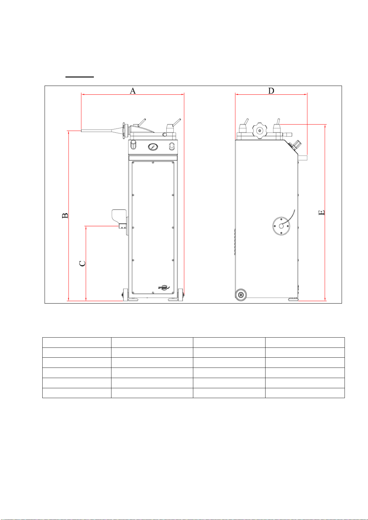
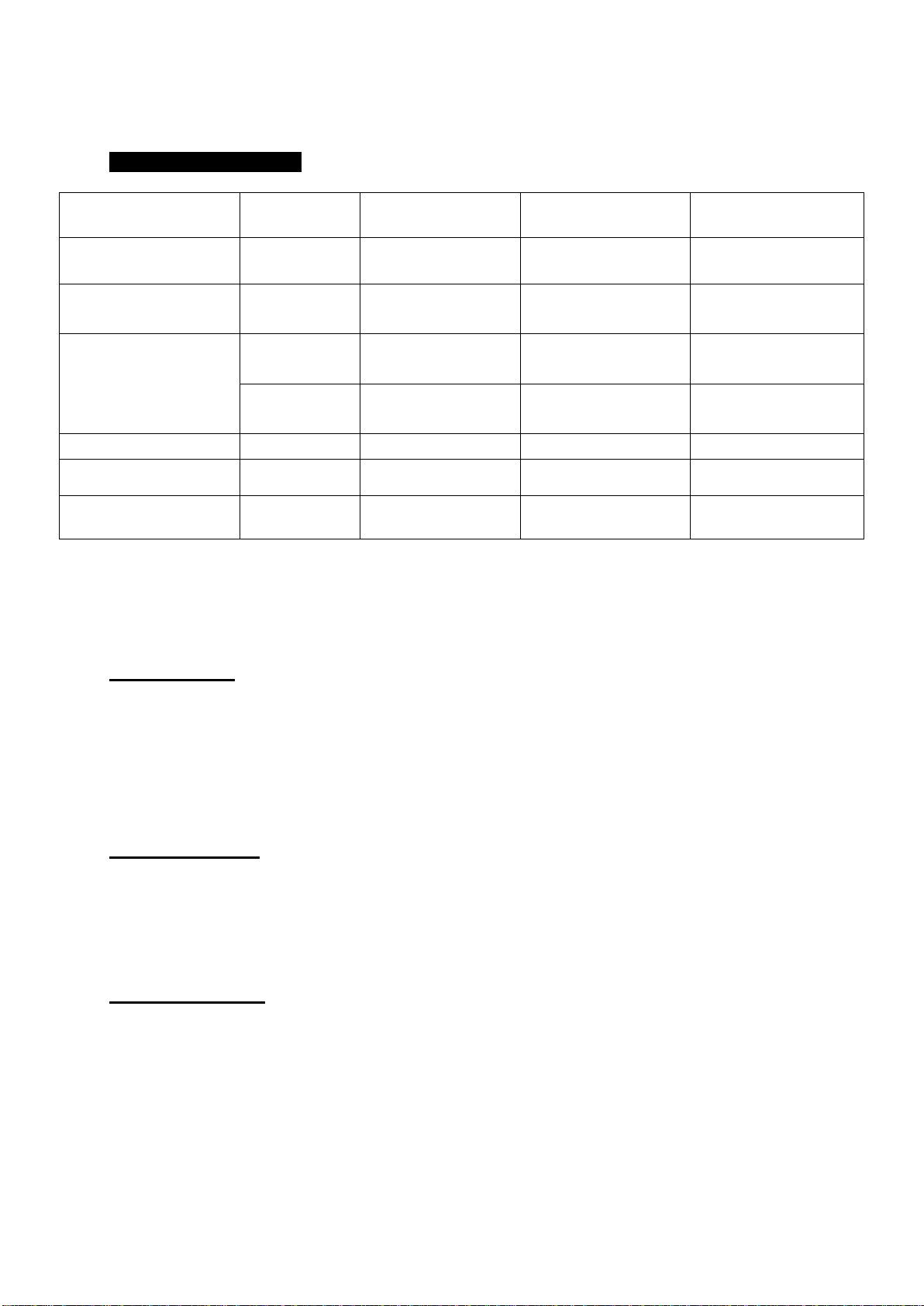
3 Features and specifications ........................................................................3
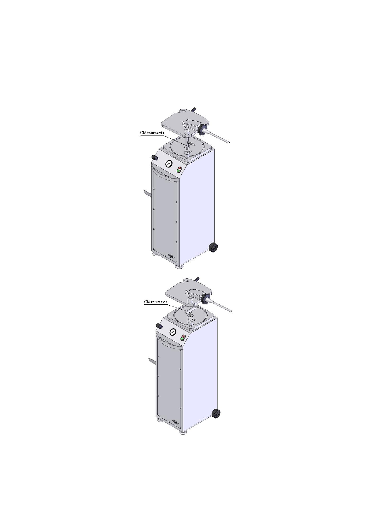
4 Getting started ..............................................................................................4
5 Good using....................................................................................................4
6 Cleaning.........................................................................................................6
7 Maintenance..................................................................................................7
8 Accessories...................................................................................................7
9 Warranty........................................................................................................8
10 Electrical schemes Tri phases ..................................................................9
11 Electrical schemes single phase ............................................................10
12 Exploded scheme.....................................................................................11
Detail (A) :......................................................................................................12
Detail (B) :......................................................................................................13
13 Nomenclature............................................................................................14

1
1Introduction and standards
Fillers VILLA 13, 25 and 40L allow the filling of any kind of flesh
mix mainly for production of sausages.
STANDARDS
These devices meet the requirements of the decrees and safety
standards.
General hygiene and safety laid down in Articles R233-84
R233-106, introduced in the Labour Decree No. 80543 of July
15, 1980.
The control devices and signage, exhibit a degree of protection
IP54 as defined in standard NF 20-010.
All devices present a degree of protection IP245.
Continuous sound pressure level equivalent to the Workstation
measured according to standard NF S31 124 P <70 dB (A)
empty and loaded

2
2Installation and Electrical connection
Position the machine on a stable and solid work surface.
ELECTRICAL CONNECTION
The electrical connection must be performed by qualified
personnel and be conducted in compliance with safety
standards in force.
The line of the power supply must be carried out using a
cable section adapted to the power of the machine and
must include three phase conductors and a grounding
conductor (voltage machine 400v, 50 Hz) or two phase
conductors and a grounding conductor (voltage machine
230v, 50 Hz) .
The power of the machine must be protected by a
breaker.

3
3Features and specifications
SIZES
mm
VILLA 13
VILLA 25
VILLA 40
A
605
660
730
B
975
1103
1210
C
497
497
497
D
430
500
590
E
1014
1148
1270

4
TECHNICAL DETAILS
VILLA 13
VILLA 25
VILLA 40
Cylinder capacity
Litres
13L
25L
40L
Cylinder capacity
for meat weight
± Kg
10kg
20kg
35kg
Engin Power
MONO
1HP-
0,75KW
1,5HP -
1,1KW
-
TRI
0,75HP-
0,55KW
1HP - 0,75
KW
1,5HP -
1,1KW
Oil tank capacity
Litres
6L
9L
15L
Lids / piston
Matière
INOX
INOX
INOX
PWeight
± Kg
87kg
137,5kg
4Getting started
Electrical :
Check the main voltage.
The machine comes standard with three-phase 400 V, 230 V on
request 230 V single phase or three-phase.
On the base:
Attach the pedal on the axis with the two pointed screws
(Allen wrench).
OPERATION:
If the piston does not move by pushing the foot pedal, reverse 2
wire on the plug (Three Phase).

5
5Good using
Do not lay down the machine
Work the paste to a minimum temperature of 10°C.
BEFORE each using, remove the piston to lubricate the
joint.
BEFORE each use, the piston in the down position, oil the
cylidner pfor a proper funcitoning of the joint.
Oil seal cover
Tighten the two bolts of closing the lid
When lowering the piston, the peddle locks in the down
position so the operator does not need to keep his knee on
it. However, the operator must manually move the
peddle to the neutral (center) position when the piston
has reached the bottom of the cylinder.
CAUTION! Failure to do so will cause the motor to
continually run causing the motor to overheat and
possibly burn up.

6
6Cleaning
AFTER EACH USE:
1- Put the piston in upper position.
2- Using the key screwdriver, loosen the set screw of the piston
3- Turn the key to extract the piston
4 - Clean the cylinder by hand with warm water.

7
* The water is discharged through the hole in the bottom of the
cylinder.
* To reassemble the piston, get the hydraulic cylinder in upper
position, and oil the piston seal.
7Maintenance
Regularly, the piston in the down position, check the oil level in
the tank with gauge. Adjust the level if necessary.
8Accessories
1 foot pedal and two pointed screws with six key
sections
1 key screwdriver (piston removal)
1 clamping ring
Cornet No.1 stainless steel Inner diameter 12 mm
Outer diameter 14 mm
Length 230 mm
Cornet No.2 stainless steel Inner diameter 20 mm
Outer diameter 22 mm
Length 236 mm
Cornet No.3 stainless steel Inner diameter 28 mm
Outer diameter 30 mm
Length 236 mm

8
9Warranty
As a manufacturer, we guarantee our equipment for 6 months
against any manufacturing defect.
IMPORTANT :
Electrical parts are excluded from the warranty.
WARRANTY LIMITS :
The warranty applies only to the purchaser and not to third
parties to which the material could be sold.
Our warranty is limited to replacement or repair at no cost
recognized by us defective parts.
The port and the workforce are in all cases on our distributor's
responsability.
Any misuse and/or non respect of specific instructions,
alterations, modifications, or repairs outside the shop of an
authorized dealer,as well as the lack of identification plate,
result in the cancellation of the guarantee.

9
10 Electrical schemes Tri phases

10
11 Electrical schemes single phase

11
12 Exploded scheme
Exploded view :

12
Detail (A) :

13
Detail (B) :

14
13 Nomenclature
NOMENCLATURE FILLERS
DESIGNATION
MODEL 28
VILLA 13
MODEL 55
VILLA 25
MODEL 88
VILLA 40
REPERE
ACCOUPELEMENT PUMP
1505
1505
1505
34
COUPLING MOTOR
1505
1505
1505
33
PEDAL STEEL SHAFT
1547 (1242-0014)
1547 (1242-0014)
1547 (1242-0014)
29
LID RING DELRIN
1551
1552
1553
03
COLLAR CORNET (Black Plastic Nut for Horn)
776 (1242-0015)
776 (1242-0015)
776 (1242-0015)
60
BIELETTE STEEL DISTRIBUTOR CDE
1520
1521
1522
28
AUXILIARY POWER
451
451
451
19
ELECTRICAL BOX (892 220V)
(892US 208V)
892 (1242-0019)
892US(1242-0031)
892 (1242-0019)
892US(1242-0031)
892 (1242-0019)
892US(1242-0031)
55
PLUG GAUGE TANK
267
267
267
45
STOP BUTTON
459-2 (1242-0027)
459-2 (1242-0027)
459-2 (1242-0027)
19
AUXILIARY BLOCK
459-1 (1242-0028)
459-1 (1242-0028)
459-1 (1242-0028)
19
CAP SCREW HCC
260
260
260
STAINLESS STEEL BODY
1520
1521
1522
15
PISTON KEY
280 (1242-0021)
280 (1242-0021)
280 (1242-0021)
06
BELL
1506
1507
1507
35
COLLIER OETICKER
273a
273a
273a
49
COLLIER OETICKER
273
273
273
40
CONE SERIES 60 Ø14
772
772
772
61
CONE SERIES 60 Ø20
773
773
773
62
CONE SERIES 60 Ø32
774
774
774
63
ELBOW PRESSURE PUMP WES 8 LRK
279
279
279
37
WES 8 ELBOW WITH NUT LSV (ONE
SIDE)
278
278
278
22
COVER WITH STEEL CHANNEL
1513
1514
1515
04
SUCTION STRAINER
282
282
282
42
STAINLESS CYLINDER
1500
1501 (1245-0019)
1502-1(1248-0016)
12
DISTRIBUTOR
1503 (1245-0015)
1503 (1245-0015)
1503 (1245-0015)
25
TIP STAINLESS CYLINDER ROD
1538
1539 (1245-0024)
366 (1248-0014)
13
CAPILLARY PRESSURE GAUGE FOR
FLEXIBLE
1535
1535
FLEXIBLE PRESSURE HOSE
292
292
1532
38
FLEXIBLE PRESSURE HOSE
1526
1529 (1245-0025)
1533
53
FLEXIBLE PRESSURE (+ BANJO NUT)
1524
1527
1530
51
FLEXIBLE PRESSURE (+ BANJO NUT)
1525
1528
1531
52
BACKGROUND OF STEEL CYLINDER
1518
341
367 (1248-0017)
10

15
DESIGNATION
MODEL 28
VILLA 13
MODEL 55
VILLA 25
MODEL 88
VILLA 40
REPERE
RANGE DISTRIBUTOR
328
328
328
27
STUD STAINLESS STEEL COVER
1544
1545
1546
02
LIP SEAL CYLINDER BOTTOM
1517 (1242-0017)
343 (1245-0012)
369 (1248-0013)
59
SEAL PASSAGE OF PARTITION
293
293
293
SEAL COVER
1523 (1242-0010)
342 (1245-0010)
368 (1248-0010)
08
JOINT COPPER
296
296
296
58
PISTON RING
1519 (1242-0011)
344 (1245-0011)
370 (1248-0011)
11
GAUGE
1534 (1245-0021)
1534 (1245-0021)
20
ENGINE (220/60/1)
1509 (1242-0022)
1511 (1245-0017)
1511 (1245-0017)
32
PASS WIRE DISTRIBUTOR
306
306
306
26
PEDAL STEEL
1555 (1242-0029)
1555 (1242-0029)
1555 (1242-0029)
31
ADJUSTABLE FOOT
308
308
308
18
PISTON STAINLESS
1500
1501
1502-2(1248-0018)
09
HANDLE COVER
310 (1245-0014)
310 (1245-0014)
310 (1245-0014)
05
PUMP
1504 (1248-0015)
1504 (1248-0015)
1504 (1248-0015)
36
DOOR
1520
1521
1522
48
PRESS POWER GLAND
923
923
923
16
ELBOW PVC FITTING
1537
1537
1537
39
PVC FITTING
313
313
313
44
FITTING T
1536
1536
21
Bulkhead RIGHT
304
304
304
43
STAINLESS TANK
1520
1521
1522
47
CLIP WASHER SHAFT PEDAL
Z/064 (1245-0016)
Z/064 (1245-0016)
Z/064 (1245-0016)
56
CASTER BLACK
315 (1245-0020)
315 (1245-0020)
315 (1245-0020)
17
PEDAL SUPPORT BLACK DELRIN
1548
1548
1548
30
TANK TOP PLATE
1520
1521
1522
46
PIPE « TRICOCLAIR AL TRANS »
634a
634a
634a
50
PIPE « TRICOCLAIR AL TRANS retour
bache »
634
634
634
41
UNION M GHG LR 8 3/8 DISTRIBUTOR
318
318
318
24
CYLINDER
1516
348 (1245-0018)
375
14
LOCK STAINLESS STEEL COVER
1550
321 (1245-0023)
1554
01
VIS BANGO
322
322
322
57
SCREW STEEL PISTON
1540 (1242-0020)
323 (1245-0013)
323 (1245-0013)
07

HOLLYMATICCORPORATION600E.PLAINFIELDROADCOUNTRYSIDE,IL60525Telephone:(708)579‐3700
This manual suits for next models
2
Table of contents
Other Hollymatic Commercial Food Equipment manuals
Popular Commercial Food Equipment manuals by other brands

Dover
Dover Anthony Pass Thru Series installation manual

Perlick
Perlick RS-NDK 1030849 Installation and operation instructions

Victor
Victor RMA65E manual

Bonnet Neve
Bonnet Neve MULTIFRESCO PLUS User instructions

Adventys
Adventys L'OCTOPUS 3500 user manual

Alto-Shaam
Alto-Shaam 500-TH/III Installation, operation and maintanance manual