Holmatro CORE XR 4360 RAM User manual

XR 4360 RAM
Owner’s Manual: 918.269.303 001

2
All rights reserved. You are prohibited from copying or reproducing this manual, any
materials contained herein or any portion hereof in any manner whatsoever without the
express prior written consent of Holmatro.
Holmatro reserves the right to change the contents of this manual at any time without
prior notice. Holmatro also reserves the right to change any part or component of any
machine referenced in this manual at any time without prior notice.
This manual is intended for use solely with the basic version of each piece of equipment
and each product referenced and should not be used in connection with any modified,
altered or adapted version of any piece of equipment without the express prior written
consent of Holmatro.
Additional information on adjustments, maintenance and repair of any product contained
herein will be provided upon written request of the technical department of your
supplier. If not provided, contact Holmatro directly.
EXCEPT AS EXPRESSLY SET FORTH ON THE ENCLOSED WARRANTY
CARD, HOLMATRO MAKES NO OTHER WARRANTY OR
REPRESENTATION, EITHER EXPRESS OR IMPLIED, WITH RESPECT TO
THE STATEMENTS CONTAINED HEREIN. HOLMATRO HEREBY
EXCLUDES ANY AND ALL IMPLIED WARRANTIES, INCLUDING
WARRANTIES OF MERCHANTABILITY AND FITNESS FOR A
PARTICULAR PURPOSE.
IN NO EVENT WILL HOLMATRO BE LIABLE FOR DIRECT, INDIRECT,
SPECIAL, INCIDENTAL OR CONSEQUENTIAL DAMAGES ARISING OUT
OF USE OF THIS MANUAL OR ANY STATEMENTS CONTAINED THEREIN.
SOME STATES DO NOT ALLOW THE EXCLUSION OF IMPLIED
WARRANTIES OR LIABILITY FOR INCIDENTAL OR CONSEQUENTIAL
DAMAGES, SO THE ABOVE LIMITATION OR EXCLUSION MAY NOT
APPLY TO YOU.
IF ANY PROVISION CONTAINED HEREIN SHALL BE UNLAWFUL, VOID
OR FOR ANY REASON UNENFORCEABLE, THEN THAT PROVISION
SHALL BE SEVERED FROM THE STATEMENT AND SHALL NOT AFFECT
THE VALIDITY AND ENFORCEABILITY OF THE REMAINING
STATEMENTS CONTAINED HEREIN.

3
1. Introduction
We congratulate you on this purchase. Be sure to read and understand this user manual before using
the tool. This user manual covers the basic aspects for the safe use and operation of this equipment.
First of all check that your equipment is complete and undamaged. Notify your Holmatro dealer
immediately if the equipment is damaged or incomplete, and do not use the equipment.
This equipment is designed for use by professional, fully trained fire and rescue personnel.
This is a double-acting hydraulic tool designed to be driven only by a Holmatro hydraulic pump. The
entire system operates with mineral oil hydraulic fluid to an allowable pressure of 720 bar. There are
two versions of the tool available.
1.) A Twin-line version with a separate input pressure line and return line.
2.) A Core™ technology version with the input pressure line contained inside the return line
Follow these instructions to ensure your safety and to keep your equipment in good condition.
2. Safety Symbols
THIS IS THE SAFETY ALERT SYMBOL. IT IS USED TO ALERT YOU TO
POTENTIAL PERSONAL INJURY HAZARDS. OBEY ALL SAFETY
MESSAGES THAT FOLLOW THIS SYMBOL TO AVOID POSSIBLE
INJURY OR DEATH.
DANGER indicates an imminently hazardous
situation which, if not avoided, will result in death
or serious injury.
WARNING indicates a potentially hazardous
situation which, if not avoided, could result in
death or serious injury.
CAUTION indicates a potentially hazardous
situation which, if not avoided, may result in minor
or moderate injury.
CAUTION used without the safety alert symbol
indicates a potentially hazardous situation which, if
not avoided, may result in property damage

4
3. Safety Instructions
Study these instructions carefully before operating this
equipment.
* Never use a Core™ Technology product with a Twin-line hose product.
* Use this equipment only for jobs for which it is designed. If in doubt or not clear, be sure to
consult your dealer.
* Always wear personal protection equipment such as safety goggles, helmet, gloves, protective
clothing and safety shoes.
* Keep spectators at sufficient distance.
* Stand on stable ground and use both hands to hold and/or operate the equipment.
* Hold the equipment only at the appropriate places, i.e. at the deadman's handle and the carrying
handle.
* Stabilize the objects the tool will be used on.
* Never cut parts under hydraulic and/or pneumatic pressure, at live voltage or mechanical stress.
* Stop immediately if the blades are bent open during cutting.
* The equipment is not designed for lifting or raising loads.
* In the event of oil leakage, stop immediately and consult the troubleshooting list.
* In the event of unfamiliar noise, vibration or other unusual behavior, stop immediately and
consult your dealer.
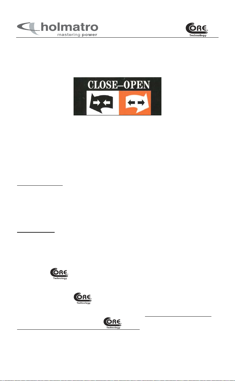
* For Twin-line tools, never disconnect the quick-action couplings when the pump is in operation
and when the pressure relief valve of the pump is in the "Operation" position.
* Store the unit with the blades slightly crossed.
* The safety valves between the couplers must never be adjusted. In the event a problem develops
with the safety valve, contact your dealer.
* The equipment must only be operated with non-toxic mineral base hydraulic oil distributed by
Holmatro.
* Use only Holmatro accessories and parts.
* Observe the maintenance instructions.
* Only trained service technicians, certified by Holmatro, are allowed to repair this equipment.
* Replace safety symbols / pictograms and / or information labels if worn.
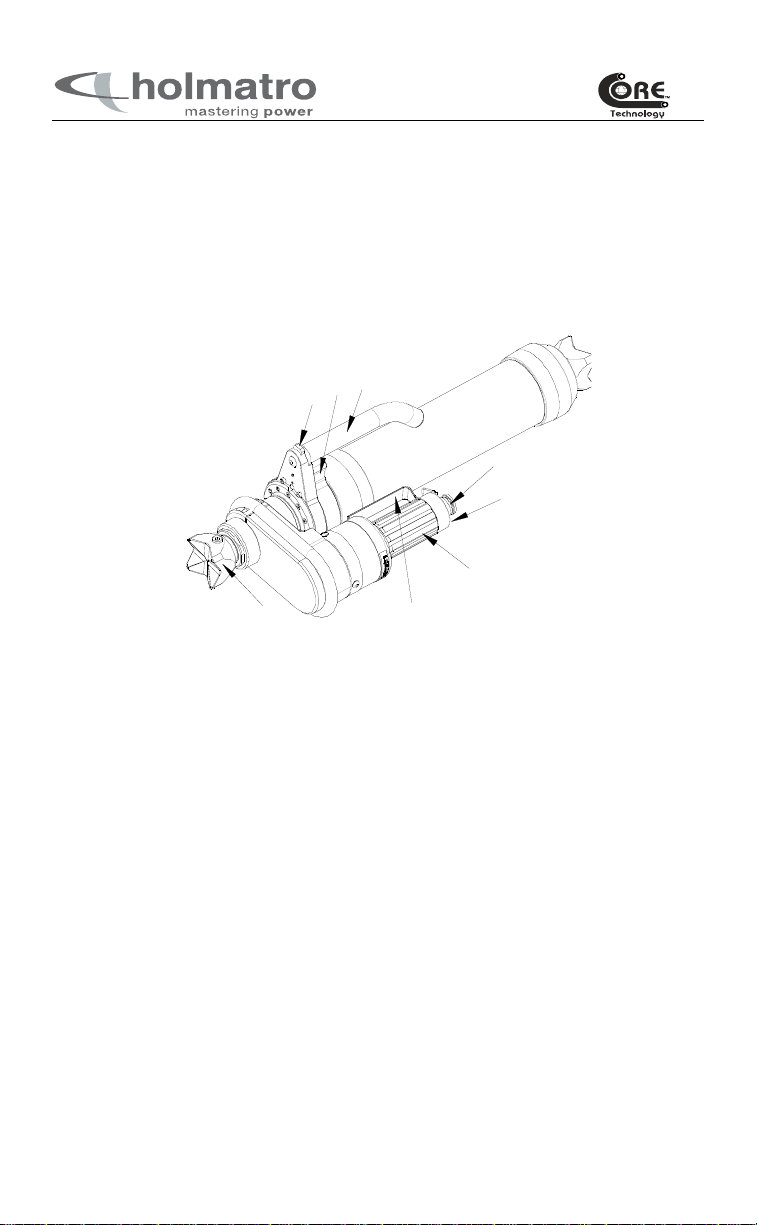
4 The tool is equipped with the following
labels/stickers:
1. Wear personal protection equipment
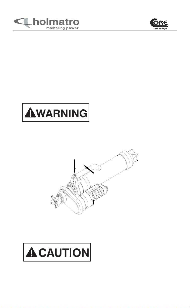
2. Dead-man's handle operating direction
3. Warning to prevent parts of the body being pinched/cut off
4. Product identification: model, serial number, year of construction, etc.
5. Grease and lubrication label.
6. Safety / warning Label.

5
5. Description: model XR4360
5.1 Product identification
A. Quick-action couplings E. Cross heads
A. Safety relief valve F. Handle guard
B. Dead-man's handle G. Carry handle Lock
C. Carrying handle H. Mechanical Lock
A
B
C
D
EF
GH
5.2 Specifications
Allowable operating pressure : 10,500 psi (720 bar)
Max. Force (NFPA-1936 HSF)* : 22,385 lbs (99.6 kN)
Max. spreading travel (hydraulic) : 13 3/4 (350 mm)
Max. spreading travel (mechanical) : 11 3/4” (298 mm)
Full travel distance : 30 1/2” (775 mm)
(including intermediate
non moving Part)
Weight, ready for use‡ : 35 lbs (15.9 kg)
Weight, ready for use† : 32 lbs (14.5 kg)
Closed Dimensions ‡ (LxWxH) 24 ½” x 8 ¼” x 6 ¾” (625 x 210 x 170 mm)
Closed Dimensions † (LxWxH) : 24 ½” x 8 ¼” x 6 ¾” (625 x 210 x 170 mm)
Net required oil volume : 21.7 cu in (356 cc)
* The maximum (HSF) and minimum (LSF) forces are equivalent.
‡ Twin-line
† Core™

6
6. Operation
The oil from the hydraulic pump is supplied to the unit via high-pressure hoses. The oil returns at
atmospheric pressure to the pump if the dead-man's handle is in the neutral position.
Fig. 1. Control handle label.
Oil is admitted under the piston if the dead-man's handle is in the “open” position. The arms will
then open. The oil above the piston flows back to the pump.
Oil is admitted above the piston if the dead-man's handle is in the “close” position. The arms will
close. The oil under the piston flows back to the pump.
The dead-man's handle always returns to the neutral position when released.
TWIN-LINE TOOLS
The hydraulic system in the unit is provided with a safety valve. This safety valve prevents
excessive pressure in the tool if the return line to the pump is blocked or disconnected. Never
change the setting of this safety valve. Oil will discharge from the rear of the tool if the return hose
becomes blocked or disconnected while the pump pressure relief valve is in
“PRESSURE”/”OPERATION” position. If this happens, first switch the pump pressure relief valve
to the “NEUTRAL” position, and then re-connect the return hose of the tool.
CORE™ TOOLS
The hydraulic system in the unit is provided with a safety valve. This safety valve prevents
excessive pressure in the tool if the return line to the pump is blocked. Never change the setting of
this safety valve. Oil will discharge from the rear of the tool if the return hose becomes blocked
while the pump is running. If this happens, first switch the pump engine/motor to OFF and
disconnect the hose. Then connect a new hose.
When Holmatro valve blocks are mounted on your Holmatro power unit, the manual
operated release valve is no longer needed. As soon as the hose is connected, oil is flowing through
the hose’s inner shell and returning back to the tank of the pump through the hose’s outer shell.
When a rescue tool with the adaptor installed has been connected to the hose, oil will flow
into the tool. To change from one rescue tool to another, the user simply disconnects the rescue tool
from the hose and connects the alternate rescue tool to the hose. Oil always flows from the female
coupler into the male coupler for Holmatro systems.

7
mechanical plunger
lock position
Carrying handle
lock
6.1 Spreading
Extend the mechanical plunger.
Hold the tool with one hand on the deadman’s handle, and the other hand on the
carrying handle.
Lift the deadman’s handle slightly to take the weight off the locking mechanism.
Push the mechanical lock (A) to the left or the right to release the locking mechanism.
Lift up the mechanical plunger (B) to the desired height.
Release the mechanical lock. Make sure that the mechanical plunger is locked in one of
the grooves.
Once the ram is in position, operate the deadman’s handle to extend the hydraulic
plunger.
A
B
Mechanical plunger
with grooves
Make sure that the mechanical lock is in the locked
position before operating the deadman’s handle.
Operating the ram while the mechanical lock is
unlocked can cause damage to the tool.

8
Retract the mechanical plunger.
Hold the tool with one hand on the deadman’s handle, and the other hand on the
carrying handle.
Operate the deadman’s handle to retract the hydraulic plunger.
Lift the deadman’s handle slightly to take the weight off the locking mechanism.
Push the mechanical lock (A) to the left or the right to release the locking mechanism.
Lower the mechanical plunger (B) to the desired height.
Release the mechanical lock. Make sure that the mechanical plunger is locked in one of
the grooves.
Rotate the carrying handle.
The carrying handle can be rotated around the cylinder between two lock positions.
Never set the carrying handle in an unlocked
position. The mechanical plunger may extend out
of the cylinder if the locking mechanism is not
engaged.
Push the lock button (A) to release the locking mechanism.
Rotate the carrying handle to the next locking position. The locking positions are
located 180°apart. The carrying handle should never be left in the unlocked position.
Release the lock button to lock the carrying handle in position.
A
B
6.2 Pulling
The 4360 ram is not rated for pulling. This tool
should not be used for any pulling operations.

9
7. Use
7.1 Initial use (first time only)
* Check the equipment for damage. Do not use the equipment if it is not in good
condition. Notify your dealer.
* Check whether the guarantee registration card has been supplied and filled in.
* Check whether the accessories are correctly mounted.
7.2 Preparation for use
* Check the operation of the dead-man's handle (return to neutral position).

10
7.2.1 Coupling
The unit is equipped with different quick-action couplings, i.e. "male" and "female".
For Twin-line tools, never connect or
disconnect the quick-action coupling when
the pump relief valve is set to “PRESSURE”/
“OPERATION”. Set the pump relief valve to
its "NEUTRAL" position before coupling or
uncoupling hoses and/or tools.
To couple the hoses using the flat face coupler:
1. Remove the dust caps from both the male and female couplers.
2. Insert the male coupler into the female coupler and push.
3. The coupler’s locking ring (A) will move forward to show the coupler is locked.
4. Check to make sure the connection is made by pulling on the two couplers.
To uncouple the hoses using the flat face coupler:
1. Push the hose coupler gently forward into the tool/pump coupler.
2. Turn the locking ring (A) of the coupler ¼ turn counterclockwise when holding it
in your hand pointing away from you (direction of large arrow on coupler) and
pull back on the locking ring (direction of small arrow on coupler). l
3. Remove the male coupler from the female coupler if it has not released
completely.
4. Make sure you put the dust caps back onto the couplers when not in use. This is
an important step to keep dirt and foreign objects from getting into the coupler.
Twin-line female coupler
Core™ female coupler
Clean the female coupler by removing any dirt, oil, etc. with a clean dry rag. To ensure the automatic
locking capability of the coupler, the couplers and dust caps should be checked periodically and
cleaned by following the simple steps below:
1. Rinse the coupler and dust cap with lukewarm water and a soft soap solution.
2. When the coupling is dry and free from water, lubricate the flat end of the coupling (B) with
Holmatro recommended hydraulic oil or by spraying WD-40 onto the end.
3. Lubricate the locking sleeve by spraying WD-40 carefully in the area (C) between the back
part and the locking sleeve.
4. Connect the nipple into the coupling and see if the locking sleeve easily turns itself to the lock
position. Check by pulling the locking sleeve straight back. The nipple should not disconnect.
5. To disconnect the nipple, turn the locking sleeve and pull it backward.
6. Repeat steps 4 and 5 a few times to assist internal lubrication of the locking sleeve.

11
7.2.2 Use
Turning the dead-man's handle clockwise has the same result in all Holmatro
equipment (from 01.01.95): the functional parts are opened. The functional parts are
closed by turning counter-clockwise. As soon as the dead-man's handle is released it
automatically returns to its neutral position and the unit stops operating immediately.
7.2.3 Spreading
Ensure that the original crossheads are
attached correctly.
The pistons are extended by turning the
dead-man's handle clockwise and objects can be pushed apart. The pump
automatically supplies the required pressure as soon as the cross heads experience any
resistance.
Prevent sharp protrusions from touching
the piston during spreading. Damage leads
to leakage through the seal.
Prevent the cross heads from sliding from
the load. Use the optional ram support for
weakened car bodies (see accessories
section). Use only original Holmatro
accessories and attach them correctly.
7.2.4 Shutting down
On completion of the work retract the pistons back into the cylinders. Check that the
pump relief valve is in its "neutral" position before uncoupling. Remove any dirt from
the couplings and the dust caps to prevent penetration into the hydraulic system. Take
the dust caps apart and place them on the tool’s couplings.
When the retracting movement stops,
spread the pistons again over a small
distance of approx. 1/4 inch to relieve any
pressure in the tool and store the tool in
that condition.
7.2.5 Cleaning and storage
Clean the unit and any accessories used before storage.
* Clean all quick-action couplings and dust caps. Ensure that the dust caps are
clean and installed.
* Check the tool for external damage and/or oil leakage.
* Check the operation of the dead-man's handle.
* Dry the unit if it has been used in wet conditions. Lightly oil the steel parts.
* Clean the tool with a mild soap solution and dry thoroughly.

12
7.3 Important additional user information
The hydraulic hoses belonging to the hydraulic
system need attention. Observe the following
points:
1. Do not use hoses without proper anti-kink devices and prevent kinking behind the
attachment.
2. Prevent kinking of the hoses and never bend the hoses beyond their minimum bending
radius
(89 mm) (3 ½ in).
3. Do not pull the hoses to move tools or pumps.
4. Prevent twisting of the hose.
5. Do not use the hoses to keep the equipment in position and especially not if the hoses
are pressurized.
6. Do not store hoses with the ends coupled together.

13
8. Troubleshooting
8.1 The quick-action couplings cannot be connected.
1 Check tool control handle
position Handle in open or
close position Release control handle
to neutral position
Control handle in neutral
2
Twin-line: Check for pressure in
the hose.
---------------------------------------
Core:Check for pressure in the
hose.
Hose pressurized, but
not pre-connected to
pump/tool.
--------------------------
Release pressure in
hose using Pressure
Relief Device (PRD)
Hose pressure relieved
3
Twin-line: Check for pressure in
the tool.
---------------------------------------
Core™: Check for pressure in
the tool.
Tool pressurized, but
not pre- connected to
pressure or return
hoseline.
--------------------------
Tool pressurized, but
not pre- connected to
hoseline
Release pressure in
tool using PRD
----------------------
Release pressure in
tool using PRD
Tool pressure relieved
Pump pressure relieved(Twin-
line) or pump not pressurized
(Core™)
5 Check the coupling locking
sleeve location or dirt in coupler Incorrect position or
dirt in coupler Release locking
sleeve. Clean coupler
Locking ring released/Coupler
clean
6 Consult your Dealer
4
Twin-line: Check for pressure in
the pump.
---------------------------------------
Core™:Check for pressure in
the pump.
Pump pressurized, but
not pre-connected to
hose.
--------------------------
Pump pressurized but
not pre-connected to
hose
Release pressure at
pump using
Operation/Release
handle.
----------------------
Turn off pump &
Consult your Dealer

14
8.2 The quick-action couplings cannot be disconnected.
1 Check tool control handle
position
Handle in open or
close position Release control
handle to neutral
position
Control handle in neutral
2
Twin-line: Check the position of
the pump pressure relief valve.
---------------------------------------
Core™: Pump only is
pressurized.
Valve in Operation
position.
----------------------
System not releasing
pressure
Turn valve to
“RELEASE”.
----------------------
TURN OFF PUMP
Release pressure at
valve block relief
valve by turning
valve stem all the
way in .
clockwise
Consult your
Dealer
Valve position in RELEASE
(Twin-line) or pump not
pressurized (Core™)
3 Check the coupling locking
sleeve location Incorrect position Release locking
sleeve
Locking ring released
4 Consult your Holmatro Dealer
8.3 Hydraulic oil is leaking from the tool safety valve.
1
Twin-line: Check quick-action
coupling connections between
pump and tool.
---------------------------------------
Core™: Check quick-action
couplings
Loose or
disconnected
couplings
-----------------
Damaged
coupler(s).
Release pressure at
pump using
Operation/Release
handle and re-connect
the couplings.
--------------------------
Consult your Dealer
Couplings okay
2 Consult your Holmatro Dealer

15
8.4 The connected equipment is not operating - or not
properly.
1
Check the pump hydraulic oil
level.
No or low
hydraulic fluid
Add recommended
hydraulic fluid up
correct level.
Hydraulic fluid level correct
2
Twin-line: Check the coupler
connections.
---------------------------------------
Core: Check the coupler
connections.
Incorrect or
incomplete
coupling.
Release pressure at
pump and reconnect.
--------------------------
Reconnect couplings
Couplings correct
3
Twin-line: Check the position of
the pump pressure relief valve.
---------------------------------------
Core™: Check the pump valve
block relief valve stem.
Valve in Neutral
position.
----------------------
Valve stem is all
the way in
Turn valve to
“OPERATION”.
--------------------------
Turn valve stem all the
way out .
Valve position okay
4 Consult your Holmatro Dealer
8.5 The dead-man’s handle is not operating properly.
1 Check control handle for external
damage Control handle
damaged Contact your
Holmatro Dealer
Control handle okay
2
Check if the dead-man handle is
stuck in any position. The
control handle should move
freely.
Dead-man handle
stuck
Contact your
Holmatro Dealer
Dead-man handle okay.
3 Consult your Holmatro Dealer

16
8.6 The ram piston does not extend.
1 Check control handle position Control handle in
neutral position Turn control handle to
“OPEN” position
Control handle in “OPEN”
position
2
Tool was pressurized in the
closed position.
Internal blocking
valve is activated
Note:A noise or
clicking sound
may be heard
when attempting
to extend the ram
when the blocking
valve is activated.
Release the blocking
valve.
a. Turn control handle
to “CLOSE” position
momentarily.
b. Turn handle to
“OPEN” position. The
blocking valve should
be released and the
piston will extend.
Blocking valve release procedure
completed.
3 Consult your Holmatro Dealer
Consult your dealer in case of other problems or if the solutions provided above do not have the
required results. In case of failure or repairs, always specify the model and serial number of the
equipment to your dealer.
ALWAYS SHIP THE TOOL IN ITS ORIGINAL SHIPPING BOX.

17
9. Maintenance
Wear personal protection equipment during
maintenance. Ensure that any spent replaced
hydraulic oil is collected and disposed of in a
responsible manner, think of the environment.
9.1 Regular maintenance (minimum every 3 months)
It is necessary to carry out regular maintenance. Increased use will necessitate more frequent
maintenance intervals. Consult your dealer.
* Check whether the safety symbols and product identification labels are still present. If
not, consult your dealer.
* Check the functions of the dead-man's handle.
* Check the accessories.
* Check the hoses, quick-action couplings and dust caps.
* Check the operation of the equipment.
9.2 Annual maintenance
With the proper care and correct preventive maintenance this unit will ensure many years of
safe use. We recommend having the unit checked at least once a year by a trained technician
with the proper knowledge and the necessary tools. Your dealer can carry out the annual
maintenance on a contract basis on your behalf, if desired. This will ensure good and safe
operation.
9.3 Five yearly maintenance and testing
We advise you to have the equipment checked and tested by your dealer or other body
certified by Holmatro after a maximum of five years of use. Consult your dealer for further
details.
9.4 Long-term storage
* Ensure that the equipment is completely depressurized.
* Store the equipment in a dry, well-ventilated area. Use additional preservatives on the
external steel parts.
10. Scrapping
The unit can be scrapped at the end of its service life and the various parts may be recycled.
Collect the hydraulic oil and dispose of it separately. The unit consists of steel, aluminium,
neoprene (seals) and plastic. The unit does not contain any pressurized components.
Also, consult your dealer about scrapping.

18
11. Technical information
Telescopic ram Model: 4360.
Made in the USA
The 4360 ram is not designed to be used as a jack and
should never be used as such. Never work under a load
lifted by the 4360 ram. To safely lift a load, you may use
Holmatro’s air lifting bag. Properly chock the load before
lifting.
Qualified persons authorized by Holmatro may only make repairs and/or service to Holmatro®
rescue tools. An active and presently authorized Holmatro dealer may only disassemble the sealed
parts. Contact your dealer for further advice if other problems occur. In the event that you are
unable to contact your dealer, contact Holmatro at:
Holmatro, Inc.
505 McCormick Dr.
Glen Burnie, MD 21061
Fax: (410) 768-4878
Tel: (410) 768-9662
Website: www.holmatro-usa.com

19
HOLMATRO DEALER: TEL: FAX:
TOOL MODEL NUMBER: TOOL SERIAL NUMBER:
SERVICE RECORD:
DATE REPAIR/SERVICE
DESCRIPTION SERVICE
TECHNICIAN
Please make copies of this sheet as needed for future use.

20
Table of contents
Other Holmatro Jack manuals