OTC 5237 User manual
Sheet No.
Issue Date: Rev. C October 23, 2017
© Service Solutions U.S. LLC
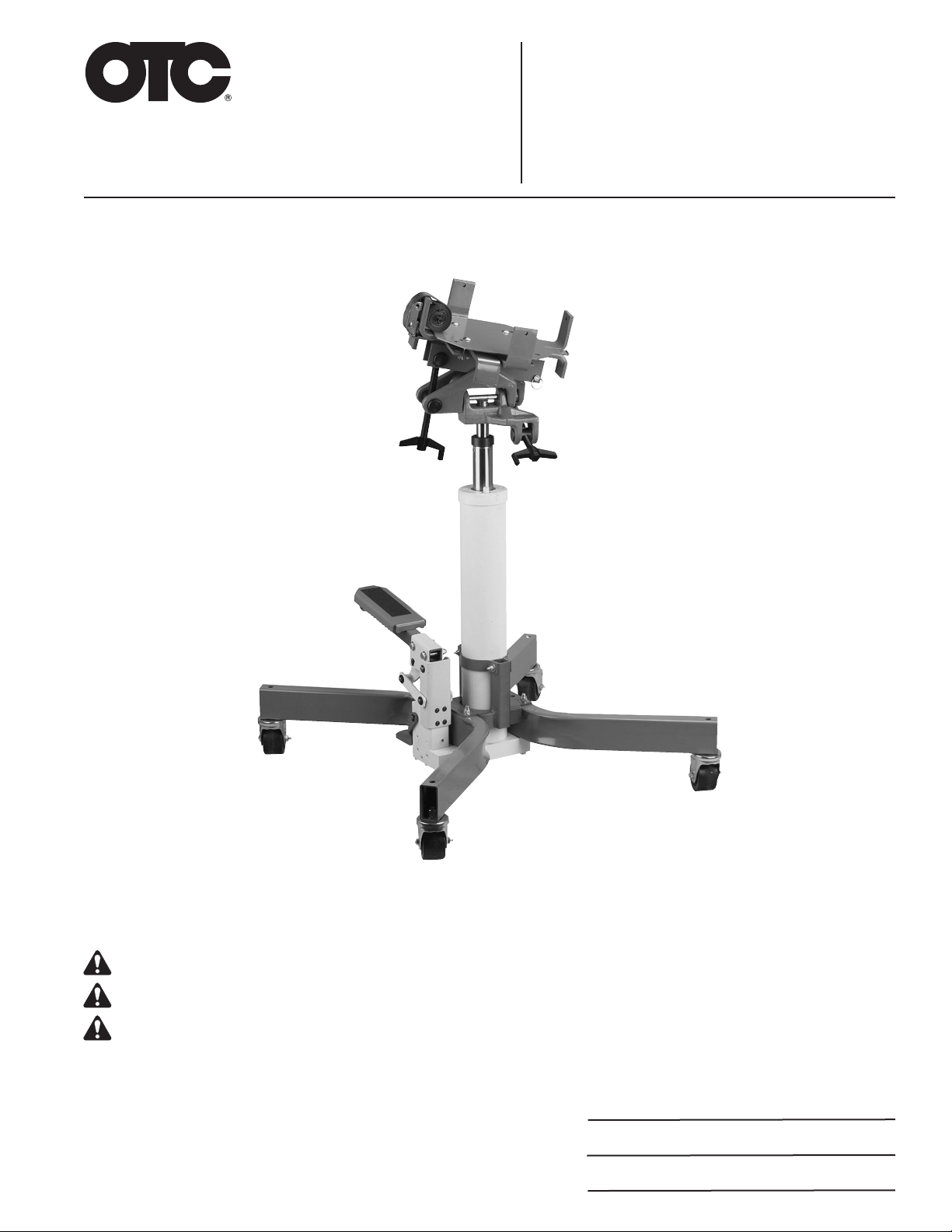
High Lift Transmission Jack
Max. Capacity: 453.59 kg (1,000 lbs.)
Explanation of Safety Signal Words
The safety signal word designates the degree or level of hazard seriousness.
DANGER: Indicates an imminently hazardous situation which, if not avoided, will result in death or serious injury.
WARNING: Indicates a potentially hazardous situation which, if not avoided, could result in death or serious injury.
CAUTION: Indicates a potentially hazardous situation which, if not avoided, may result in minor or moderate injury.
CAUTION: Used without the safety alert symbol indicates a potentially hazardous situation which, if not avoided, may
result in property damage.
Description:
Use to install and remove vehicle
transmissions for repair.
Form No. 560935
Parts List &
Operating Instructions
for: 5237
655 EISENHOWER DRIVE
OWATONNA, MN 55060-0995 USA
PHONE: (507) 455-7000
TECH. SERV.: (800) 533-6127
FAX: (800) 955-8329
ORDER ENTRY: (800) 533-6127
FAX: (800) 283-8665
INTERNATIONAL SALES: (507) 455-7223
FAX: (507) 455-7063
1 of 6

Safety Precautions
WARNING: To help prevent personal injury and/or equipment damage,
• Study, understand, and follow all safety precautions and operating instructions
before using this transmission jack. If the operator cannot read these instructions,
operating instructions and safety precautions must be read and discussed in the
operator’s native language.
• Wear eye protection that meets ANSI Z87.1, CE EN166, AS/NZS 1337, and OSHA
standards.
•
Only qualied operators may install, operate, adjust, maintain, clean, inspect, or
transport this transmission jack.
• A load must never exceed the rated lifting capacity of the jack.
• Do not lift or support the vehicle with this jack. Place support stands under the
vehicle before starting repairs.
• Only use the jack on a hard, level surface.
• Center the load on the jack saddle. Off center loads can damage the seals in the
hydraulic cylinder and cause jack failure.
• Never move the jack with a load any higher off the ground than necessary. Slowly
and carefully move the jack around corners because the load could tip. Stay clear
of a lifted load.
• Lower the jack slowly and carefully while watching the position of the load.
• Do not use this transmission jack for anything other than its intended purpose.
• No alteration shall be made to this product.
• Inspect the condition of the transmission jack before each use. Do not use if damaged, altered, or
in poor condition.
• Do not use adapters with this jack unless supplied by OTC.
• Use only anti-wear hydraulic jack oil with a 215 SUS viscosity rating at 37.78° C (100° F). The use of
alcohol, hydraulic brake uid, or transmission oil could damage seals and result in jack failure.
This guide cannot cover every situation, so always do the job with safety rst.
Setup Instructions
1. Remove the transmission jack from the pallet, and attach the casters using the hex nuts provided.
2. Remove the hex nuts holding the head assembly plate, and replace them with the wing nuts provided.
3. Remove the shipping oil plug, and replace it with the vented oil plug provided.
4. The transmission jack is shipped with hydraulic oil in the cylinder reservoir. Before using the jack for the
rst time, press the release pedal to open the release valve, and operate the foot pump eight full strokes
to distribute the oil.
Operating Instructions
1. Follow the vehicle's recommended service procedure for removal of the component.
2. Position the jack under the vehicle.
3. Raise the jack by operating the foot pump until the saddle touches the component.
4. Adjust the support brackets to t the component.
5. Use the tilt crank to align the saddle with the component.
6. Finish raising the jack to the component. Secure the strap assembly around the component.
Parts List & Operating Instructions Form No. 560935, Sheet 1 of 6, Back

Sheet No.
Issue Date: Rev. C October 23, 2017
© Service Solutions U.S. LLC
Maintenance
1. Use only anti-wear hydraulic jack oil. The use of alcohol, hydraulic brake uid, or transmission oil could
damage the seals in the cylinder and result in jack failure.
2. Check the oil level periodically:
a. Lower the jack to its lowest position.
b. Remove the ller plug.
c. Add hydraulic oil (215 SUS viscosity at 37.78° C [100° F]) until the oil level is within 50.8 mm (2 inches) to
63.5 mm (2.5 inches) of the ller hole opening.
d. Install the ller plug.
3. Lubricate the foot pump pivot points as needed with SAE 30 motor oil to prevent premature wear.
4. Keep the jack clean and well lubricated to prevent foreign matter from entering the hydraulic system.
Bleeding Air from the Jack
1. Lower the jack to its lowest position.
2. Remove the reservoir ller plug. Add hydraulic oil (215 SUS viscosity at 37.78° C [100° F]) until the oil level
is within 50.8 mm (2 inches) to 63.5 mm (2.5 inches) of the ller hole opening.
3. Remove the foot pedal and piston assembly by removing the button head screws.
4. Fill the foot pedal piston bore and rod internal spring cavity with hydraulic oil.
5. Plug the rod internal spring cavity, and quickly install the rod into the rod bore. Note: This must be done
quickly to ensure the cavities are lled with oil and not air.
6. Using the button head screws, reattach the foot pedal assembly.
7. Pump the foot pedal to extend the cylinder to a full stroke, and then retract. Repeat this two or three times.
8. Check the hydraulic oil level and add more if needed.
Inspection and Maintenance
CAUTION: To prevent personal injury,
• Only qualied personnel shall perform inspections to this transmission jack.
•Before each use, an approved inspector must inspect the transmission jack for bends, cracks,
dents, elongated holes, or missing hardware. If damage is found, discontinue use.
Parts List & Operating Instructions Form No. 560935
2 of 6

Parts List & Operating Instructions Form No. 560935, Sheet 2 of 6, Back
Troubleshooting Guide
Repair procedures must be performed in a dirt-free environment by qualied personnel who are familiar with
this equipment.
Trouble Cause Solution
Jack fails to extend or extends 1. Low oil level. 1.Fill to correct oil level.
partially.
Incomplete or spongy cylinder 1. Low oil level. 1.Fill to correct oil level.
response when foot pedal is 2. Air in system. 2.Bleed air from system.
pumped.
Abnormal leakage through 1. Low oil level. 1.Fill to correct oil level.
unit breather.
Jack fails to extend when foot 1. Release valve malfunction. 1.Pump foot pedal with release valve
pedal is pumped. open.
2. Contamination. 2.Disassemble and clean unit.
3. Cylinder packing failure. 3.Install repair kit.
Cylinder creeps. 1. Load exceeds maximum 1.Reduce load.
lifting capacity.
2. Release valve is leaking. 2.Flush release valve by pumping foot
pedal with release valve open.
Cylinder doesn't retract when 1. Light load. 1.Unit requires 35 lbs. to return.
release pedal is activated. 2. Cylinder is binding. 2.Disassemble unit; replace defective
parts.
Cylinder doesn't extend. 1. Contamination. 1.Disassemble and clean unit.
2. Bad packing. 2.Install repair kit.
Cylinder extends when foot pedal 1. Release valve malfunction. 1.Flush release valve by pumping foot
is pressed, and retracts as foot pedal with release valve open.
pedal retracts. 2. Contamination. 2.Disassemble and clean unit.
Sheet No.
Issue Date: Rev. C October 23, 2017
© Service Solutions U.S. LLC
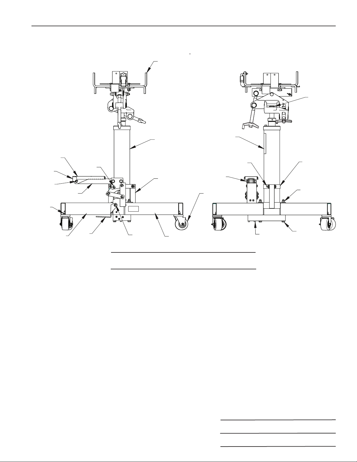
10 556826 2 Leg Base
15 556840 1 High Lift Transmission
Jack
16 556830 1 Head Assembly
No.
Req'd Description
Part
No.
Item
No.
Parts List & Operating Instructions Form No. 560935
Parts Lists
3 of 6
Feuillet nº
Date de publication : Rév. B,avril 2013
© Service Solutions U.S. LLC
10 556826 2 Support du pied
15 556840 1 Cric pour transmission
haute levée
16 556830 1 Tête
Qté
requise Description
Nº
de réf.
Article
nº
Liste des pièces et consignes d’utilisation Formulaire nº 560935
Listes de pièces
1
2
3, 4, 5
7, 8, 9
6
10 10
11 12, 4
13
14
15
16
17
18, 19, 20
21, 22, 29
23 24, 25
26, 25
27
28
3 sur 6
30

Parts List & Operating Instructions Form No. 560935, Sheet 3 of 6, Back
7 4 Flat Washer —
12.7 mm x 3 mm
(.500 in. x .120 in.)
8 4 Metric Hex Nut —
M12 x 31.8 mm
(1.25 in.)
9 4 Lockwasher —
for 12.7 mm (1/2 in.) bolt
13 4 Swivel Caster
No.
Req'd Description
Caster Kit 565522
Item
No.
17 1 Logo Decal
18 4 Washer — for 6.35 mm
(.25 in.) bolt
19 2 Hex Locknut — 1/4-20
20 2 Bolt — 1/4-20 x 55.88 mm
(2.25 in.)
23 3 Socket Head Cap Screw
— 1/4-20 x 50.8 mm (2 in.)
24 4 Hex Head Cap Screw
25 12 Plain Washer —
for 9.53 mm (.375 in.) bolt
26 4 Hex Nut
28 1 External Retaining Ring
— for 25.4 mm (1 in.)
dia. shaft
N/A 1 Breather Filter
30 1 Clevis Pin
No.
Req'd Description
Hardware Kit 565524
Item
No.
4 2 External Retaining Ring
— for 9.53 mm (.375 in.)
dia shaft
11 1 Foot Pedal
12 1 Clevis Pin
No.
Req'd Description
Release Pedal Kit 565526
Item
No.
14 1 Support Bracket
18 4 Washer — for 6.35 mm
(.25 in.) bolt
19 2 Hex Locknut — 1/4-20
20 2 Bolt — 1/4-20 x 55.88 mm
(2.25 in.)
27 2 Support Strap
No.
Req'd Description
Support Kit 565525
Item
No.
1 1 Grip Pad
2 1 Pedal
3 2 Round Hole Washer
4 2 Retaining Ring
5 1 Clevis Pin
6 1 Pedal Lever
21 2 Hex Locknut – .376-16
22 2 Hex Head Cap Screw
– 3/8-16 X 55.88 mm
(2.25 in.)
29 4 Washer, .375
No.
Req'd Description
Foot Pedal Kit 565523
Item
No.

Sheet No.
Issue Date: Rev. C October 23, 2017
© Service Solutions U.S. LLC
Parts List & Operating Instructions Form No. 560935
4 of 6
Head Assembly
19 314154 1 Pivot
26 440400 1 Pivot Linkage
27 63007 1 Plate
Item Part No.
No. No. Req'd. Description
1
2, 3, 4
5
6, 7
8
9, 7
10 11
12
13, 14
15
16
17
18
19
20
21
22
23
24, 11, 25
26
14
28, 29
27
NOTE: For
minimum screw
end play, tighten
nut, then back
off the nut to the
rst slot and pin
hole position.
Install pin.
1 1 Strap Assembly
2 1 Hex Hd. Cap Screw
— 1/4-20 x 25.4 mm (1 in.)
3 1 Hex Jam Nut — 1/4-20
4 1 Flat Washer — for 6.35 mm
(.25 in.) bolt
No.
Req'd Description
Strap Kit 565527
Item
No.

Parts List & Operating Instructions Form No. 560935, Sheet 4 of 6, Back
6 2 Pivot Shaft
7 4 External Retaining Ring — for
28.6 mm (1.125 in.) shaft
8 1 Spacer
9 1 Pivot Shaft
10 1 Spacer
11 4 Roll Pin — 3.35 mm (.132 in.)
dia. x 19.mm (.75 in.)
12 2 Crank
20 1 Spacer
21 1 Pivot Shaft
22 2 Threaded Rod — NOTE: Apply
lubricant (OTC #12387) to the
threads of both screws.
23 1 Spacer
24 2 Slotted Hex Nut — 3/8-16
25 4 Thrust Bearing Washer — for
9.56 mm (.375 in.) bolt
No.
Req'd Description
Head Crank Kit 565528
Item
No.
11 4 Roll Pin — 3.35 mm (.132 in.)
dia. x 19.mm (.75 in.)
13 1 Hex Hd. Screw — 1/2-13 x
15.24 cm (6 in.)
14 2 Hex Locknut — 1/2-13
15 1 Hex Hd. Cap Screw — 1/2-13 x
101.6 mm (4 in.)
18 1 Cotterless Hitch Pin
24 2 Slotted Hex Nut — 3/8-16
25 4 Thrust Bearing Washer — for
9.56 mm (.375 in.) bolt
28 4 Carriage Bolt — 5/16-18 x 44.5
mm (1.75 in.)
29 4 Wing Nut — 5/16-18
No.
Req'd Description
Head Hardware Kit 565529
Item
No.
5 2 Bracket
16 1 Top Plate
17 2 Adapter Bracket
No.
Req'd Description
Bracket/Plate Kit 565530
Item
No.
Sheet No.
Issue Date: Rev. C October 23, 2017
© Service Solutions U.S. LLC
Parts List & Operating Instructions Form No. 560935
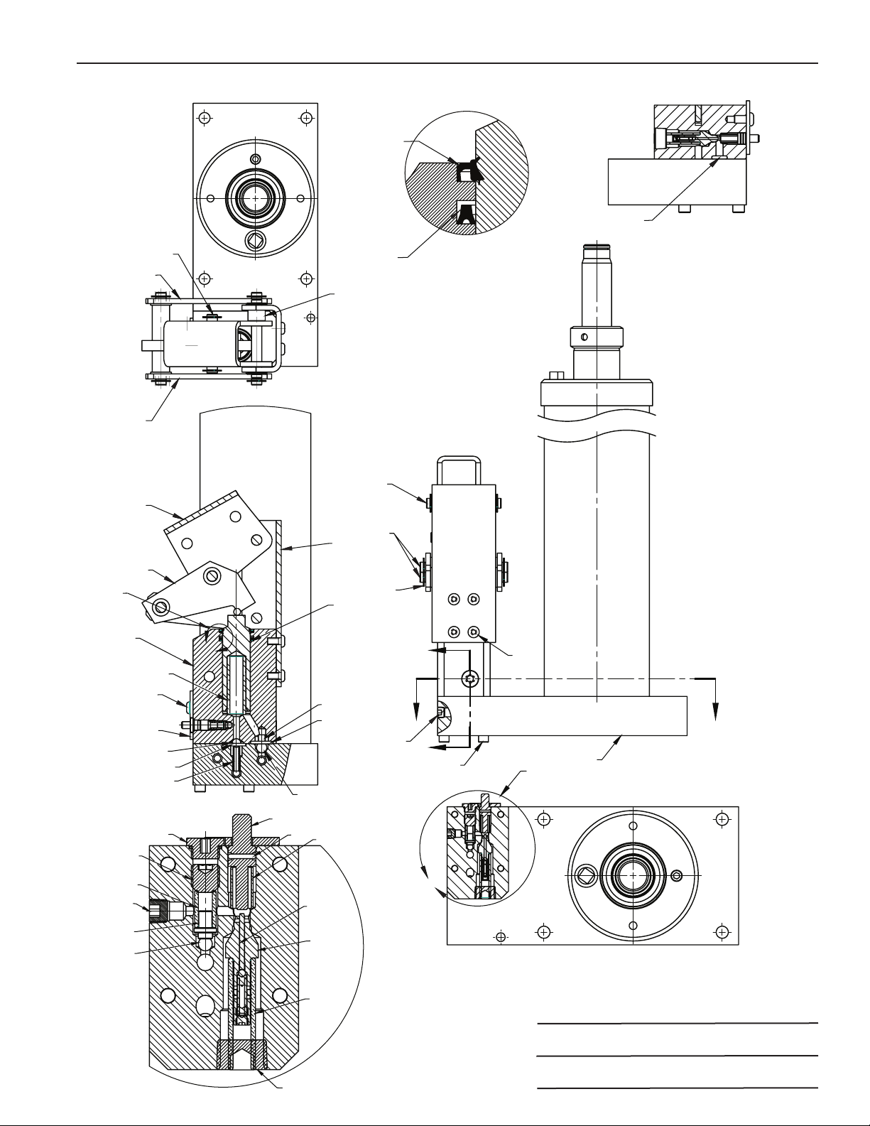
Jack Assembly
1
1
3
4
5
6
7
Detail W Section Y-Y
8
9
Y
Y
ZZ
10
11
12
13
14
15
16
17
18
19
20
21
22
W
23
24
25
See
Detail W
26
27
23
5 of 6
Detail X
28
29
30
31
32
33
34
35 36
37
38
39
40
Section Z-Z
See
Detail X
X
Parts List & Operating Instructions Form No. 560935, Sheet 5 of 6, Back
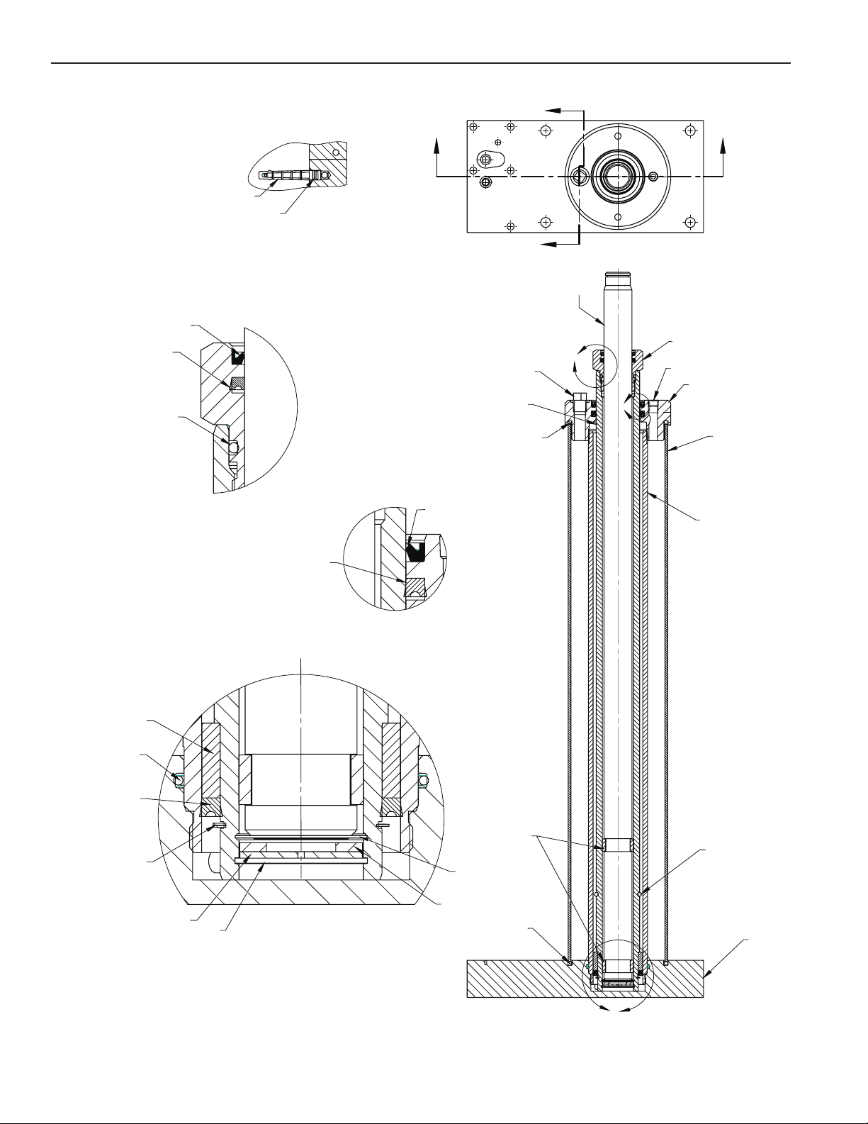
Cylinder Assembly
Detail Y
Detail Z
Detail X
SECTION V-V
SECTION W-W
X
WW
V
V
41
42
43
44
45
46
47
48
49
50
51
52 53
54
55
56
57
67
66
65
64
63
62
61
56
58
59
60
Y
Z
See
Detail Z
See
Detail Y
See
Detail X
Table of contents
Other OTC Jack manuals


Popular Jack manuals by other brands

Omega Lift Equipment
Omega Lift Equipment 18122C Operating instructions & parts manual

Pittsburgh
Pittsburgh 58816 Owner's manual & safety instructions

Unimec
Unimec TP Assembly instructions

Sonic
Sonic 4800703 instructions

BGS technic
BGS technic 70039 instruction manual

TradeQuip
TradeQuip 1128T owner's manual

VEVOR
VEVOR TJD-12000SP-F quick start guide

ULTIMATE SPEED
ULTIMATE SPEED URW 2 A1 HYDRAULIC TROLLEY JACK operating instructions

Stels
Stels 51131 user manual

Bushranger
Bushranger RJX01 instruction manual

Clarke
Clarke CTJ2500QLG Operating & maintenance instructions

Valex
Valex 1650520 Translation of the original instructions


