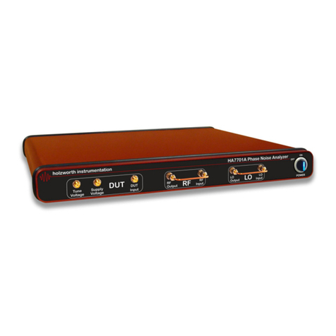
Holzworth Instrumentation HA7402B User manual

HA7402B
PHASE NOISE
ANALYZER
User Manual 1.04
Holzworth Instrumentation Inc.
1722 14th Street, Suite 220
Boulder, CO 80302 USA
R
oHS


HA7402B Manual Rev 1.04 www.holzworth.com Page 1 of 44
INDEX
INDEX...................................................................................................................................1
1.0 INTRODUCTION ...........................................................................................................3
2.0 CERTIFICATIONS and EXEMPTIONS.........................................................................3
2.1 CE CERTIFICATION...................................................................................................3
2.2 RoHS COMPLIANCE..................................................................................................3
3.0 PRODUCT WARRANTY ...............................................................................................3
4.0 CALIBRATION NOTICE................................................................................................3
5.0 HA7402B CONFIGURATION GUIDE............................................................................4
5.1 CONFIGURATION SUMMARY...................................................................................4
5.2 MECHANICAL CONFIGURATION.............................................................................5
5.2.1 Product Dimensions.............................................................................................5
5.2.2 Front Panel Connectors.......................................................................................6
5.2.3 Rear Panel Connectors .......................................................................................6
5.2.4 Operational Environment.....................................................................................7
5.2.5 Available Options & Accessories.........................................................................7
6.0 PERFORMANCE SUMMARY .......................................................................................8
6.1 RF INPUT...................................................................................................................8
6.2 PHASE NOISE MEASUREMENTS............................................................................8
6.3 PHASE NOISE MEASUREMENT SPEED (SAMPLE TIME)......................................9
6.4 x CORRELATIONS vs. PHASE NOISE IMPROVEMENT..........................................9
6.5 INTERNAL TIME BASE .............................................................................................9
6.6 LO MODES ................................................................................................................9
6.7 SSB PHASE NOISE SENSITIVITY - STANDARD...................................................10
6.8 SSB PHASE NOISE SENSITIVITY – OPTION OPT-PD1........................................11
7.0 PHASE NOISE ANALYZER INSTALLATION.............................................................12
7.1 APPLICATION GUI INSTALLATION........................................................................12
7.1.1 Minimum System Requirements........................................................................12
7.1.2 Downloading Java™..........................................................................................12
7.1.3 Loading the Application GUI..............................................................................13
7.1.4 Initializing the Application GUI...........................................................................13

HA7402B Manual Rev 1.04 www.holzworth.com Page 2 of 44
7.2 HARDWARE INSTALLATION..................................................................................14
7.2.1 Powering Analyzer with a 12V Battery...............................................................14
7.2.2 USB Hardware....................................................................................................14
7.2.3 Ethernet Hardware (Optional).............................................................................15
7.3 DEVICE CONNECTION...........................................................................................16
8.0 APPLICATION GUI / OPERATION.............................................................................17
8.1 MEASUREMENT DASHBOARD .............................................................................17
8.2 MEASUREMENT SETTINGS SUB-MENU.............................................................18
8.3 DISPLAY SETTINGS SUB-MENU.........................................................................22
8.4 SAVE / RECALL SUB-MENU..................................................................................27
8.4.1 Saving Data.......................................................................................................27
8.4.2 Saving the Debug file.........................................................................................28
8.4.3 Display Traces...................................................................................................28
8.4.4 Settings Save / Recall........................................................................................29
8.5 DISPLAY DATA ZOOM............................................................................................30
9.0 CONTACT INFORMATION.........................................................................................31
APPENDIX A:.....................................................................................................................32
EXTERNAL LO MODE - ABSOLUTE MEASUREMENT EXAMPLE...............................32

HA7402B Manual Rev 1.04 www.holzworth.com Page 3 of 44
1.0 INTRODUCTION
Thank you for purchasing a Holzworth Instrumentation HA7402B Phase Noise Analyzer. This user
manual is setup to cover specifications, product configuration, operational features and examples of
some common phase noise measurement applications as they relate to the analyzer.
2.0 CERTIFICATIONS and EXEMPTIONS
2.1 CE CERTIFICATION
Holzworth analyzer products comply by test and design, with the essential
requirements and other relevant provisions of the EMC Directive: 2004/108/EC,
and the Electrical equipment for measurement, control and laboratory use EMC
requirements (test standard): EN 61326-1: 2006;as set forth by the Council of
the European Union.
2.2 RoHS COMPLIANCE
Holzworth phase noise analyzer products are in compliance with Directive 2002/95/EC of the
European Parliament and of the Council of 27 January 2003 on the Restriction and use of Certain
Hazardous Substances in Electrical and Electronic Equipment (RoHS Directive), with an exemption
for Lead in Electronic Ceramic Parts (e.g. Piezoelectronic Devices) per the Directive’s Annex
Paragraph 7 applied.
3.0 PRODUCT WARRANTY
Holzworth analyzers come with a 2 year 100% product warranty covering manufacturing defects.
All product repairs and maintenance must be performed by Holzworth Instrumentation Inc.
Holzworth reserves the right to invalidate the warranty for any products that have been tampered
with or subjected to improper use. If the unit becomes damaged, please contact Holzworth
Instruments or your local representative for an RMA Number & instructions prior to returning the
unit for repair.
4.0 CALIBRATION NOTICE
Holzworth calibrates each phase noise analyzer product to be NIST traceable per the ANSI Z540
standard. The factory calibration is valid for 2 years from the original calibration date. Note the
calibration date on the calibration certificate shipped with each analyzer unit.
Contact sales@holzworth.com with model number and serial number for a calibration service
quotation. Holzworth also makes the calibration routine and equipment list available to customers
who have the capability to perform on site calibration. Contact support@holzworth.com for more
information.

HA7402B Manual Rev 1.04 www.holzworth.com Page 4 of 44
5.0 HA7402B CONFIGURATION GUIDE
5.1 CONFIGURATION SUMMARY
The HA7402B tunable phase noise analyzer responds to industry demands for a no frills phase
noise measurement system that is highly reliable and intuitive while offering measurement
speeds that eliminate bottlenecks on manufacturing test lines. The HA7402B is also an
incredibly cost effective solution for R&D, offering measurement floors below -190dBc/Hz.
The core engine combines the
best of traditional analog phase
noise measurement front-ends
(being virtually spur free) with the
latest technology in cross
correlation analysis. The digital
analysis system leverages a
proprietary DSP with a powerful
cross correlation engine.
The unparalleled stability of the
HA7402B is credited to a pair of
Holzworth HSM Series RF
Synthesizer modules. Holzworth
RF synthesizers are known for
industry leading stability due to
the proprietary non-PLL
architecture. These high
performing RF sources
compliment the dual core engine
to provide the most advanced
phase noise analyzer available.
Phase noise measurements do not benefit from modular analyzer architectures. Holzworth’s
fully shielded, fan-less 1U chassis completely eliminates ground loops and troublesome
microphonics for uncompromising performance when compared to traditional “rack and stack”
type systems.

HA7402B Manual Rev 1.04 www.holzworth.com Page 5 of 44
5.2 MECHANICAL CONFIGURATION
5.2.1 Product Dimensions
The HA7000 Series analyzers each come in a 1U high, rack mountable chassis. A universal rack
mount bracket kit is an available accessory (Part No.: RACK-1U or RACK2-1U). Mechanical
dimensions are listed in inches (and millimeters).
1.75
(45)
15.00
(381)
17.00
(432
)
TOP
REAR
FRONT
HA7402B

HA7402B Manual Rev 1.04 www.holzworth.com Page 6 of 44
5.2.2 Front Panel Connectors
DESCRIPTION SPECIFICATION
DUT Input
Connector Type
Frequency Range (standard)
Frequency Range (OPT-PD1)
Power Level Range
SMA (3.5mm), 50ohm
10MHz to 6.4GHz
10MHz to 1.5GHz with low noise front end option installed (OPT-PD1)
0dBm to +20dBm
DUT Tune Voltage
Connector Type
Voltage Tune Range
SMA (3.5mm), 50ohm
-10V to +10V
LO1 Input
Connector Type
Frequency Range (standard)
Frequency Range (OPT-PD1)
Power Level (optimal)
SMA (3.5mm), 50ohm
10MHz to 6.4GHz
10MHz to 1.5GHz with low noise front end option installed (OPT-PD1)
+10dBm
LO1 Tune Voltage
Connector Type
Voltage Tune Range
SMA (3.5mm), 50ohm
-10V to +10V
LO2 Input
Connector Type
Frequency Range (standard)
Frequency Range (OPT-PD1)
Power Level (optimal)
SMA (3.5mm), 50ohm
10MHz to 6.4GHz
10MHz to 1.5GHz with low noise front end option installed (OPT-PD1)
+10dBm
LO2 Tune Voltage
Connector Type
Voltage Tune Range
SMA (3.5mm), 50ohm
-10V to +10V
5.2.3 Rear Panel Connectors
DESCRIPTION SPECIFICATION
Reference Output Port
Connector Type
Output Frequency
Output Level
Output Waveform
SMA, 50ohm
10MHz ±10Hz
+4dBm ±3dBm
Sinusoid
Reference Input Port
Connector Type
Input Frequency
Input Level
ONLY FOR FREQUENCY COUNTERS - DOES NOT AFFECT MEASUREMENT SENSITIVITY
SMA, 50ohm
10MHz ±10Hz
0dBm to +10dBm (Sinusoid or Square)
DC Power Input
Connector Type
DC Voltage
AC/DC Power Adapter (included)
DC Input - Jack (Male)
12VDC -0.5VDC / +1.5VDC
100-240VAC, 47-63Hz. Output: 12VDC, 5ADC. Specify country at time of order. NO GROUND.
Data I/O Interface
Connector Type
Notes
DB25 (female)
For use with HCM5 Ethernet Communications Module

HA7402B Manual Rev 1.04 www.holzworth.com Page 7 of 44
5.2.4 Operational Environment
DESCRIPTION SPECIFICATION
Operating Environment
Temperature
Humidity
Altitude
Vibration
+10C to +40C
RH 20% to 80% at wet bulb temp. <29C (non-condensing)
0 to 2,000m (0 to 6,561 feet)
0.21 G-rms maximum, 5Hz to 500Hz
Storage (Non-Operating)
Temperature
Humidity
Altitude
Vibration
-10C to + 60C
RH 20% to 80% at wet bulb temp. <40C (non-condensing)
0 to 4,572m (0 to 15,000 feet)
0.5 G-rms maximum, 5Hz to 500Hz
5.2.5 Available Options & Accessories
Holzworth offers options and accessories to optimize the analyzer for an intended application.
Specify all required options and/or accessories when requesting a quotation or placing a purchase
order.
PART No. DESCRIPTION CLASSIFICATION
OPT-COMM Custom communications configuration OPTION
OPT-FIRM Custom firmware – Application specific OPTION
OPT-PD1 Low Noise Front End. 10dB improved noise floor in External LO Mode. 5MHz-1.5GHz. OPTION
HCM5 Add on Ethernet communications module for HA7000 Series. ACCESSORY
RACK-1U 19” Rack mount bracket kit for HA7000 Series. 90º rear. ACCESSORY
RACK2-1U 19” Rack mount bracket kit for HA7000 Series. Straight rear. ACCESSORY
CASE ACCESSORY

HA7402B Manual Rev 1.04 www.holzworth.com Page 8 of 44
6.0 PERFORMANCE SUMMARY
The HA7402A is designed for high speed and precise phase noise measurements. The
specifications outlined here capture the baseline performance and features that are currently
available from the HA7402A phase noise analyzer. The highly reliable hardware is capable of
additional functionality for custom requirements. Inquire with Holzworth Instrumentation or your
local sales representative.
6.1 RF INPUT
DESCRIPTION SPECIFICATION
RF Input Connector SMA (female), 50 ohm
RF Input Frequency Range 10 MHz to 6.4 GHz (standard front end)
10 MHz to 1.5GHz (low noise front end –option OPT-PD1)
RF Input Measurement Level 0 dBm to +20 dBm
Input Damage Level +22 dBm
Input VSWR < 2.0:1
6.2 PHASE NOISE MEASUREMENTS
DESCRIPTION SPECIFICATION
RF Input Frequency Range 10 MHz to 6.4 GHz (standard front end)
10 MHz to 1.5GHz (low noise front end –option OPT-PD1)
RF Tracking Range ± 100 kHz (offset dependent)
Measurement Parameters SSB Phase Noise
Number of Traces 1 measurement, 3 memory
Offset Frequency Range 1 Hz – 1 MHz
Phase Noise Uncertainty
1 Hz to 1 kHz offset
1 kHz to 1 MHz offset
± 4 dB
± 2 dB
SSB Phase Noise Sensitivity See pages 5-6
Measurement (Sample) Time See Table 1

HA7402B Manual Rev 1.04 www.holzworth.com Page 9 of 44
6.3 PHASE NOISE MEASUREMENT SPEED (SAMPLE TIME)
Frequency Offset Range Sample Time No. of Points Transfer Time (full) Transfer Time (point)
10kHz – 1MHz 20 ms 737 ~ 737 ms 4 ms
1kHz – 1MHz 54 ms 1102 ~ 1102 ms 4 ms
100Hz – 1MHz 420 ms 1467 ~ 1467 ms 4 ms
10Hz – 1MHz 3.2 s 1830 ~ 1830 ms 4 ms
1Hz – 1MHz 22 s 2192 ~ 2192 ms 4 ms
6.4 x CORRELATIONS vs. PHASE NOISE IMPROVEMENT
Improvement factor: dB = 5logN (N = No. of correlations)
Number of Correlations 1 10 100 1,000 10,000
dB Improvement 0dB 5dB 10dB 15dB 20dB
6.5 INTERNAL TIME BASE
DESCRIPTION SPECIFICATION
Frequency Uncertainty / Stability < ± 10Hz at 100MHz (±100 ppb) At time of shipment. Factory calibrated at +21C.
Frequency Temperature Effects < 10ppb
Frequency Aging Rate < 100ppb/yr
10MHz External Lock Range ± 2ppm (typical), ± 1ppm (specified). 10MHz is for frequency counters only.
6.6 LO MODES
MODE DESCRIPTION
External LO Mode User supplied LO sources. Auto calibration of LO sources and auto phase lock.

HA7402B Manual Rev 1.04 www.holzworth.com Page 10 of 44
6.7 SSB PHASE NOISE SENSITIVITY - STANDARD
STANDARD MIXERS
The Phase Noise Sensitivity of the analyzer is a combination of the quality of the external LO test
sources, the phase detectors (mixers) at the analyzer’s front end, and the sampling bandwidth that
is set via the low frequency offset (measurement start frequency).
External LO Mode allows the user to connect a pair of similar, non-coherent, external LO sources
that must match or exceed the phase noise performance of the DUT for achieving the fastest
measurement speeds and lowest noise floors. The system includes an auto-calibration function,
which characterizes the voltage tuning constant for each independent LO prior to each
measurement.
The sensitivity values outlined in this section are based on a single cross correlation. Lower phase
noise measurement floors are achieved by running additional cross correlations, as outlined in
section 6.4.
External LO Mode – Phase Detector Sensitivity

HA7402B Manual Rev 1.04 www.holzworth.com Page 11 of 44
6.8 SSB PHASE NOISE SENSITIVITY – OPTION OPT-PD1
OPTION: OPT-PD1 LOW NOISE MIXERS
The Low Noise Front End option (OPT-PD1) is offered for those applications which require the
ultimate combination of fast measurement speed with the lowest possible noise floor. Option OPT-
PD1 replaces the standard front end phase detectors with mixers that have been optimized over a
narrower bandwidth for increased sensitivity, ultimately providing the lowest possible measurement
floors.
The sensitivity values outlined in this section are based on a single cross correlation. Lower
phase noise measurement floors are achieved by running additional cross correlations, as outlined
in section 6.4.
NOTE: Installation of OPT-PD1 limits the operating frequency range of the entire instrument from
5MHz to 1.5GHz.
Phase Detector Sensitivity – Low Noise Front End

HA7402B Manual Rev 1.04 www.holzworth.com Page 12 of 44
7.0 PHASE NOISE ANALYZER INSTALLATION
This section outlines the basic installation requirements and procedures for the HA7000
Series Phase Noise Analyzer application GUI and the hardware.
First, the application GUI software must be installed. The GUI software is contained on the
CD that was included with the analyzer module. If the CD is missing another can be
emailed or the software can be downloaded after contacting Holzworth support via email at:
support@holzworth.com or by phone at +1.303.325.3473 (option 2).
7.1 APPLICATION GUI INSTALLATION
Holzworth analyzers are PC controlled Instruments (virtual front panel) that interface with a
PC via USB as a Human Interface Device (HID).
The application GUI software is Java™ based, requiring no driver installation. A single DLL
file transfers high level language commands to USB level or Ethernet compatible
instructions.
Java™ must be installed on the command PC in order to run the application GUI.
7.1.1 Minimum System Requirements
DESCRIPTION SPECIFICATION
Minimum System Requirements Pentium 4, 512MB RAM, USB 2.0
Operating System Windows XP, 2000, 2003 Server, Vista, 7, 8 / Java 6.0 installed
Minimum Display Resolution 900 x 500 pixels
Touch Screen Compatible Yes
7.1.2 Downloading Java™
Holzworth utilizes a Java™ based platform for development of the
“HolzworthPNA” application because of its high reliability. Java™ is
freeware. The latest version of Java™ can be downloaded directly from
Oracle.
To validate what version of Java™ is installed on the host PC or to download the latest
version, go to:
http://www.java.com/en/download/index.jsp

HA7402B Manual Rev 1.04 www.holzworth.com Page 13 of 44
7.1.3 Loading the Application GUI
The CD included with the analyzer contains an application file folder with 2 files that
include: a .dll file, a .jar file. Make sure both files remain inside the original folder
location.
7.1.4 Initializing the Application GUI
The phase noise analyzer application does not utilize the Windows software Installation
Wizard. The following 2 steps need occur to launch the application:
1. Save the entire folder to a preferred directory on the PC or portable
memory device. Be certain that the entire folder has been extracted.
2. Double click the “HolzworthPNA.jar” Executable Jar File to open the
application. The GUI will be immediately displayed on the monitor.
Analyzer GUI
Application Folder

HA7402B Manual Rev 1.04 www.holzworth.com Page 14 of 44
7.2 HARDWARE INSTALLATION
Prior to initializing the analyzer, connect the external power
supply to the rear panel connector and an AC outlet. The
instrument is shipped with the appropriate power cord for the
final destination country/region.
The master power switch located at the right side of the front
panel is equipped with a blue indicator light which illuminates
when the DC power is active.
7.2.1 Powering Analyzer with a 12V Battery
The HA7000 Series has been designed with an external power supply to support clean,
ultra low phase noise measurements. However, a battery is the absolute cleanest supply
voltage for powering a DUT, external LOs (when used) and even the phase noise analyzer.
The rear panel is equipped with a vertical row of LED indicators that are used to monitor
the DC input voltage range.
LED (top to bottom) Indication
Yellow Voltage high. >13.5VDC
Green Voltage in range. 11.5-13.5VDC
Yellow Voltage low. <11.5VDC
Red Voltage out of range. Reverse polarity.
NOTE: The internal voltage regulator has built in, auto-resetting circuit protection.
7.2.2 USB Hardware
A USB 2.0 port is built into the front panel of
the instrument, located to the immediate left
side of the master power switch. The analyzer
is an HID (Human Interface Device) that is
recognized by the PC via standard Windows
drivers. With the application folder installed
on the PC and the GUI launched, the
analyzer can now be connected via the
provided USB cable.
A proprietary 10ft (3m) USB 2.0 cable is provided with the instrument. If lost, a standard
USB 2.0 cable with a type A connector at the PC, and a mini-B connector at the analyzer
can be utilized in its place. The cable that is included with the equipment has a proprietary
end fitting that enables secure fastening at the analyzer via 2 captive panel screws (as
pictured above).

HA7402B Manual Rev 1.04 www.holzworth.com Page 15 of 44
7.2.3 Ethernet Hardware (Optional)
An Ethernet connection is available via the back panel of the instrument using part number:
HCM5 (USB Communication Module for HA7000 Series). The HCM5 module comes with a
standard 10ft (3m) CAT-6 Ethernet cable.
The HCM5 is installed directly to the DB25 connector located at the left side of the rear
panel, using the 2x captive panel screws to securely fasten the HCM5 into position. Once
the HCM5 is installed, an Ethernet cable can be used to connect the instrument directly to
a PC or to a network.
NOTE 1: USB INACTIVATED. Once the HCM5 module is physically mated to the
synthesizer, USB control will no longer be available to the user. This scenario is
valid whether or not an Ethernet cable is installed. To regain a USB connection, the
HCM5 module must be completely removed from the instrument.
NOTE 2: For direct PC connection via Ethernet (non-networked) a cross over
Ethernet cable is required.

HA7402B Manual Rev 1.04 www.holzworth.com Page 16 of 44
7.3 DEVICE CONNECTION
To locate and connect to the device, press the button
labeled: No Device Attached. This button is located at the
upper left area of the GUI window, immediately below the
green Acquire button.
Depressing the No Device Attached button initiates the
Devices popup window which lists all Holzworth phase
noise analyzer devices that are connected to the PC,
including demo mode (HA7062B-DEMO).
NOTE that the firewall for 64 bit Windows machines may
attempt to block access to this function. In the Windows
Security Alert window, select the Allow access button to
proceed.
Select the unit to be controlled by the GUI. If multiple
devices are connected and to be controlled, the user must
initiate separate instances of the GUI and designate each
instance to a separate available unit.
The device name protocol is by part number, followed by
serial number. The unique part number/serial number can
be found at the rear and/or front panel of the hardware.
The selected device’s unique identifier (part number / serial number) will replace the “No
Device Attached” message inside the button, as shown in the diagram above.
NOTE that the GUI is universal for Holzworth phase noise analyzer
products. GUI functionality will automatically update to appropriately
match the capabilities of the selected /attached device.

HA7402B Manual Rev 1.04 www.holzworth.com Page 17 of 44
8.0 APPLICATION GUI / OPERATION
The application GUI is opened by double clicking on the “HolzworthPNA.jar” executable file.
This section defines the basic operation of the standard application GUI that is provided for
the phase noise analyzer platform. If the Holzworth was ordered with the OPT-FIRM
option, then a separate document will have been supplied, which outlines the operation of
the custom application GUI.
8.1 MEASUREMENT DASHBOARD
The measurement dashboard contains the data display, status indicators and is the access
portal to all of the analyzer settings.
8.1.1 Keyboard and Mouse Functions
As a virtual instrument, the PC keyboard and mouse functions are intuitively integrated for
ease of operation.
KEY
FUNCTION
Tab
used to move the Highlighted Field indicator from left to right
Left/Right Arrows
used to move the Highlighted Field both left and right
Up/Down Arrows
used to increase/decrease the value of the Highlighted Field
Number Ke
ys
used to directly enter value into active field
Data Plot Area
Connect Device
Used to locate and connect to
an analyzer attached to PC.
Also serves as indicator of what
serialized device is connected.
Status Indicator Light
Measurement Settings
Initializes measurement
settings sub-menu.
STOP
button
cancels
data acquisition session.
Acquire
button
initiates
data acquisition session.
Scrolling Status Log
Maintains session data from
power on. Used as historical
reference and/or debug file for
factory support.
Display Settings
Initializes display settings
sub-menu.
Save / Recall
Open sub-menu for saving
data, recalling historical data,
and recalling user settings.
Status
Tracks completed No. of
correlations, elapsed time
and status of DUT
Markers
Data Title

HA7402B Manual Rev 1.04 www.holzworth.com Page 18 of 44
8.2 MEASUREMENT SETTINGS SUB-MENU
The Measurement button provides access to the
measurement settings sub-menu. The functions available in
this sub-menu allow for: setting the frequency offset range of
the measurement, and the number of correlations (either for the entire band or
independently for specific bands).
This submenu also contains the INPUT control panel for checking DUT status, and setting
up the calibration files for the external LOs. A specific example of external LO calibration is
provided in Appendix A.
Frequency Offset
Adjust close to the carrier
offset range.
Number of Correlations
Set number of correlations
for the entire range or chose
“banded” option.
Frequency Counter Precision
Set number of intervals for
frequency counter to detect DUT
frequency. Trade speed for
precision.
DUT Status Verification
Quick check for frequency and
power level of the DUT. Manual
setting for DUT tune voltage.
Set LO Tune Voltages
External LO tune voltage
range is independently
settable for each LO
LO Calibration S
ub
-
menu
Accesses the LO calibration table to
verify calibrated range of each LO.
Advanced Measurement Settings Sub
-
menu
Accesses PLL correction controls, measurement
type, and Gain settings.
Engine Mode
Set for running XCorr test or
validating performance of each (or
both) external LO.
This manual suits for next models
1
Table of contents
Other Holzworth Instrumentation Measuring Instrument manuals
Popular Measuring Instrument manuals by other brands

Schneider Airsystems
Schneider Airsystems RF-RM geeicht Original operating manual

Elcometer
Elcometer 223 operating instructions

Agilent Technologies
Agilent Technologies FieldFox N9912A user guide

Greyline Instruments
Greyline Instruments DFM 5.0 user guide

Anritsu
Anritsu MS2711A user guide

Extech Instruments
Extech Instruments LT300 user guide