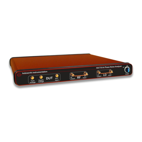
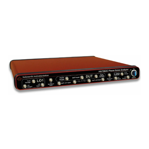
Holzworth Instrumentation HA7062D User manual

HA7062D
PHASE NOISE
ANALYZER
User Manual 1.01
Holzworth Instrumentation Inc.
2540 Frontier Ave., Suite 200
Boulder, CO 80301 USA
www.holzworth.com
RoHS

This page intentionally left blank.

HA7062D Manual Rev 1.01 www.holzworth.com Page 1 of 105
ATTENTION
HOT SURFACES
Steady state operating conditions can result in surface
temperatures that exceed 60C and the unit will be hot
to the touch. This is normal operation.
The HA7062D Real Time Phase Noise Analyzer is a fanless chassis
design. Internal conductive heat dissipation assists with measurement
repeatability and accuracy while eliminating microphonics caused by
chassis cooling fans.
When installing the unit into populated communications racks it is
recommended that rack cooling fans be used to eliminate thermal run
away, which may result in measurement errors and/or system warnings.
ATTENTION
HOT SURFACES

HA7062D Manual Rev 1.01 www.holzworth.com Page 2 of 105
Table of Contents
1.0 INTRODUCTION ...................................................................................................................... 5
2.0 CERTIFICATIONS and EXEMPTIONS .................................................................................... 5
2.1 CE CERTIFICATION.............................................................................................................5
2.2 RoHS COMPLIANCE............................................................................................................5
3.0 PRODUCT WARRANTY .......................................................................................................... 5
4.0 CALIBRATION NOTICE........................................................................................................... 5
5.0 TECHNICAL SUPPORT........................................................................................................... 5
6.0 HA7062D CONFIGURATION SUMMARY................................................................................ 6
6.1 MECHANICAL CONFIGURATION & ACCESSORIES......................................................... 7
6.1.1 PRODUCT DIMENSIONS..............................................................................................7
6.1.2 FRONT PANEL CONNECTORS.................................................................................... 8
6.1.3 REAR PANEL CONNECTORS ...................................................................................... 9
6.1.4 OPERATIONAL ENVIRONMENT................................................................................... 9
6.1.5 AVAILABLE OPTIONS & ACCESSORIES................................................................... 10
6.1.6 INCLUDED HARDWARE AND CERTIFICATIONS ...................................................... 10
7.0 PERFORMANCE SUMMARY................................................................................................. 11
7.1 RF INPUT........................................................................................................................... 11
7.2 PHASE NOISE MEASUREMENTS..................................................................................... 11
7.3 MEASUREMENT SPEED (SAMPLE TIME) vs. MINIMUM OFFSET................................... 12
7.4 xCORRELATIONS vs. PHASE NOISE IMPROVEMENT .................................................... 12
7.5 CROSS CORRELATIONS (AVERAGES) vs. FREQUENCY OFFSET................................. 13
7.6 INTERNAL TIME BASE...................................................................................................... 13
7.7 MEASUREMENT MODES.................................................................................................. 13
7.8 INSTRUMENT NOISE FLOOR........................................................................................... 14
7.9 CROSS CORRELATION SNR (xCorr SNR)........................................................................ 18
7.9.1 INSTRUMENT NOISE FLOOR vs. xCORR SNR........................................................... 18
8.0 PHASE NOISE ANALYZER INSTALLATION ........................................................................ 19
8.1 HARDWARE INSTALLATION............................................................................................. 19
8.2 INSTRUMENT COMMUNICATION..................................................................................... 19
9.0 HOLZWORTH PNA SOFTWARE APPLICATION.................................................................. 20
9.1 GUI OVERVIEW.................................................................................................................. 21
9.2 USB, RS-232, AND GPIB COMMUNICATION..................................................................... 23
9.2.1 IDENTIFY INSTRUMENT COM PORT & USB TROUBLESHOOTING.......................... 24
9.2.2 GPIB COMMUNICATION.............................................................................................. 25
9.3 ETHERNET COMMUNICATION.......................................................................................... 26
9.3.1 LAN CONNECTION...................................................................................................... 26
9.3.2 DIRECT PC CONNECTION (DHCP)............................................................................. 27
9.3.3 ASSIGNING A STATIC IP ADDRESS........................................................................... 28

HA7062D Manual Rev 1.01 www.holzworth.com Page 3 of 105
9.4 TROUBLESHOOTING ETHERNET CONNECTIONS.......................................................... 30
9.4.1 ETHERNET RESET VIA USB & APPLICATION GUI.................................................... 30
9.4.2 MISCELLANEOUS ETHERNET TROUBLESHOOTING STEPS................................... 31
9.5 SOFTWARE UPDATES....................................................................................................... 33
9.6 FIRMWARE UPDATES........................................................................................................ 33
9.7 MEASUREMENT................................................................................................................. 34
9.7.1 MEASUREMENT SETUP.............................................................................................. 34
9.7.2 FREQUENCY SPAN (MEASUREMENT OFFSET & INTEGRATION LIMITS)............... 35
9.7.3 TRIGGER/AVERAGING/BANDWIDTH ......................................................................... 36
9.7.4 ADVANCED SETTINGS................................................................................................ 37
9.8 INPUTS ............................................................................................................................... 38
9.8.1 DUT INPUTS................................................................................................................. 38
9.8.2 LO INPUTS................................................................................................................... 40
9.8.3 DUT TEST & LO TEST.................................................................................................. 41
9.9 OUTPUTS............................................................................................................................ 42
9.9.1 DUT SUPPLY OUTPUTS.............................................................................................. 42
9.9.2 DUT TUNE OUTPUT .................................................................................................... 42
9.9.3 LO SOURCE OUTPUTS............................................................................................... 43
9.9.4 LO TUNE OUTPUTS..................................................................................................... 43
9.10 ACQUIRING DATA............................................................................................................ 44
9.11 TRACE/CALCS.................................................................................................................. 44
9.11.1 SMOOTHING.............................................................................................................. 45
9.11.2 SPUR DISPLAY.......................................................................................................... 45
9.11.3 RIGHT CLICK FUNCTIONS........................................................................................ 46
9.12 MARKERS......................................................................................................................... 47
9.12.1 DECADE MARKERS................................................................................................... 47
9.12.2 USER MARKERS........................................................................................................ 48
9.13 LIMITS............................................................................................................................... 49
9.13.1 LIMIT LINE SETUP..................................................................................................... 49
9.14 DISPLAY............................................................................................................................ 50
9.14.1 PLOT DISPLAY RANGES........................................................................................... 50
9.14.2 PLOT DISPLAY OPTIONS.......................................................................................... 51
9.14.3 PLOT DISPLAY LABELS ............................................................................................ 51
9.14.4 MISCELLANEOUS OPTIONS..................................................................................... 52
9.15 CONSOLE......................................................................................................................... 52
9.16 FILE MENU........................................................................................................................ 53
9.16.1 SAVE/LOAD DATA (HOLZWORTH TRACE FILE, .HTF)............................................ 53
9.16.2 IMPORT/EXPORT DATA (COMMA SEPARATED VALUE, .CSV) .............................. 53
9.16.3 GENERATE REPORT................................................................................................. 54
9.16.4 EXPORT PLOT AND PRINT....................................................................................... 54
9.17 TOOLS MENU................................................................................................................... 54

HA7062D Manual Rev 1.01 www.holzworth.com Page 4 of 105
9.18 SYSTEM MENU................................................................................................................. 55
9.18.1 SAVE/PRESET/LOAD INSTRUMENT SETTINGS...................................................... 55
9.18.2 VIEW DEBUG ............................................................................................................. 55
9.18.3 HX5100 CALIBRATION FILES.................................................................................... 55
9.18.4 UPDATE FIRMWARE ................................................................................................. 55
10.0 ERROR MESSAGES & TROUBLESHOOTING .................................................................... 56
11.0 MEASUREMENT EXAMPLES .............................................................................................. 60
11.1 ADDITIVE MEASUREMENTS (<6GHz)............................................................................. 60
11.1.1 ADDITIVE MEASUREMENTS USING MECHANICAL PHASE SHIFTERS................. 61
11.2.2 ADDITIVE MEASUREMENTS USING HX5100 PHASE SHIFTERS ............................... 64
11.3 SINGLE CH. ADDITIVE MEASUREMENT WITH EXTERNAL MIXER............................... 68
11.4 AM NOISE MEASUREMENTS .......................................................................................... 72
12.0 CONTACT INFORMATION .................................................................................................. 73
APPENDIX A: PROGRAMMING COMMANDS............................................................................. 74
APPENDIX B: ETHERNET CONFIGURATION COMMANDS..................................................... 100
APPENDIX C: GPIB CONFIGURATION COMMANDS............................................................... 103

HA7062D Manual Rev 1.01 www.holzworth.com Page 5 of 105
1.0 INTRODUCTION
Thank you for purchasing a Holzworth Instrumentation HA7062D Phase Noise Analyzer. This user
manual is setup to cover specifications, product configuration, operational features and examples of
some common phase noise measurement applications as they relate to the analyzer.
2.0 CERTIFICATIONS and EXEMPTIONS
2.1 CE CERTIFICATION
Holzworth analyzer products comply by test and design, with the essential
requirements and other relevant provisions of the EMC Directive: 2004/108/EC,
and the Electrical equipment for measurement, control and laboratory use EMC
requirements (test standard): EN 61326-1: 2006;as set forth by the Council of
the European Union.
2.2 RoHS COMPLIANCE
Holzworth phase noise analyzer products are in compliance with Directive 2002/95/EC of the
European Parliament and of the Council of 27 January 2003 on the Restriction and use of Certain
Hazardous Substances in Electrical and Electronic Equipment (RoHS Directive), with an exemption
for Lead in Electronic Ceramic Parts (e.g. Piezoelectronic Devices) per the Directive’s Annex
Paragraph 7 applied.
3.0 PRODUCT WARRANTY
Holzworth analyzers come with a 2 year 100% product warranty covering manufacturing defects.
All product repairs and maintenance must be performed by Holzworth Instrumentation Inc.
Holzworth reserves the right to invalidate the warranty for any products that have been tampered
with or subjected to improper use. If the unit becomes damaged, please contact Holzworth
Instruments or your local representative for an RMA Number & instructions prior to returning the
unit for repair.
4.0 CALIBRATION NOTICE
Holzworth calibrates each phase noise analyzer product to be NIST traceable per the ANSI Z540
standard. The factory calibration is valid for 2 years from the original calibration date. Note the
calibration date on the calibration certificate shipped with each analyzer unit.
Contact sales@holzworth.com with model number and serial number for a calibration service
quotation. Holzworth also makes the calibration routine and equipment list available to customers
who have the capability to perform on site calibration. Contact support@holzworth.com for more
information.
5.0 TECHNICAL SUPPORT
telephone at +1.303.325.3473 (option 2). For support regarding any measurement/software errors
or issues, please send a 'debug file' via email. Refer to section 8.16 to view/save a debug file.

HA7062D Manual Rev 1.01 www.holzworth.com Page 6 of 105
6.0 HA7062D CONFIGURATION SUMMARY
The HA7062D phase noise analyzer responds to industry demands for a no frills phase noise
measurement system that is highly reliable and intuitive while offering measurement speeds that
eliminate bottlenecks on manufacturing test lines. The HA7062D is also an incredibly cost effective
solution for R&D, offering measurement floors below -190dBc/Hz.
The core engine combines the best
of traditional analog phase noise
measurement front-ends (being
virtually spur free) with the latest
technology in cross correlation
analysis. The digital analysis
system leverages a proprietary
DSP with a powerful cross
correlation engine.
The unparalleled stability of the
HA7062D is credited to a pair of
Holzworth HSX Series RF
Synthesizer modules. These ultra
low noise RF sources compliment
the dual core engine to provide one
of the most advanced phase noise
analyzers available.
Phase noise measurements do not
benefit from modular analyzer
architectures. Holzworth’s fully
shielded, fan-less 1U chassis
completely eliminates ground loops
and troublesome microphonics for
uncompromising performance when
compared to traditional “rack and
stack” style systems.
The HA7062D was designed to be
used in a number of different
configurations to accommodate a
wide range of measurement modes:
1. Absolute measurements, Internal LO Mode ≤ 26GHz (optional to ≤40GHz) utilizes a pair of
integrated Holzworth HSX Series RF Synthesizers as the LO test sources.
2. Absolute measurements, External LO Mode which allows the user to apply high
performance external sources as the LOs.
3. Automated Additive measurements up to 6GHz using Holzworth HX5100 electronic phase
shifters.
4. Baseband Mode for direct access to the onboard FFT engine for additional functionality,
including additive phase noise measurements with external phase detectors and
measurements of DC supplies.

HA7062D Manual Rev 1.01 www.holzworth.com Page 7 of 105
6.1 MECHANICAL CONFIGURATION & ACCESSORIES
6.1.1 PRODUCT DIMENSIONS
The HA7000 Series analyzers each come in a 1U high, rack mountable chassis. A universal rack
mount bracket kit is an available accessory (Part No.: RACK-1U or RACK2-1U). Mechanical
dimensions are listed in inches (and millimeters).
15.00
(381)
17.00
(432)
TOP
1.75
(44.45)

HA7062D Manual Rev 1.01 www.holzworth.com Page 8 of 105
6.1.2 FRONT PANEL CONNECTORS
DESCRIPTION
SPECIFICATION
Front Panel Connector(s) Type
26GHz DUT Input (standard)
40GHz DUT Input (optional)
All other
3.5mm (50ohm)
2.92mm (50ohm)
3.5mm (50ohm)
DUT Input
26GHz Frequency Range (standard)
40GHz Frequency Range (optional)
Power Level Range
Input Damage Level
10MHz to 26GHz
10MHz to 40GHz
-5dBm to +20dBm
> +22dBm, >25Vdc
DUT Tune Voltage
Voltage Tune Range
Max Current
For Vcc control of some DUTs.
-10V to +12V
5mA
DUT Power Supply
Voltage Supply Range
Maximum Current
Integrated power supply.
0V to +12V
250mA
LO1/LO2 Input(s)
Frequency Range (standard)
Power Level Range
Input Damage Level
Connect to LO1/LO2 Output(s) for standard operation.
10MHz to 6GHz
+3dBm to +13dBm
> +22dBm
LO1/LO2 Output(s)
Frequency Range (standard)
Power Level Range
Connect to LO1/LO2 Input(s) for standard operation.
10MHz to 6GHz (0.001Hz step size)
0dBm to +10dBm (0.01dB step size)
LO1/LO2 Tune Voltage
Voltage Tune Range
Max Current
Tuning Sensitivity
For independent Vcc control of external LO sources during External LO Mode of operation.
-10V to +12V
5mA
TBD
DUT ch1/ch2 Input(s)
Frequency Range (standard)
Power Level Range
Input Damage Level
Allows bypass of DUT power splitter for direct access to the phase detector of each channel.
10MHz to 6GHz
0dBm to +14dBm
> +16dBm
ch1/ch2 Splitter Output(s)
Connect to DUT ch1/ch2 Inputs for standard operation.
ch1/ch2 Baseband Input(s)
Frequency Range
Power Level Range
Input Damage Level
DC to 100MHz
± 1Vdc
± 2Vdc, or 50mA (whichever is greater), +10dBm RF power

HA7062D Manual Rev 1.01 www.holzworth.com Page 9 of 105
6.1.3 REAR PANEL CONNECTORS
DESCRIPTION
SPECIFICATION
Reference Output Port
Connector Type
Output Frequency
Output Level
Output Waveform
SMA, 50ohm
10MHz ±10Hz
+5dBm ±2dBm
Sinusoid
Reference Input Port
Connector Type
Input Frequency
Input Level
ONLY FOR FREQUENCY COUNTERS - DOES NOT AFFECT MEASUREMENT SENSITIVITY
SMA, 50ohm
10MHz ±10Hz
0dBm to +10dBm (Sinusoid or Square)
AC Power Input
Connector Type
AC Input Rating
IEC 320-C13
100-240VAC, 47-63Hz. Specify country at time of order.
Data I/O Interface
Connectivity
Storage
USB B-Type (virtual COM port), Ethernet, RS-232, GPIB
SD Card Reader (not currently functional)
6.1.4 OPERATIONAL ENVIRONMENT
DESCRIPTION
SPECIFICATION
Operating Environment
Temperature
Humidity
Altitude
Vibration
+10C to +40C
RH 20% to 80% at wet bulb temp. <29C (non-condensing)
0 to 2,000m (0 to 6,561 feet)
0.21 G-rms maximum, 5Hz to 500Hz
Storage (Non-Operating)
Temperature
Humidity
Altitude Altitude
Vibration
-10C to + 60C
RH 20% to 80% at wet bulb temp. <40C (non-condensing)
0 to 4,572m (0 to 15,000 feet)
0.5 G-rms maximum, 5Hz to 500Hz

HA7062D Manual Rev 1.01 www.holzworth.com Page 10 of 105
6.1.5 AVAILABLE OPTIONS & ACCESSORIES
Holzworth offers options and accessories to optimize the analyzer for an intended application.
Specify all required options and/or accessories when requesting a quotation or placing a purchase
order.
PART No.
DESCRIPTION
CLASSIFICATION
OPT-CC40
Frequency extension enables measurements to 40GHz
OPTION
HX5100-x
Electronic Phase Shifter PAIR, Additive Measurements , 1 Octave Bandwidth, Specify fc
ACCESSORY
CASE-1U
Ruggedized Carrying Case with TSA security lock
ACCESSORY
RACK-1U
19” Rack mount bracket kit for HA7000 Series. 90 degree rear bracket.
ACCESSORY
RACK2-1U
19” Rack mount bracket kit for HA7000 Series. Straight rear bracket.
ACCESSORY
6.1.6 INCLUDED HARDWARE AND CERTIFICATIONS
Each standard product delivery includes specific, standard hardware and certifications.
TYPE
DESCRIPTION
COMMENTS
HARDWARE
HA7062D PHASE NOISE ANALYZER
DELIVERABLE
HARDWARE
AC Power Cord (7ft/2.1m). Specify country of end use.
DELIVERABLE
HARDWARE
Ethernet Cable (10ft/3m)
DELIVERABLE
HARDWARE
USB Cable (6ft/1.8m)
DELIVERABLE
CERTIFICATE
ANSI z540.1 CALIBRATION CERTIFICATE (1Hz - 100MHz)
DELIVERABLE
WARRANTY
3 YEAR MANUFACTURER’S WARRANTY
NON-APPLICABLE
CERTIFICATE
CE COMPLIANCE CERTIFICATE
DIRECTIVE: 2004/108/EC, TEST STANDARD: EN 61326-1: 2006
WEB DOWNLOAD
CERTIFICATE
RoHS COMPLIANCE CERTIFICATE
DIRECTIVE: 2002/95/EC
WEB DOWNLOAD
CERTIFICATE
WEEE COMPLIANCE STATEMENT
DIRECTIVE: 2002/96/EC
WEB DOWNLOAD

HA7062D Manual Rev 1.01 www.holzworth.com Page 11 of 105
7.0 PERFORMANCE SUMMARY
The HA7062D is designed for high speed and precise phase noise measurements. The
specifications outlined here capture the baseline performance and features that are currently
available from the HA7062D phase noise analyzer. The highly reliable hardware is capable of
additional functionality for custom requirements. Inquire with Holzworth Instrumentation or your
local sales representative.
7.1 RF INPUT
DESCRIPTION
SPECIFICATION
RF Input Connector
26GHz DUT Input (standard)
40GHz DUT Input (optional)
3.5mm (female), 50 ohm
2.92mm (female), 50 ohm
RF Input Frequency Range
26GHz DUT Input (standard)
40GHz DUT Input (optional)
10 MHz to 26 GHz
10 MHz to 40 GHz
RF Input Measurement Level
-5 dBm to +20 dBm
Input Damage Level
+22 dBm
Input VSWR
< 2.0:1
7.2 PHASE NOISE MEASUREMENTS
DESCRIPTION
SPECIFICATION
RF Input Frequency Range
10 MHz to 26 GHz
RF Frequency Extension
10MHz to 40GHz (with OPT-CC40)
RF Tracking Range
±10ppm (typical), ±5ppm (specified)
Measurement Parameters
SSB Phase Noise
Offset Frequency Range
1 Hz –100 MHz (Settable to 0.1Hz Offset)
Phase Noise Uncertainty
0.1 Hz to 1 kHz offset
1 kHz to 1 MHz offset
1MHz to 100MHz offset
± 4 dB (to be updated with improved uncertainty resulting from z540.1 calibration statistics)
± 2 dB (to be updated with improved uncertainty resulting from z540.1 calibration statistics)
Cross Correlation
See section 7.4
Measurement (Sample) Time
See Table 7.3

HA7062D Manual Rev 1.01 www.holzworth.com Page 12 of 105
7.3 MEASUREMENT SPEED (SAMPLE TIME) vs. MINIMUM OFFSET
NOTE: Measurement times shown below are total data acquisition time. Data acquisition time does
not include data transfer time to PC. Utilizing an Ethernet/LAN connection is recommended to best
take advantage of the data acquisition speed of the instrument.
1 Cross-Correlation
64 Samples
128 Samples
256 Samples
512 Samples
1024 Samples
-
-
-
-
0.1Hz
17s
0.1Hz
34s
0.1Hz
1m8s
1Hz
1.1s
1Hz
2.2s
1Hz
4.3s
1Hz
8.6s
1Hz
17s
10Hz
0.3s
10Hz
0.5s
10Hz
1.1s
10Hz
2.2s
10Hz
4.3s
100Hz
0.1s
100Hz
0.1s
100Hz
0.3s
100Hz
0.5s
100Hz
1.1s
1kHz
<0.1s
1kHz
<0.1s
1kHz
0.1s
1kHz
0.1s
1kHz
0.3s
10kHz
<0.1s
10kHz
<0.1s
10kHz
<0.1s
10kHz
<0.1s
10kHz
<0.1s
100kHz
<0.1s
100kHz
<0.1s
100kHz
<0.1s
100kHz
<0.1s
100kHz
<0.1s
1MHz
<0.1s
1MHz
<0.1s
1MHz
<0.1s
1MHz
<0.1s
1MHz
<0.1s
10 Cross-Correlations
64 Samples
128 Samples
256 Samples
512 Samples
1024 Samples
-
-
-
-
0.1Hz
2m51s
0.1Hz
5m42s
0.1Hz
11m24s
1Hz
11s
1Hz
21s
1Hz
43s
1Hz
1m25s
1Hz
2m51s
10Hz
2.7s
10Hz
5.4s
10Hz
11s
10Hz
22s
10Hz
43s
100Hz
0.7s
100Hz
1.3s
100Hz
2.7s
100Hz
5.4s
100Hz
11s
1kHz
0.2s
1kHz
0.3s
1kHz
0.7s
1kHz
1.3s
1kHz
2.7s
10kHz
<0.1s
10kHz
<0.1s
10kHz
0.1s
10kHz
0.2s
10kHz
0.3s
100kHz
<0.1s
100kHz
<0.1s
100kHz
<0.1s
100kHz
<0.1s
100kHz
<0.1s
1MHz
<0.1s
1MHz
<0.1s
1MHz
<0.1s
1MHz
<0.1s
1MHz
<0.1s
7.4 xCORRELATIONS vs. PHASE NOISE IMPROVEMENT
Improvement factor: dB = 5logN (N = No. of correlations)
Number of Correlations
1
10
100
1,000
10,000
dB Improvement
0dB
5dB
10dB
15dB
20dB

HA7062D Manual Rev 1.01 www.holzworth.com Page 13 of 105
7.5 CROSS CORRELATIONS (AVERAGES) vs. FREQUENCY OFFSET
Holzworth HA7062D Phase Noise Analyzers employ fully real time data acquisition across the
entire measurement bandwidth. Therefore it is only necessary to specify the number of cross
correlations for the frequency band which requires the greatest amount of physical measurement
time (i.e. the lowest frequency to be measured).
In the amount of time physically required to measure the lowest frequency the instrument will
automatically perform as many cross correlations as possible in every frequency band further from
the carrier with zero increase in measurement speed.
7.6 INTERNAL TIME BASE
DESCRIPTION
SPECIFICATION
Frequency Uncertainty / Stability
< ± 1Hz at 10MHz (±100 ppb) At time of shipment. Factory calibrated at +21C.
Frequency Temperature Effects
< 10ppb
Frequency Aging Rate
< 100ppb/yr
10MHz External Lock Range
± 20Hz (typical), ± 10Hz (specified). 10MHz is for frequency counters only.
7.7 MEASUREMENT MODES
MODE
DESCRIPTION
Internal LO Mode
Internal synthesized LO sources. Auto tune and phase lock.
External LO Mode
User supplied LO sources. Auto calibration of LO sources and auto phase lock.
Additive Mode
2-port device measurements up to 6GHz (>6GHz with user supplied external mixers)
AM Noise Measurements
AM Noise characterization of the RF input signal
Spurious Analysis Toolbox
Provides spurious performance data based on a user settable Spur Threshold

HA7062D Manual Rev 1.01 www.holzworth.com Page 14 of 105
7.8 INSTRUMENT NOISE FLOOR
NOTE: Noise floor data in this section is preliminary and based off of typical HA7062C noise floor
measurements up to 6GHz.
The unique architecture of Holzworth HA7000 series phase noise analyzers allows for direct access
to several internal modules. By allowing access to each channels phase detector individually, the
analyzers allow for actual measured noise floors instead of making noise floor approximations. To
make a noise floor measurement, the front end splitter is bypassed to directly access the phase
detector (mixer) of each channel/core while measuring two un-correlated frequency sources. Refer
to the figure below.
Figure 1: HA7062D Noise Floor Measurement Block Diagram

HA7062D Manual Rev 1.01 www.holzworth.com Page 15 of 105
The data in this section demonstrates the typical noise floor capability at five different frequencies
across the operating range of the instrument (10MHz, 100MHz, 1GHz, 3GHz and 6GHz). The
three plots in each figure reflect the measurable noise floor for 1, 10 or 100 correlations. Further
improvement in the noise floor can be achieved by utilizing more correlations (See Table 6.4 on
page 10).
All data shown below was taken with a minimum offset frequency of 1Hz. For reference, the
acquisition times for each measurement are as follows (NOTE: Higher minimum offset frequency
improves measurement speed):
1 correlation: 4.3s
10 correlations: 43s
100 correlations: 7m 9s min
Figure 2: 10MHz Noise Floor Measurements

HA7062D Manual Rev 1.01 www.holzworth.com Page 16 of 105
Figure 3: 100MHz Noise Floor Measurements
Figure 4: 1GHz Noise Floor Measurements

HA7062D Manual Rev 1.01 www.holzworth.com Page 17 of 105
Figure 5: 3GHz Noise Floor Measurements
Figure 6: 6GHz Noise Floor Measurements

HA7062D Manual Rev 1.01 www.holzworth.com Page 18 of 105
7.9 CROSS CORRELATION SNR (xCorr SNR)
The HA7062D Application GUI calculates a 'xCorr SNR' trace for all cross correlation
measurements. This appears as a shaded trace/area on the plot and is shown in the figures below.
The xCorr SNR trace shows the degree to which cross correlation has improved a measurement
and provides a confidence interval by displaying measurement margin.
When the measured trace is approximately the same as the shaded trace, more cross correlations
will improve the measurement. When the measured noise is significantly higher than the shaded
trace, there is no benefit to increasing the number of correlations.
The two measurements above show the effect of increasing the number of cross correlations on the
xCorr SNR trace when measuring a low noise OCXO.
7.9.1 INSTRUMENT NOISE FLOOR vs. xCORR SNR
In theory, the xCorr SNR should be similar to the measured noise floor of the instrument for the
same (or similar) carrier frequency. However, measurement conditions may vary significantly from
the optimal conditions in which Holzworth measures the noise floor, and thus the xCorr SNR may
vary significantly. External/environmental factors may influence the measured noise and the xCorr
SNR, so ultimately the xCorr SNR is used to show measurement margin for the specific
measurement, but it is not used to determine the true noise floor of the instrument.
Figure 1
100MHz OCXO, 10 xCorr
Figure 2
100MHz OCXO, 100 xCorr
This manual suits for next models
1
Table of contents
Other Holzworth Instrumentation Measuring Instrument manuals