Holzworth Instrumentation HSX Series User manual

HSX SERIES
Multi-Channel
RF Synthesizers
User Manual 1.14
Holzworth Instrumentation Inc.
2540 Frontier Ave., Suite 200
Boulder, CO 80301 USA
www.holzworth.com
RoHS

This page intentionally left blank.

HSX Series User Manual 1.14 www.holzworth.com Page 3 of 32
1.0 INTRODUCTION...................................................................................................... 4
2.0 CERTIFICATIONS and EXEMPTIONS ................................................................... 4
2.1 CE CERTIFICATION.............................................................................................4
2.2 RoHS COMPLIANCE ............................................................................................4
3.0 PRODUCT WARRANTY.......................................................................................... 4
4.0 CALIBRATION NOTICE.......................................................................................... 4
5.0 HSX SERIES CONFIGURATION GUIDE ................................................................ 5
5.1 CONFIGURATION SUMMARY .............................................................................5
5.2 HARDWARE CONFIGURATION...........................................................................6
5.2.1 NUMBER OF CHANNELS..............................................................................6
5.2.2 LOADED CHANNEL FREQUENCIES ...........................................................6
5.2.3 LOADED OPTIONS & AVAILABLE ACCESSORIES.....................................6
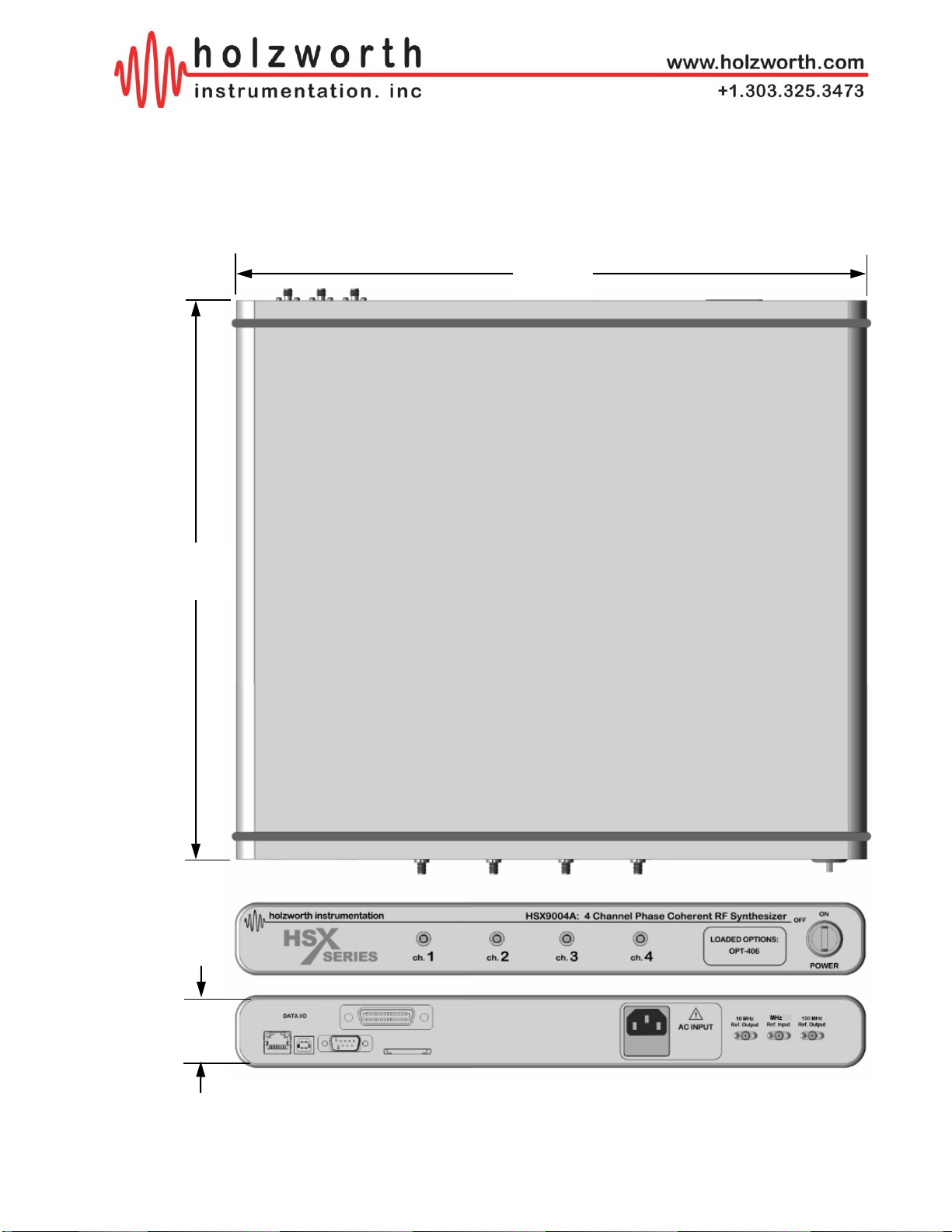
5.3 MECHANICAL CONFIGURATION.......................................................................7
5.4 ENVIRONMENTAL SPECIFICATIONS1...............................................................8
6.0 HARDWARE/SOFTWARE INSTALLATION ........................................................... 8
6.1 APPLICATION GUI OPERATION.........................................................................9
6.1.2 KEYBOARD AND MOUSE FUNCTIONS.......................................................9
6.2 USB, RS-232, AND GPIB COMMUNICATION....................................................10
6.2.1 IDENTIFY INSTRUMENT COM PORT & USB TROUBLESHOOTING ........11
6.2.2 GPIB COMMUNICATION..............................................................................12
6.3 ETHERNET COMMUNICATION .........................................................................13
6.3.1 LAN CONNECTION......................................................................................13
6.3.2 DIRECT PC CONNECTION (DHCP MODE).................................................14
6.3.3 ASSIGNING A STATIC IP ADDRESS ..........................................................14
6.4 TROUBLESHOOTING ETHERNET CONNECTIONS.........................................15
6.4.1 ETHERNET CONFIGURATION VIA USB & APPLICATION GUI .................15
6.4.2 MISCELLANEOUS ETHERNET TROUBLESHOOTING ..............................16
7.0 HARDWARE.......................................................................................................... 18
7.1 RF OUTPUT.......................................................................................................18
7.2 REFERENCE INPUT / OUTPUTS......................................................................18
7.2.1 10/100 MHz EXTERNAL REFERENCE........................................................18
7.2.3 REFERENCE OUTPUT ...............................................................................19
7.2.4 ATTENUATOR MODE.................................................................................19
7.3 HARDWARE INPUT/OUTPUT CONFIGURATION ............................................20
7.3.1 AC POWER SUPPLY ..................................................................................21
8.0 CONTACT INFORMATION.................................................................................... 21
APPENDIX A: ASCII Control of HSX Synthesizer.................................................... 22

HSX Series User Manual 1.14 www.holzworth.com Page 4 of 32
1.0 INTRODUCTION
Thank you for purchasing a Holzworth Instrumentation HSX Series Multi-Channel RF
Synthesizer module. The combination of Holzworth’s proprietary multi-loop synthesizer
architecture and the multi-channel integration provides the user with unique product
performance advantages which are currently only available from Holzworth Instrumentation Inc.
This User’s Manual is a quick reference guide for use with the Holzworth HSX Series Multi-
Channel RF Synthesizer products. Refer to section 5 for specific configuration details with
regards to the HSX Series hardware.
2.0 CERTIFICATIONS and EXEMPTIONS
2.1 CE CERTIFICATION
Holzworth multi-channel synthesizer products comply by test and design, with
the essential requirements and other relevant provisions of the EMC Directive:
2004/108/EC, and the Electrical equipment for measurement, control and
laboratory use EMC requirements (test standard): EN 61326-1: 2006;as set forth
by the Council of the European Union.
2.2 RoHS COMPLIANCE
Holzworth multi-channel synthesizer products are in compliance with Directive 2002/95/EC of
the European Parliament and of the Council of 27 January 2003 on the Restriction and use of
Certain Hazardous Substances in Electrical and Electronic Equipment (RoHS Directive).
3.0 PRODUCT WARRANTY
Holzworth HSX Series synthesizers come with a 3 year 100% product warranty covering
manufacturing defects. All product repairs and maintenance must be performed by Holzworth
Instrumentation Inc. Holzworth reserves the right to invalidate the warranty for any products
that have been tampered with or subjected to improper use. If the unit becomes damaged,
please contact Holzworth Instruments or your local representative for an RMA Number &
instructions prior to returning the unit for repair.
4.0 CALIBRATION NOTICE
Holzworth calibrates each channel for output frequency accuracy and output amplitude
accuracy. The factory calibration is valid for 2 years from the original calibration date. Holzworth
with model number and serial number for a calibration service quotation. Holzworth also makes
the calibration routine and equipment list available to customers who have the capability to
perform on site calibration. Contact support@holzworth.com for more information.

HSX Series User Manual 1.14 www.holzworth.com Page 5 of 32
5.0 HSX SERIES CONFIGURATION GUIDE
5.1 CONFIGURATION SUMMARY
The Holzworth HSX Series multi-channel platform is designed to achieve optimal channel-to-
channel stability across all integrated channel synthiesizers via a conductively cooled, fan-less
enclosure. Specific attention is paid to phase coherency between the independely controllable
channels. Internal channels offer better than -110 dB of channel-channel isolation.
The HSX Series is a unique platform allowing the user to specify custom configurations for a
COTS product. Units are loaded with anywhere from 1 to 4 channels (up to 6GHz). The HSX
Series provides industry leading phase noise and spectral purity performance, as well as
exceptionally high output power dynamic range from +20 to -110 dBm.
Each RF output is driven by a separate, internally loaded synthesizer module. Up to 4
independently tunable synthesizers can be specified per 1U chassis allowing for the highest
integrated channel density available in its class.
Holzworth HSX Series offer the benefits of a proprietary multi-loop based synthesis architecture.
Coupling the multi-loop architecture with a centralized reference distribution subsystem enables
truly phase coherent independently settable channels.
Different from traditional PLL based synthesizers, Holzworth’s proprietary multi-loop architecture
creates precisely synthesized signals that exhibit both instantaneous and long term stability.
Temperature variations between the channels remain the only contribution to drift. The
thermally optimized, fan-less chassis was specifically developed for maintaining the lowest
possible channel-to-channel thermal gradients.
Holzworth multi-channel designs are integrated into precision applications that include ATE
systems integration, particle accelerator, timing clocks, satellite position tracking and more.

HSX Series User Manual 1.14 www.holzworth.com Page 6 of 32
5.2 HARDWARE CONFIGURATION
The HSX Series synthesizer platform is a user defined platform. The configuration is
setup at the Holzworth factory based on the configuration defined by the end user.
Three primary categories define the final configuration of a unit.
5.2.1 NUMBER OF CHANNELS
The HSX part number signifies the number of independent channels available in the
unit. The current revision of the design is revision A. A four channel unit is defined as
an HSX9004A.
No. Channels
1
2
3
4
Part Number
HSX9001A
HSX9002A
HSX9003A
HSX9004A
NOTE: Amplitude accuracy may vary when operated outside of channel operating
temperature specified in section 6.3. Internal channel temperature should be monitored
using the ":TEMP?" command (see Appendix A). External cooling is recommended to
regulate internal temperature depending on ambient operating conditions and number of
integrated channels.
5.2.2 LOADED CHANNEL FREQUENCIES
The channel frequencies are defined at the time of a product purchase order. To
identify what channel frequencies are loaded, refer to the “Loaded Options” designator
scribed into the front panel of the instrument (at the left side of the power switch).
Frequency Range
Number of Channels per Frequency Range
1x
2x
3x
4x
10MHz - 6GHz
OPT-106
OPT-206
OPT-306
OPT-406
10MHz - 12GHz
OPT-112
OPT-212
OPT-312
OPT-412
10MHz –24GHz
OPT-120
OPT-220
OPT-320
OPT-420
10MHz - 40GHz
OPT-140
OPT-240
n/a
n/a
5.2.3 LOADED OPTIONS & AVAILABLE ACCESSORIES
Additional factory loaded options are also defined in the “Loaded Options” designator on
the front panel. These options further customize the HSX Series to an application and
are loaded at the factory when the unit is initially built. Accessories are external to the
HSX platform and can be ordered separately.
TYPE
Part Number
Description
ACCESSORY
RACK-1U
19" Rack Mount Bracket Kit, 90° Rear Brackets
ACCESSORY
RACK2-1U
19" Rack Mount Bracket Kit, Straight Rear Brackets

HSX Series User Manual 1.14 www.holzworth.com Page 7 of 32
5.3 MECHANICAL CONFIGURATION
The HSX Series comes in a 1U high, rack mountable chassis. The example shown is of
a 4 channel unit (front panel configuration may vary). A universal rack mount bracket kit
is an available accessory (Part No.: RACK-1U or RACK2-1U). Mechanical dimensions
are listed in inches (and millimeters).
TOP
1.75
(45)
REAR
FRONT
17.00
(432)
15.00
(381)

HSX Series User Manual 1.14 www.holzworth.com Page 8 of 32
5.4 ENVIRONMENTAL SPECIFICATIONS1
Environmental specifications are based on component margins, thermal verification testing and
current draw tests. Production unit performance is not verified over temperature.
PARAMETER
MIN
TYPICAL
MAX
COMMENTS
Operating Temperature
0 C
+55 C
Temperature Monitor Range
-40 C
+85 C
Channel Operating Temperature*
+35 C
+40 C
+45 C
Amplitude accuracy valid range
AC Power Supply
100 VAC
240 VAC
50 –60Hz
Power Consumption
Chassis
Channel (per)
5 W
17 W
Warm-Up Time
10 min
20 min
20 C (ambient temp. dependent)
1Specifications are subject to change per the discretion of Holzworth Instrumentation, Inc
*NOTE: Amplitude accuracy may vary when operated outside of channel operating
temperature specified in section 6.3. Internal channel temperature should be monitored
using the ":TEMP?" command (see Appendix A). External cooling is recommended to
regulate internal temperature depending on ambient operating conditions and number of
integrated channels.
DESCRIPTION
SPECIFICATION (by design)
Operating Environment
Humidity
Altitude
Vibration
RH 20% to 80% at wet bulb temp. <29C (non-condensing)
0 to 2,000m (0 to 6,561 feet)
0.21 G-rms maximum, 5Hz to 500Hz
Storage (Non-Operating)
Temperature
Humidity
Altitude Altitude
Vibration
-10C to + 60C
RH 20% to 80% at wet bulb temp. <40C (non-condensing)
0 to 4,572m (0 to 15,000 feet)
0.5 G-rms maximum, 5Hz to 500Hz
6.0 HARDWARE/SOFTWARE INSTALLATION
This section outlines the basic installation requirements and procedures for the HSX
Series Multi-Channel Synthesizer application GUI and the hardware either via USB or
Ethernet.
First, the application GUI software must be installed. The GUI software is contained on
the thumb drive that was included with the synthesizer module. If the thumb drive was
lost another can be emailed or the software can be downloaded after contacting
+1.303.325.3473 (option 2).

HSX Series User Manual 1.14 www.holzworth.com Page 9 of 32
6.1 APPLICATION GUI OPERATION
The Holzworth HSX Series GUI can be run on any Windows PC. There is no installation
required. Simply double click the executable file to launch the GUI. The latest version
can be downloaded by navigating to the URL below:
http://www.holzworth.com/software/Synthesizers/HSX/HSX9000.zip
NOTE: The Holzworth GUI can only be used to communicate with the instrument via
USB or Ethernet.
The Holzworth HSX Series Software can be used to change frequency, power, and
phase settings for individual channels as well as toggle each channel output on or off.
The RF output of each channel can be toggled using the circular buttons to the right of
each channel indicator. By default, the output power of all channels is set to "Off."
Click the REFERENCE button at the right of the GUI window set the instrument to utilize
an external 10MHz or 100MHz reference. By default it will use the on-board 100MHz
OCXO.
6.1.2 KEYBOARD AND MOUSE FUNCTIONS
As a virtual instrument, the PC keyboard and mouse functions are intuitively integrated
for ease of operation.
KEY
FUNCTION
Tab
used to move the Highlighted Field indicator from left to right
Left/Right Arrows
used to move the Highlighted Field both left and right
Up/Down Arrows
used to increase/decrease the value of the Highlighted Field
Number Keys
used to directly enter value into active field

HSX Series User Manual 1.14 www.holzworth.com Page 10 of 32
6.2 USB, RS-232, AND GPIB COMMUNICATION
With the HSX9000 USB and RS-232 communication are handled similarly in Windows.
USB communication requires FTDI drivers. Windows should install these drivers
automatically when the instrument is connected to the computer via USB. If the
instrument is not recognized, Windows may need to install updated USB drivers. These
are also included on the thumb drive that ships with the instrument.
Click the Devices button on the right side of the GUI, followed by the Locate Devices
button in the menu:
The software will then scan for instruments connected via USB. It will display USB
devices as shown below:
Identify the instrument by either serial # or COM port and select it. If the connection is
successful the window above 'Devices' will turn blue to indicate a USB connection,
and it will display the instrument serial number:
In order to create a custom USB software interface or application to control Holzworth
Synthesizers, the user must determine the COM port the instrument is using. The COM
port associated with the USB connection to the HSX9000 can be identified by using the
application GUI as shown above or via the Windows Device Manager.

HSX Series User Manual 1.14 www.holzworth.com Page 11 of 32
6.2.1 IDENTIFY INSTRUMENT COM PORT & USB TROUBLESHOOTING
To identify the instrument COM port using Windows Device Manager follow the steps
below:
1. Open the Windows Device Manager and check for the synthesizer in the 'Ports (COM
& LPT)' category.
STEP THREE
Under Ports (COM & LPT)
locate COM port associated
with the HA7062C (identified as
"USB Serial Port")
STEP ONE
Open the Windows Control
panel from the start menu.
Click on "Hardware and
Sound"
STEP TWO
Under "Devices and Printers,"
select Device Manager

HSX Series User Manual 1.14 www.holzworth.com Page 12 of 32
2. If the instrument is not present in Device Manager or in the Holzworth application GUI
please unplug the USB cable and power cycle the synthesizer. Wait 5-10 seconds for
the synthesizer to initialize an re-insert the USB cable. Click Locate Devices.
3. If the synthesizer is still not detected download the device drivers may need to be
manually installed. Download and extract the executable using the link below. Run the
executable to ensure the proper device drivers are installed.
Device drivers:
http://www.holzworth.com/software/Synthesizers/HSX/Installation/CDM21228_Setup.zip
After the executable has finished installing the drivers repeat troubleshooting Step 1.
4. Attempt to make a connection through a 'USB hub' if available. Upon connecting
through a hub it may be necessary to repeat troubleshooting Step 1.
5. Contact Holzworth Support for further assistance.
RS-232 HARDWARE SPECIFICATIONS
1. Connector: DB9 Male Shrouded.
2. Logic Level: ±5V
3. Baud Rate: 115200 FIXED.
4. Bit Structure: 8 Data Bits, 1 Stop Bit,
No Parity, No Flow Control
5. Carriage Return: Carriage return (ASCII Code 13)
6. Pinout:
6.2.2 GPIB COMMUNICATION
The Holzworth HSX9000 is GPIB capable. GPIB configuration commands are listed in
Appendix A.
PIN
Label
PIN
Label
PIN
Label
1
N/C
4
N/C
7
N/C
2
TX (Response Output)
5
GND
8
N/C
3
RX (Instruction Input)
6
N/C
9
N/C

HSX Series User Manual 1.14 www.holzworth.com Page 13 of 32
6.3 ETHERNET COMMUNICATION
Ethernet communication can be established with the HSX9000 by connecting the
instrument to a local area network or directly to a PC. Locating the instrument is
handled differently depending on the method of connection and DHCP settings that
have been assigned. By default, the HSX9000 is set to utilize DHCP when connected
over a network.
6.3.1 LAN CONNECTION
Communication with the HSX9000 over a LAN connection defaults to the use of DHCP.
The instrument can be addressed by using either the network assigned IP address or by
using the instrument serial (ex. "HSX9000-123") and the TCP port (9760). Use the
Holzworth Ethernet Finder software to locate and modify IP address settings on the
instrument.
To search for devices, click the Devices button and then click Locate Devices in the
sub menu.
The software will then scan for instruments connected via Ethernet and via serial port. It
will display Ethernet devices as shown below:
Identify the instrument by serial # or IP address and click to connect. If the connection is
successful the window above 'Devices' will turn green (Ethernet) and display the
instrument serial number:
Users can also enter the instruments IP address manually to connect. Enter the IP
address into the 'Device IP Address' field and then press the Connect button.
If the connection is successful the window above 'Devices' will turn green and display
the IP address.

HSX Series User Manual 1.14 www.holzworth.com Page 14 of 32
6.3.2 DIRECT PC CONNECTION (DHCP MODE)
When the HSX9000 is connected directly to a PC and it is set to DHCP, the instrument's
default IP address is: 169.254.117.11
This IP address can be used to establish communication with the HSX9000 when
connected directly.
6.3.3 ASSIGNING A STATIC IP ADDRESS
The most efficient way to assign the instrument a static IP address is to use the Console
in the Holzworth GUI. The Console can be used to send the commands from Appendix
B which are used to change the instrument from DHCP to Static, set the static IP, etc.
Users must first establish a USB connection or a direct Ethernet connection as
referenced in section 8.2 and 8.3.2, respectively.
Once a connection has been established, the Console can be launched by clicking the
Console button which is shown in the GUI Overview section, section 8.1. Now users can
begin sending the ASCII commands from Appendix B. The commands should be sent in
the order shown in the list and the Console screenshot below.
1. Send the command to change the static IP address.
•:IP:ADDR:<value>
2. Send the command to change the subnet address.
•:IP:SUBNET:<value>
3. Send the command to change the gateway if necessary.
•:IP:GATEWAY:<value>
4. Send the command to change from DHCP to Static.
•:IP:STATUS:STATIC
5. Power cycle the instrument when prompted.
When the instrument fully powers back on (5-10 second power up) it will come up with
the static IP settings and can be connected to the LAN.

HSX Series User Manual 1.14 www.holzworth.com Page 15 of 32
6.4 TROUBLESHOOTING ETHERNET CONNECTIONS
Prior to proceeding below press CTRL+ALT+DEL to open Windows Task Manager.
Click the Processes tab. Ensure that there is only one instance of the application GUI
open. If there are more than one, end each Holzworth process, re-launch the GUI, and
attempt to establish a connection.
6.4.1 ETHERNET CONFIGURATION VIA USB & APPLICATION GUI
1. If the synthesizer is not discovered by the application GUI there may be static
Ethernet settings that conflict with the current network configuration. USB
communication may be used to reset the synthesizer to DHCP or re-configure the static
network settings.
2. Establish a USB connection with the synthesizer as shown in section 8.1.
3. Launch the Console window using the button at the bottom right of the GUI. The
Console can be used to send ASCII commands to change static network settings or
change from static mode to DHCP and vice versa.
4. Refer to Appendix B for Ethernet configuration commands. Type commands into the
text field and then press Enter or click Send to send a command.
5. Begin by querying with the :IP:STATUS? command. Change status and/or re-
configure the static network settings as necessary.
6. Power cycle the HSX9000 if prompted. Any status change from DHCP to Static or
vice versa will require a power cycle.

HSX Series User Manual 1.14 www.holzworth.com Page 16 of 32
6.4.2 MISCELLANEOUS ETHERNET TROUBLESHOOTING
1. Ensure that the Holzworth software application is allowed through the firewall.
Additionally, ensure that anti-virus software is not blocking communication.
2. Using Windows Control Panel, disable Wi-Fi and any other hard-wired network
connections. Launch the Control Panel and proceed to Network and Internet, the
Network and Sharing Center. Click Change Adapter Settings.
3. In the Change Adapter Settings window right click on any network connections that
are not required for communication with the HA7062 and select Disable.
4. Close and re-launch the application GUI. Attempt to establish a connection with the
HSX9000.
5. If connection remains unsuccessful, reset the PC network adapter in use to DHCP
('Obtain IP address automatically') and reset the synthesizer to DHCP using either
method in the previous two sections.
6. Make a direct Ethernet connection from the PC to the synthesizer bypassing any
routers or network switches.

HSX Series User Manual 1.14 www.holzworth.com Page 17 of 32
7. Right click the network adapter the synthesizer is connected to and click Properties.
6. In Properties, left-click "Internet Protocol Version 4 (TCP/IPv4)", the Properties button
highlighted below will become available. Click the button and the window on the right
will open. Set to 'Obtain an IP address automatically'.
With a direct Ethernet connection between the PC and synthesizer both will default to
network settings that will allow communication.
The synthesizer IP address will default to 169.254.117.11 and the subnet address will
default to 255.255.0.0.
The PC IP address will default to 169.254.xxx.xxx and the subnet address will default to
255.255.0.0.
7. Close and re-launch the application GUI. Attempt to establish a connection to the
HSX9000.
8. For further assistance please contact Holzworth Support.

HSX Series User Manual 1.14 www.holzworth.com Page 18 of 32
7.0 HARDWARE
The HSX Series Multi-Channel RF Synthesizers are CW work horses. They are
designed to do a very good job of providing highly stable, phase coherent signals with
pure spectrums and highly accurate output power amplitude control.
7.1 RF OUTPUT
The RF Output ports are labeled and positioned sequentially from left to right on the
front panel of the instrument. The RF Output ports are protected against reflected
power with a maximum damage threshold of 25VDC (+10dBm or 10mW).
7.2 REFERENCE INPUT / OUTPUTS
The reference input and output ports are
located on the right side of the rear panel.
NOTE that the internal reference distribution
subsystem must be manually set for the type
of reference being used. The factory default
setting is for the internal reference (free
running). Users can change the reference
setting using the Application GUI or by
sending ASCII commands.
7.2.1 10/100 MHz EXTERNAL REFERENCE
When a 10MHz or 100MHz External Reference signal is applied and External 10MHz or
External 100MHz is selected in software, the system enables a 20Hz digital PLL which
phase locks the internal OCXO to the external reference signal. The internal OCXO
remains operating in both scenarios to maintain optimal phase noise levels at >20Hz
offset. The performance of the synthesized channel output signals as well as the fixed
10MHz and 100MHz Reference Output signals are based on the 10 or 100MHz external
reference for offsets of <20Hz; performance is based on the integrity of the 100MHz
internal OCXO at offsets of >20Hz.
This architecture is often used in laboratories and systems as a cleanup loop for 10MHz
Rubidium, Cesium, GPS disciplined, etc. references; as it provides an optimal reference
signal for the internal channels as well as both the 10MHz and 100MHz reference
outputs.

HSX Series User Manual 1.14 www.holzworth.com Page 19 of 32
7.2.3 REFERENCE OUTPUT
Holzworth multi-channel synthesizer modules supply very clean 10MHz and 100MHz
Reference Outputs under all operating conditions.
An outline of the reference input vs. output configuration is captured as follows:
Reference Input
Internal
100MHz
OCXO
100MHz Reference Out
10MHz Reference Out
None (free running)
ACTIVE
Matches Internal 100MHz OCXO
Divided from internal 100MHz OCXO.
10MHz Signal applied
ACTIVE
Based on:
Internal 100MHz OCXO (>20Hz OS)
External 10MHz (<20Hz OS)
Divided from:
Internal 100MHz OCXO (>20Hz OS)
External 10MHz (<20Hz OS)
100MHz Signal applied
ACTIVE
Based on:
Internal 100MHz OCXO (>20Hz OS)
External 100MHz (<20Hz OS)
Divided from:
Internal 100MHz OCXO (>20Hz OS)
External 100MHz (<20Hz OS)
7.2.4 ATTENUATOR MODE
NOTE: The following information applies to OPT-n03 (3GHz) and OPT-n06 (6GHz)
channels only.
Holzworth HSX synthesizer channels are equipped with an attenuator module to allow
for very high dynamic range. There are four different modes the attenuator can be
operated in depending on the requirements of the application. Table 1 below describes
each attenuator mode and Table 2 indicates which power levels are available in each
attenuator state. The attenuator mode can be configured by sending the commands
from the power settings section of Appendix A.
Attenuator Mode
Description
AUTO
Synthesizer adjusts attenuator
automatically
HIGH
Attenuator set to 0dB state. Valid for
power levels +5dBm to +20dBm
NORMAL
Attenuator sets from 10dB to 120dB.
Valid for all power levels +5dBm and
below. 0dB (high power) state disabled
FIX
Attenuator state fixed to whichever
state it is currently in (e.g. if the
synthesizer is in the 10dB attenuator
state and the FIX command is sent, it
will remain in the 10dB state and not
allow power levels outside of this state)
Attenuator State
Power Level
120dB
110dB
100dB
90dB
80dB
70dB
60dB
50dB
40dB
30dB
20dB
10dB
0dB
≤ -105.00dBm
≤ -95.00dBm
≤ -85.00dBm
≤ -75.00dBm
≤ -65.00dBm
≤ -55.00dBm
≤ -45.00dBm
≤ -35.00dBm
≤ -25.00dBm
≤ -15.00dBm
≤ -5.00dBm
≤ +5.00dBm
>+5.00dBm
Table 1: Atten. Mode Descriptions
Table 2: Atten. States

HSX Series User Manual 1.14 www.holzworth.com Page 20 of 32
7.3 HARDWARE INPUT/OUTPUT CONFIGURATION
The HSX Series ships standard with region-specific AC power cord as well as the
cables necessary for USB and Ethernet communication with the instrument.
REAR PANEL
DESCRIPTION
SPECIFICATION
Reference Output Port
Connector Type
Output Frequency
Output Level
Output Waveform
SMA, 50ohm
10/100MHz ±10Hz
+5dBm ±2dBm
Sinusoid
Reference Input Port
Connector Type
Input Frequency
Input Level
SMA, 50ohm
10MHz ±10Hz
0dBm to +15dBm (Sinusoid or Square)
AC Power Input
Connector Type
AC Input Rating
IEC 320-C13
100-240VAC, 47-63Hz. Specify country at time of order.
Data I/O Interface
Connectivity
Storage
USB B-Type (virtual comm. port), Ethernet, RS-232, GPIB
SD Card Reader (currently inactive)
HSX Series Communication Ports
This manual suits for next models
4
Table of contents
Other Holzworth Instrumentation Synthesizer manuals