manuals.online logo
Brands
  1. Home
  2. •
  3. Brands
  4. •
  5. Home
  6. •
  7. Indoor Furnishing
  8. •
  9. Home Scandinavia - Chest of drawers User manual

Home Scandinavia - Chest of drawers User manual

Scandinavia - Chest of drawers
Dimensions
Width - 78cm
Depth - 40cm
Height - 71cm
Issue 3 - 23/11/2016
Important – Please read these instructions fully before starting assembly
If you need help or have damaged or missing parts, call the Customer Helpline: 03456 400800
Assembly Instructions
476/8654
487/7174
Retain these instructions for future reference
Sainsbury’s Argos
489-499 Avebury Boulevard
Saxon Gate West
Central Milton Keynes
MK9 2NW
1
Safety and Care Advice
Important – Please read these instructions fully before starting assembly
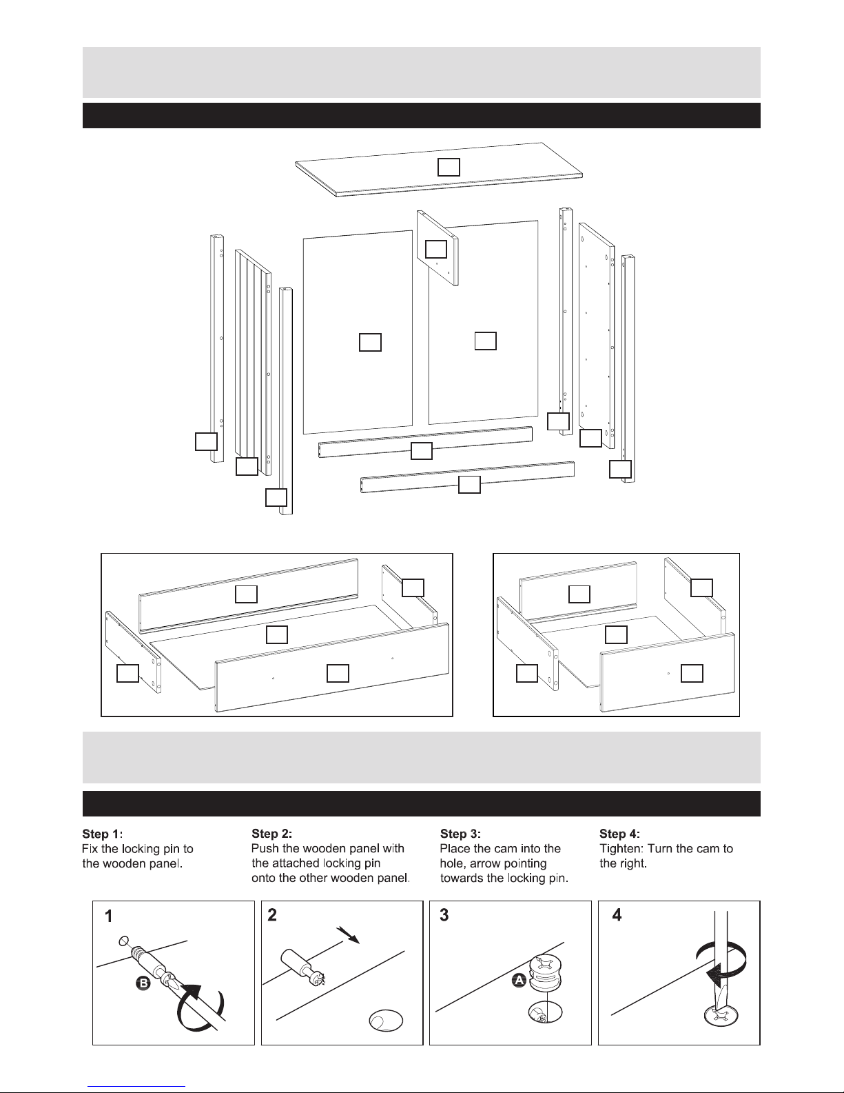
Note: if required the next
page can be cut out and used
as reference throughout the
assembly. Keep this page with
these instructions for future
reference.
• Only clean using a damp cloth
and mild detergent, do no use
bleach or abrasive cleaners.
• From time to time check that
there are no loose screws on
this unit.
• This product should not be
discarded with household
waste. Take to your local
authority waste disposal centre.
Care and maintenance
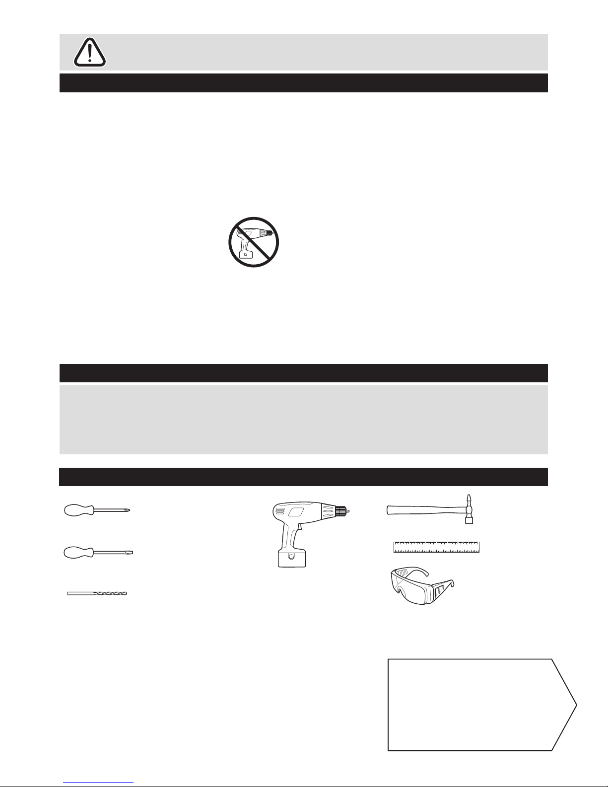
Tools required
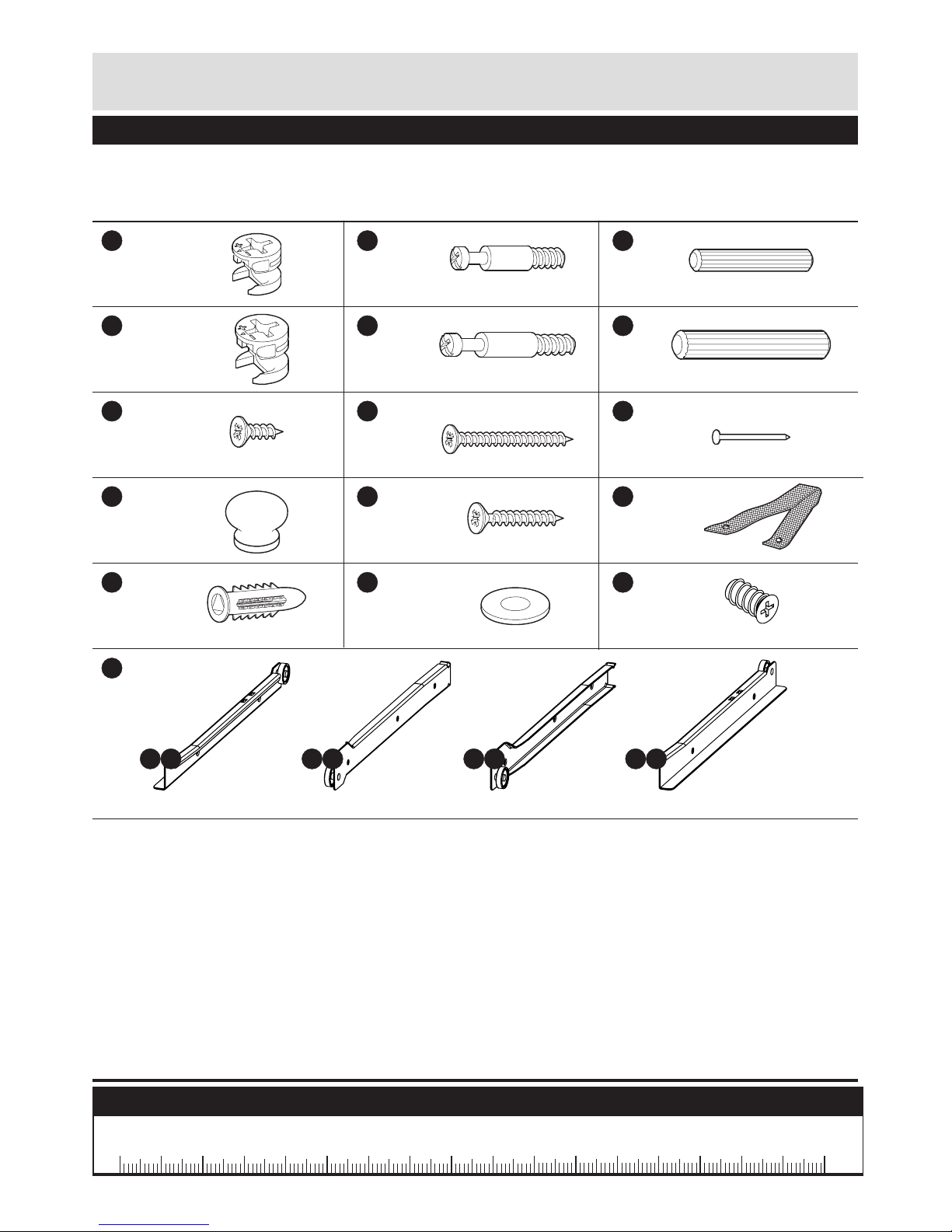
0 10 20 30 40 50 60 70 80 90 100 110 120 130 140 150
0 1 2 3 4 5 6
Phillips screwdriver
(medium & large)
Flatblade screwdriver
(medium)
Small
hammer
Ruler/tape
measure
Drill
Eye protection
(when using a
hammer or glue)
7mm Suitable drill bit
(for use with wall plug)
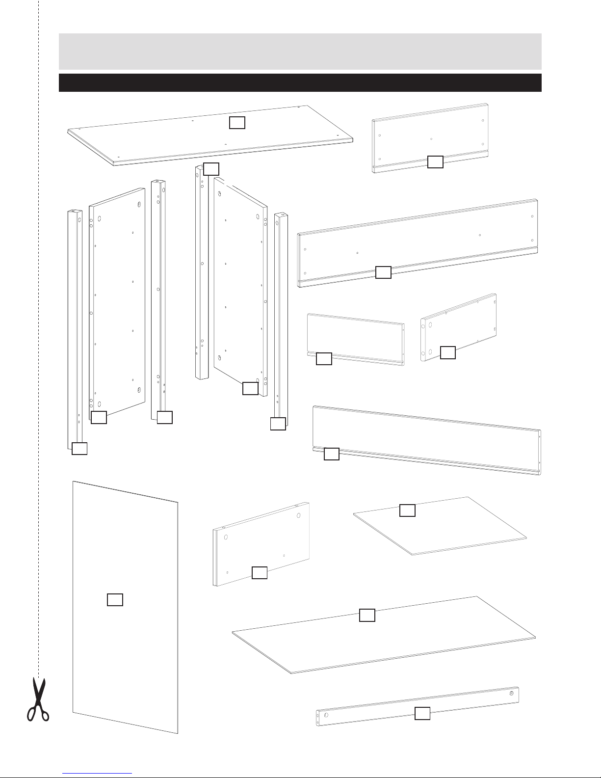
• Check you have all the
components and tools listed on
pages 2 and 3.
• Do not use this item if any
components are missing or
damaged.
• Remove all ttings from the
plastic bags and separate them
into their groups.
• Keep children and animals
away from the work area, small
parts could choke if swallowed.
• Make sure you have enough
space to layout the parts before
starting.
• Do not stand or put weight on
the product, this could cause
damage.
• Assemble the item as close
to its nal position (in the same
room) as possible.
• Assemble on a soft level
surface to avoid damaging the
unit or your oor.
• Parts of the assembly will be
easier with 2 people.
• We do not
recommend the
use of power
drill/drivers for
inserting screws,
as this could damage the unit.
Only use hand screwdrivers.
• Dispose of all packaging
carefully and responsibly.
• Assembly to be carried out by
a competent adult only
• During assembly children
should be kept away from the
product due to possible risk of
injury.
• Folding and unfolding this
product should only be carried
out under adult supervision.
• Ensure that ngers and legs
are clear of all adjustments
when adjusting this product.
• Regularly check all fastenings
to ensure that they properly
tightened.
2
Components - Panels
Please check you have all the panels listed below
Front left leg
67x 3.2cm)
2
Front right leg
(67 x 3.2cm)
5
Left side panel
(62.6 x 30cm)
1
Back x 2
(60x34.4 cm)
10
Small drawer back x 2
(28 x 11cm)
13
Large drawer back x 3
(62 x 11cm)
16
Large drawer front x 3
(66.6 x 14cm)
15
Small drawer front x 2
(32.4 x 14cm)
11
Large drawer bottom x 3
(64 x 33cm)
17
Small drawer bottom x 2
(30 x 33cm)
14
Plinth x 2 (67 x 4.4cm)
9
Divider (36.6 x 14.5cm)
8
Top (78 x 40cm)
7
Right side panel
(62.6 x 30cm)
4
Drawer side x 10
(34 x 10cm)
12
Back left leg
(67 x 3.2cm)
3
Back right leg
(67 x 3.2cm)
6
If you have damaged or missing components,
call the Customer Helpline:
03456 400 800
3
Please check you have all the ttings listed below
Cam 12 mm x 30
Cam 15 mm x 8
Screw 14 mm x 1
Knob x 8
Wall plug x 1
Screw 35 mm x 28
Screw 20 mm x 1
Washer x 2
Nail x 30
Wall strap x 1
Screw x 40
Drawer runners x 5
Locking pin 34 mm x 8 Dowel 40 mm x 12
Locking pin 24 mm x 30 Dowel 30 mm x 4
Ruler - Use this ruler to help correctly identify the screws
A
D
G
J
M
P
H
K
N
I
L
O
P 1 P 2 P 3 P 4
E F
B C
Note: The quantities below are the correct amount to complete the assembly. In some cases more ttings
may be supplied than are required.
100 20 30 40 50 60 70 80 90 100
0510 15 20 25 30 35 40 45 50 55 60 65 70 75 80 85 90 95 100 110 115 120 125 130 135 140 145 150 155 160 165 170
105
Components - Fittings
4
Components - Key Diagram
Function of Cam and Locking Pin
9
10
17
16
x3 x2
15 1112
12
12
12
13
14
8
7
10
9
2
5
1
4
3
6
Left side Right side
5
Assembly Instructions
Step 1
Step 2
Inserting the dowels
and mounting the
locking pins to the
legs.
Insert the dowels F
into the holes indicated
on the legs 2and 3.
Screw the locking pins
Einto the holes
indicated on the legs
2and 3.
Note: Insert locking pins
E as far as shown. Do
not over tighten.
Mounting legs to the side
panels.
Fit the legs 2and 3.
onto the side panel 1.
Note: See page 5
“Function of cam and
locking pin“.
Place the cams Dinto the
holes indicated on the side
panel 1.
To tighten cams: Turn to
the right using a
screwdriver.
2
2
2
3
1
1
3
D
D
D
D
D
F
F
F
F
F
F
F
E
E
E
E
E
Rebate=Back
6
Step 3
Inserting the dowels
and mounting the
locking pins to the
assembled side.
Insert the dowels Cinto
the holes indicated
Screw the locking pins
Binto the holes
indicated on the legs
2and 3.
Note: Insert locking pins
Bas far as shown. Do
not over tighten.
2
2
3
3
1
1
2
O
O
O
O
O
O
O
O
C
CB
B
B
C
Step 4
Attaching the drawer
runners to the
assembled side.
Fix the drawer runners
P 3 to the left side 1,
P 2 to the right side 4
using screws Othrough
the holes indicated
To tighten screws:
Turn to the right using a
screwdriver.
Repeate these steps
with right side.
Assembly Instructions
Left side
Left side
P 3
P 3
P 3
P 3
7
Step 6
Step 7
Adding the plinths to
the left side.
Fit the left side 1onto
the plinths 9.
Note: See page 5
“Function of cam and
locking pin“.
Place the cams Ainto
the holes indicated on the
plinths 9
To tighten cams: Turn to
the right using a
screwdriver.
Adding the plinths to
the right side.
Fit the right side 4onto
the plinths 9.
Note: See page 5
“Function of cam and
locking pin“.
Place the cams Ainto
the holes indicated on the
plinths 9.
To tighten cams: Turn to
the right using a
screwdriver.
Assembly Instructions
9
9
1
1
4
9
9
9
9
Left side
Right side
Left side
A
A
A
A
A
A
Rebate=Back
Rebate=Back
8
Step 8
Step 9
Step 10
Attaching drawer
runners to the divider.
Fix the drawer runner P 2
to the divider left side and
the drawer runner P 3 to
the divider right side with
screws O into the holes
indicated on the divider
8.
Mounting the locking
pins to the top.
Screw the locking pins B
into the holes indicated
on the top 7.
Note: Insert locking pins
Bas far as shown. Do
not over tighten.
Assembling the divider
to the top.
Fit the divider 8onto
the top 7.
Note: See page 5
“Function of cam and
locking pin“.
Place the cams Ainto
the holes indicated on
the divider 8.
To tighten cams: Turn to
the right using a
screwdriver.
Assembly Instructions
8
8
7
7
O
O
O
B
B
B
A
A
A
B
B
B
B
O
Front edge
P 2
P 3
Rebate=Back
9
Assembly Instructions
Step 11
Assembling the top to
the sides.
Attach the top 7onto
the sides 1and 4.
Note: See page 5
“Function of cam and
locking pin“.
Place the cams Ainto
the holes indicated on the
sides 1and 4.
To tighten cams: Turn to
the right using a
screwdriver.
7
7
A
A
AA
A
Rebate=Back
Right side Left side
14
Rebate=Back
Right side
10
Assembly Instructions
Step 12
Adding the back to the
carcass.
Carefully turn the
assembled piece of
furniture, with the back to
the top.
Place the back 10 into the
rebate of the top 7and
the side 4.
Ensure thet there is no gap
between the side back, not
between the top and the
back.
Fasten the back with
nails Ialong the top.
The angle between the
top and the side must be
90 degrees.
To accomplish this,
ensure that there is no
gap between the right side
4and the
back 10 .
Fasten the back with
nails Ialong the side.
Place the back 10 into the
rebate of the top 7and
the side 1.
Ensure thet there is no gap
between the side back, not
between the top and the
back.
Fasten the back with
nails Ialong the side and
the plinth.
10
4
7
4
1
10
10
9
I
IIII
I
IIIII
Right side
Left side
90O
11
Assembly Instructions
Step 13
Large drawer assembly.
a: Fix the drawer sides
12 to the drawer back 16
using screws H.
b: Slide the drawer bottom
17 into the grooves of the
drawer back 16 .
c: Screw the locking pins
Binto the holes indicated
on the drawer front 15 .
Note: Insert locking pins
Bas far as shown. Do
not over tighten.
d: Press the drawer front
15 onto the drawer sides
12 .
Note: See page 5
“Function of cam and
locking pin“.
Place the cams Ainto
the holes indicated on
the drawer side 12 .
To tighten cams: Turn to
the right using a
screwdriver.
16
16
17
15
16 12
12
12
15
12
12
12
12
H
H
H
B
B
A
A
A
A
B
B
H
12
Assembly Instructions
e: Fix the knobs Jto the
drawer front 15 using
screws H.
f: Fix the drawer runners
P 1 and P 4 to the
drawer sides 12 using
screws Othrough the
holes indicated.
Repeate with remaining
drawer.
15
12
J
H
O
O
O
OO
O
H
J
1P
1P
4P
13
Assembly Instructions
Step 14
Small drawer assembly.
a: Fix the drawer sides
12 to the drawer back 13
using screws H.
b: Slide the drawer bottom
14 into the grooves of the
drawer back 13 .
c: Screw the locking pins
Binto the holes indicated
on the drawer front 11 .
Note: Insert locking pins
Bas far as shown. Do
not over tighten.
d: Press the drawer front
11 onto the drawer sides
12 .
Note: See page 5
“Function of cam and
locking pin“.
Place the cams Ainto
the holes indicated on
the drawer side 12 .
To tighten cams: Turn to
the right using a
screwdriver.
B
B
BB
A
A
A
A
A
12
12
12
13
13
14
11
11
11
13
12
12
12
H
H
H
H
14
e: Fix the knob Jto the
drawer front using screw
H.
f: Fix the drawer runners
P 1 and P 4 to the
drawer sides 12 using
screws Othrough the
holes indicated.
Assembly Instructions
J
H
11
O
O
4P
O
O
1P
12
ф
Adding the drawers to
the carcass.
Slide the drawers onto
the drawer runners.
Step 14
Repeate with remaining
drawer.
15
Assembly Instructions
ф
Fixing to wall
It is recommended that
the drawer chest is xed
to a wall.
Fix wall strap Lto top
of drawer chest using
screw G.
With help, move drawer
chest into position.
Warning:
The drawer
chest is heavy.
Lift with care.
Mark xing hole on wall
and remove storage.
Drill 7mm hole and insert
wall plug M.
Warning: Before
drilling, check
wall for hidden
pipes and
cables.
Reposition drawer chest
and x wall strap using
screw K.
Assembly is complete.
Step 14
If you need help or have damaged or missing parts, call the Customer Helpline: 03456 400 800
Domestic address or Home Retail Group Plc address.
K
L
N
M
NG
16
A Guide to - Wall Mounting & Fixings
Important note:
If plastic wall plugs
are supplied with
your product:
- these are only suitable for
use in masonry walls.
If you are in any doubt about
the correct wall plugs for
your wall, seek professional
advice.
Failure of the product due to
using incorrect fixings is the
responsibility of the installer.
Types of walls
Important:When drilling into walls always
check that there are no hidden wires or pipes etc.
Make sure that the screws and wall plugs being used are
suitable for supporting your unit. Consult a qualified
tradesperson if you are unsure.
Hints:
1: General rule: Always use a larger screw and wall plug
if you are not sure.
2: Ensure you use the recommended drill bit to match the wall
plug and hole size.
3: Ensure you drill the hole horizontally, do not force the drill or
enlarge the hole.
4: Take extra care when drilling high walls, ceilings and ceramic
tiles. Ensure wall plugs are inserted beyond the thickness of
the ceramic tiles to avoid the tiles splitting or cracking.
5: Ensure wall plugs are well fitted and are a tight fit in the
drilled hole.
You can use one of the following types of wall plug if your walls are
made of brick, breeze block, concrete, stone or wood.
No.1 “General Purpose” wall plug
Generally aerated blocks should not
be used to support heavy loads, use
a specialist fitting in this case. For light
loads, general purpose wal plugs can
be used.
No.2 “Plasterboard” wall plug
For use when attaching light loads on
to plasterboard partitions.
Care &
Maintenance
No.3“Cavity Fixing” wall plug
For use with plasterboard partitions or
hollow wooden doors.
No.4 “Cavity Fixing-Heavy Duty”
wall plug
For use when fitting or supporting
heavy loads such as shelving, wall
cabinets and coat racks.
Safety: Always check the fitting
and location to ensure your safety
in and around the home.
No.5 “Hammer Fixing” wall plug
For use with walls stuck with
plasterboard. The hammer fixing allows
it to be fixed to the wall rather than the
plasterboard. Always check the fixing
is secure to the retaining wall.
No.6 “Shield Anchor” wall plug
Heavy loads
For use with heavier loads such as TV
& HiFi speakers and satelite dishes etc.
Fitting: From time to time check
the fitting to ensure the wall plugs
or screws do not become loose.
17
Dear Customer
Please note that the product you have purchased is a
natural living timber.
Just like nature itself, wood varies in shape and colour.
Knots, vein patterns, resin pockets and colour differences
contribute to giving the piece of furniture its beauty and
form - a natural part of solid wood.
Although the tree has been cut down and dried, it is still
alive and therefore will react to high and low
temperatures, light, humidity, drought and time.
In cold and dry periods, the wood contracts which may
lead to small cracks in the piece of furniture. The reverse
happens in warm and humid periods where the wood
expands and this may result in slight unevenness.
The colour of the wood also changes with time,
particularly if the furniture is placed in a light place. This
is a natural process and part of owning a piece of
furniture made of solid wood.
Any flexing that has occurred during transport will
re-correct itself once this product is correctly assembled.
Tighten all joints of the furniture after six months.
Please keep these instructions in a safe place for future
use.

This manual suits for next models

2

Other Home Indoor Furnishing manuals

Home Argyll User manual

Home

Home Argyll User manual

Home Gloss Single Wall Cabinet White 525/8974 User manual

Home

Home Gloss Single Wall Cabinet White 525/8974 User manual

Home Nordic Overbed Fitment User manual

Home

Home Nordic Overbed Fitment User manual

Home SIENA 51M User manual

Home

Home SIENA 51M User manual

Home 8507086 User manual

Home

Home 8507086 User manual

Popular Indoor Furnishing manuals by other brands

URBAN OUTFITTERS Juliette Queen Bed Assembly instructions

URBAN OUTFITTERS

URBAN OUTFITTERS Juliette Queen Bed Assembly instructions

PLACES OF STYLE Luna525 Assembly instructions

PLACES OF STYLE

PLACES OF STYLE Luna525 Assembly instructions

Allen + Roth L-DN1779SAL-A-RC Assembly instructions

Allen + Roth

Allen + Roth L-DN1779SAL-A-RC Assembly instructions

Nienkamper GATEWAY installation guide

Nienkamper

Nienkamper GATEWAY installation guide

Vinsetto 920-071V70 Assembly & instruction manual

Vinsetto

Vinsetto 920-071V70 Assembly & instruction manual

Emmezeta ALA Assembling instructions

Emmezeta

Emmezeta ALA Assembling instructions

Allen + Roth RENZO 18W installation manual

Allen + Roth

Allen + Roth RENZO 18W installation manual

SAFAVIEH COUTURE Doyle SFV8700A Assembly

SAFAVIEH COUTURE

SAFAVIEH COUTURE Doyle SFV8700A Assembly

Mainstays Entertainment Center instruction manual

Mainstays

Mainstays Entertainment Center instruction manual

Dunelm Toulouse Gents 30168623 Assembly instructions

Dunelm

Dunelm Toulouse Gents 30168623 Assembly instructions

KI Engage Task Chair Disassembly instructions

KI

KI Engage Task Chair Disassembly instructions

Argos Puerto Rico 332/6901 Assembly instructions

Argos

Argos Puerto Rico 332/6901 Assembly instructions

LIVARNO 90024 Assembly and Safety Advice

LIVARNO

LIVARNO 90024 Assembly and Safety Advice

Granberg Baselift Corner 6301H installation instructions

Granberg

Granberg Baselift Corner 6301H installation instructions

RH Baby&child French Library Shelving quick start guide

RH Baby&child

RH Baby&child French Library Shelving quick start guide

Yosemite Home Decor YFUR-SBA1324200 manual

Yosemite Home Decor

Yosemite Home Decor YFUR-SBA1324200 manual

BLACK RED WHITE PORTO S322-SZF3D2S Assembly manual

BLACK RED WHITE

BLACK RED WHITE PORTO S322-SZF3D2S Assembly manual

Bestar 60W 107420-230035 Assembly instructions

Bestar

Bestar 60W 107420-230035 Assembly instructions

manuals.online logo
manuals.online logoBrands
  • About & Mission
  • Contact us
  • Privacy Policy
  • Terms and Conditions

Copyright 2025 Manuals.Online. All Rights Reserved.