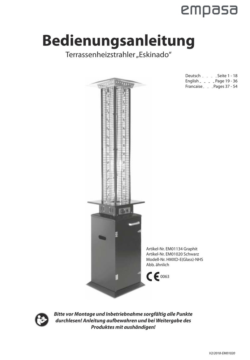
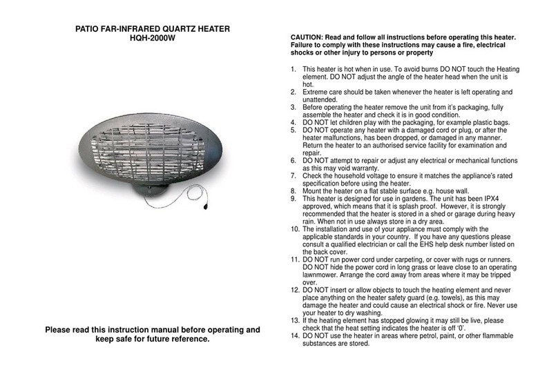
Homebase PTG018S User manual

1 x Heater 1 x Top Wire Frame
1 x Top Plate
1 x Base
PTG018S
1 x Middle Wire Frame
1 x Quick Connector
A4 x Screw B3 x Nut C3 x Spacer Screw
Homebase Ltd.
Avebury, Milton Keynes, MK 9 2NW. For further information contact
Customer Service: 0845 0778888
www.homebase.co.uk.
Simple Assembly Instructions - Please keep for future reference
IMPORTANT
1. Read these instructions carefully and
familiarise yourself with the procedure
before assembling the unit.
2. Check that you have all the component
parts following the list on the back
cover and familiarise yourself with
each part before proceeding.
3. Take all the fittings out of the plastic bag
and separate them into their groups.
4. Ensure you have enough space to lay out
all the parts before assembly.
Table Top Patio Heater
Components
5. To avoid scratching it is recommended
that you assemble the unit on a soft
level surface.
10-05
Fittings
A B
C
D
E
F

IMPORTANT SAFETY INSTRUCTIONS
NOTE
• This appliance must be installed and the gas cylinder stored in accordance
with the regulations in your area.
• The tubing or flexible hose must be changed within the prescribed intervals.
Check with your gas supplier.
• Use only the type of gas and cylinder specified by the manufacturer.
• In case of wind particular attention must be taken against tilting or falling over
of the appliance.
• Only for use outdoors and in well ventilated areas.
• A well ventilated area must have minimum of 25% of the surface area open.
• The surface area is the sum of the walls surface.
WARNING
• KEEP CHILDREN AND PETS AWAY.
• Do not obstruct the ventilation holes of the cylinder housing.
• Do not move the appliance when in operation.
• Shut off the valve at the gas cylinder or the regulator before moving the
appliance.
• Care should always be taken in handling this Heater to avoid accidental injury.
• Do not use the Heater indoors.
• This Heater is for outside use only and should be placed on a flat non-combustible
surface and be located in an open area with good ventilation.
• Do not move the Heater whilst it is hot or alight.
• Do not use flammable liquids such as petrol or kerosene for lighting or relighting
as this may be hazardous.
• The appliance must not be used in basements or below ground level.
CARE OF THE HEATER
• Store the Heater inside or protect with a suitable cover.
• To avoid any risk of suffocation to animals or children dispose of the plastic
bags immediately.
• As with all surfaces clean with a damp cloth and mild detergent, do not use
bleach or abrasive products.
• From time to time please ensure there are no loose screws on the product.
• You must check the tubing or the flexible hose at least once per month and
each time the cylinder is changed
"Read all instruction before use" and keep for future reference.
Please follow carefully all assembly instructions in this manual. Failure
to do so could result in serious harm.

NOTE: It would be useful to ask
someone to help you at this
stage.
1. Carefully locate the Heater A on
top of the Base D.
See fig. 1.
2. Use Screws Ato fix the Heater
Aonto the Base D.
See fig. 2.
3. Use Nuts Bto fix the Top Wire
Frame B on the unit. Ensure they
are well fitted.
See fig. 4.
2. Use Spacer Screws Cto fix the
Top Plate C on the unit.
See fig. 3.
NOTE: Carefully fit the hose and
ensure that it is well fitted &
not trapped by any parts.
1. Carefully fit the Middle Wire Frame
Eusing the hooks to locate into
the Heater Frame.
See fig. 3.
NOTE: Ensure the frames are
properly fitted before fitting the
Top Plate.
IMPORTANT:
Please read the important safety
instructions before use.
AA
A
B
C
fig. 3
C
E
fig. 3
Hook
Assembly Instructions Assembly Instructions
Stage 2 – Fitting the Top PlateStage 1 – Fitting the Base
fig. 1
A
D
fig. 2 A
D
B
fig. 4

CAUTION:
NOTE: Make sure the Quick
Connector F is securely
connected before proceeding.
1.5m
Assembly Instructions Assembly Instructions
Stage 4 – PreparationStage 3 – Operating the Quick Connector
You will need to purchase a Butane
gas bottle size 7kg or 15kg to
operate this Heater which can be
obtained from your nearest gas
retailer. (Ensure the gas bottle type
is suitable for the regulator supplied)
NOTE: The gas hose connecting
the appliance to the gas bottle
should not exceed the
recommended length of 1.5m.
See fig. 8.
Please read the important safety
instructions before use.
Regulator
fig. 8
Connect the Quick Connector F
1. Slide the collar of Quick Connector
Fback and insert the other end of
Quick Connector F.
See fig. 5.
2. Gently tug on the gas hose to test
for proper connection. If the
connection moves it is not secure.
Repeat steps. Do not proceed
until you have a proper
connection.
See fig. 6.
Disconnect the Quick Connector
1. Slide the collar of Quick Connector
Fback and gently pull the
connector apart.
See fig. 7.
fig. 5
fig. 6
F
F
fig. 7
F

NOTE: Always test the gas hose
for leaks at connectors with
soapy water after finishing.
Apply caution when changing
the gas bottle and keep away
from naked flames.
NOTE: Be careful not to kink
flexible portion of gas hose. General Information
WARNING: The Minimum Safe
Distance between the Gas
Cylinder and any other
combustable materials should
be a Minimum of 1.0m. Do not
place flamable material close to
the burner as this is a Hazard.
Place the Unit on a Level
Surface where it will not be
easily knocked over and away
from Children and Pets.
• Only change the gas cylinder in
well ventilated areas away from
any inflammation source (candle,
cigarettes other flame producing
appliances...).
• Ensure that the regulator seal is
fitted and in good condition.
• Turn off the gas at the regulator
or gas cylinder after use.
How to disconnect the gas bottle:
1. Check that the control knob and
regulator are in the OFF position.
2. Disconnect the regulator from the
gas bottle valve.
3. Position gas bottle below or near
heater.
4. Attach gas hose to gas bottle -
make sure the lever is in the down
position and push in with your
thumb while pushing regulator
down firmly until a "click" is heard.
Release thumb from lever.
See fig. 9.
Assembly Instructions Assembly Instructions
Stage 4 – Preparation
Type of Regulator to be used:
• Low pressure L.P. Gas Regulator.
• Nom. Outlet Press. 37 mbar
• Max. Inlet Press. 20 bar
• Propane LR2527A
• British Standard : BS3016
• Safety ø27 Interlock
See fig. 10. Regulator
fig. 10 Gas
Bottle
Stage 4 – Preparation
How to connect the gas bottle:
1. Check that the control knob and
regulator are in the OFF position.
2. Slide hose clamp over each end
of hose. Slide hose over nozzle of
regulator. Route hose through
table before connecting to nozzle.
Tighten clamps.
Gas bottle connection
Regulator
fig. 9 Gas
Bottle

Technical Information
Homebase MK9 2NW
Model no. PTG018S
Total Heat Output: 4.5 kW Gas Consumption: 327 g/h
Gas Category: I3+(28-30/37)
Type of Gas: Propane
Gas Pressure: 37 mbar
Injector Size: 1.05 mm
Pin Number: 359/BQ/568
Serial Number
Data Code
Countries For Use GB and IE
The specifications and external appearance of this unit are subjected to change
without notice.
NOT FOR DOMESTIC USE
Warning: Accessable parts may be very hot. Keep young children away.
Read the instruction literature before using this appliance. The appliance must
installed in accordance with the instructions and local regulations.
Close the valve of the gas cylinder or the regulator after use.
For use outdoors and in well ventilated areas.
The use of the appliance in enclosed areas can be dangerous and is prohibited.
This appliance requires installation by a competent person
The appliance shall not be used in basement or below ground level
Only for use in well ventilated areas, with a minimum of 25% of the surface area
open.
The surface area is the sum of the walls surface.
fig. 11
HIGH
LOW
OFF
ON
Control Knob
Assembly Instructions Assembly Instructions
Specifications
Stage 5 – Operation
Igniting the Heater automatically:
1. Turn the Control Knob clockwise to "OFF" position.
See fig. 11.
2. Turn the gas supply "ON" at the cylinder regulator.
3. Push in the Control Knob on the Heater whist turning anti-clockwise to the "Ignition"
position (a clicking sound is heard), this will light the burner. If the burner does not
light, repeat this process.
See fig. 11.
4. When the burner is lit, keep the Control Knob pressed in for 15 seconds and then
release it.
5. If the burner does not stay alight, repeat steps 3 and 4. Adjust the heat by turning
the Knob anti-clockwise to the High/Low position.
6. To turn the heater 'OFF' turn the appliance clockwise to the 'OFF' position. Then
turn the cylinder valve or regulator switch to the 'OFF' position.
CAUTION:
- If burner fails to ignite, turn the control knob and the gas bottle valve to the
off position. Wait five minutes before attempting to re-light the unit.
NOTE:
- The other burners will automatically cross light from the left to the right side
once the initial burner is ignited.
Table of contents