MaxxGarden Terrasverwarmer User manual

1
Terrasverwarmer
GEBRUIKERSHANDLEIDING
MODE D’EMPLOI
BEDIENUNGSANLEITUNG
USER’S MANUAL
MANUAL DE USUARIO
MANUALE D’USO
INSTRUKCJA OBSŁUGI
ANVÄNDARMANUAL
NL: Terrasverwarmer
FR: Chauffe-terrasse
DE: Terrassenheizer
EN: Patio heater
ES: Calentador de patio
IT: Riscaldatore per patio
PL: Grzejnik tarasowy
SE. Uteplats värmare
Model: 21012

2
INHOUD
Waarschuwing............................................................................................................................................ 3
Stand en locatie terrasverwarmer ........................................................................................................... 5
Gasvereisten............................................................................................................................................... 5
Lekkagetest ................................................................................................................................................ 5
Werking en opslag..................................................................................................................................... 5
Reiniging en onderhoud ........................................................................................................................... 6
Onderdelen en specicaties .................................................................................................................... 6
Montageonderdelen en procedures...................................................................................................... 7
Checklist voor problemen....................................................................................................................... 11

3
[NL] GEBRUIKERSHANDLEIDING
Bewaar de instructies voor toekomstig gebruik
WAARSCHUWING VEILIGHEIDSVOORSCHRIFTEN
LEES DEZE INSTRUCTIES ZORGVULDIG DOOR VOORDAT U UW NIEUWE TERRASVERWARMER GEBRUIKT.
VOOR JOUW VEILIGHEID
Als u gas ruikt:
1. Sluit het gas naar het toestel af.
2. Doof open vuur.
3. Als de geur aanhoudt, bel dan onmiddellijk uw gasleverancier of uw brandweer.
VOOR JOUW VEILIGHEID
1. Bewaar of gebruik geen benzine of andere brandbare dampen en vloeistoffen in de buurt
van dit of enig ander apparaat.
2. Een gases die niet is aangesloten voor gebruik, mag niet in de buurt van dit of enig ander
apparaat worden opgeslagen.
WAARSCHUWING
1. Gebruik het toestel buiten of in goed geventileerde ruimtes.
2. Een goed geventileerde ruimte moet minimaal 25% van de oppervlakte open hebben.
3. De oppervlakte is de som van de oppervlakte van de muren.
WAARSCHUWING
Onjuiste installatie, afstelling, wijziging, service of onderhoud kan letsels of materiële schade
veroorzaken. Lees de installatie-, bedienings- en onderhoudsinstructies grondig voordat u deze
apparatuur installeert of onderhoudt.
WAARSCHUWING
Lees de instructies voor installatie en gebruik.
- Dit apparaat moet worden geïnstalleerd en de gases moet worden opgeslagen in
overeenstemming met de geldende voorschriften.
- Blokkeer de ventilatieopeningen van de cilinderbehuizing niet.
- Verplaats het apparaat niet als het in werking is.
- Sluit de klep bij de gases of de regelaar voordat u het toestel verplaatst.
- De slang of de exibele slang moet binnen de voorgeschreven intervallen worden vervangen.
- Gebruik alleen het type gas en het type cilinder dat door de fabrikant is gespeciceerd.
- Bij harde wind moet bijzondere aandacht worden besteed zodat het apparaat niet kan
kantelen.
WAARSCHUWING
- Laat een verwarmingstoestel niet onbewaakt achter, zeker niet als er ook kinderen of
huisdieren aanwezig zijn.
- Verwarmingstoestellen op gas of petroleum hebben voldoende verluchting nodig. Stop dus
niet alle kieren dicht. Anders bestaat er gevaar voor CO-vergiftiging.
- Wees voorzichtig met verwarmingstoestellen, leg er niets op en plaats ze op voldoende
afstand van brandbare voorwerpen.
- Gebruik enkel elektrische toestellen met een veilig snoer.
- Schakel toestellen die je niet gebruikt volledig uit, zeker als je slaapt of niet thuis bent.
- Controleer je verwarmingstoestel regelmatig. Een slecht werkende installatie kan leiden
tot brand.

4
WAARSCHUWING
LEES DE VOLGENDE VEILIGHEIDSRICHTLIJNEN ZORGVULDIG DOOR VOORDAT U HET TOESTEL
GEBRUIKT
• Gebruik de terrasverwarmer niet binnenshuis, dit kan persoonlijke letsels of materiële schade
veroorzaken.
• Deze terrasverwarmer is niet bedoeld voor installatie op recreatievoertuigen en / of boten.
• Installatie en reparatie moeten worden uitgevoerd door een gekwaliceerde servicemonteur.
• Onjuiste installatie, afstelling, wijziging kan persoonlijke letsels of materiële schade veroorzaken.
• Probeer het apparaat op geen enkele manier te veranderen.
• Vervang de regelaar nooit door een andere regelaar dan de door de fabriek voorgestelde
vervanging.
• Bewaar of gebruik geen benzine of andere brandbare dampen of vloeistoffen in de
verwarmingseenheid.
• Het hele gassysteem, de slang, de regelaar, de waakvlam of de brander moet voor gebruik
worden geïnspecteerd op lekkage of beschadiging, en minimaal jaarlijks door een
gekwaliceerd servicemonteur.
• Alle lektesten moeten worden uitgevoerd met een zeepoplossing. Gebruik nooit een open vlam
om op lekken te controleren.
• Gebruik de terrasverwarmer niet voordat alle aansluitingen op lekkage zijn getest.
• Draai de gasklep onmiddellijk dicht als u een gaslucht ruikt. Draai de cilinderklep UIT. Als er een
lek is bij de slang- / regelaaraansluiting: draai de aansluiting vast en voer nogmaals een lektest
uit. Als er bellen blijven verschijnen, moet u deze terugbrengen naar de plaats van aankoop
van de slang. Als er een lek is bij de aansluiting van de regelaar / cilinderklep: ontkoppel, sluit
opnieuw aan en voer nogmaals een lekcontrole uit. Als u na verschillende pogingen nog steeds
bellen ziet, is de cilinderklep defect en moet deze worden teruggestuurd naar de plaats van
aankoop van de cilinder.
• Vervoer de terrasverwarmer niet terwijl deze in werking is.
• Verplaats de terrasverwarmer niet nadat deze is uitgeschakeld en het toestel is afgekoeld.
• Houd de ventilatieopening van de cilinderbehuizing vrij en vrij van vuil.
• Verf het stralingsscherm, het bedieningspaneel of de reector van de bovenkap niet.
• Regelcompartiment, brander en circulatieluchtkanalen van de terrasverwarmer moeten
zuiver worden gehouden.
Regelmatig reinigen kan nodig zijn.
• De LPG-tank moet worden uitgeschakeld wanneer de verwarming niet in gebruik is.
• Controleer de verwarming onmiddellijk als één van de volgende situaties zich voordoet:
- De kachel komt niet op temperatuur.
- De brander maakt een knallend geluid tijdens het gebruik (een klein geluid is normaal
als de brander uit is).
- Geur van gas in combinatie met extreem kantelen van de brandervlammen.
• De LP-drukregelaar / slangconstructie moet buiten paden worden geplaatst waar mensen
erover kunnen struikelen of in een gebied waar de slang niet per ongeluk beschadigd kan
raken.
• Elke beschermkap of andere beschermingsinrichting die is verwijderd voor onderhoud aan
de kachel, moet worden vervangen voordat de kachel wordt gebruikt. Volwassenen en
kinderen moeten uit de buurt blijven van de oppervlakken met hoge temperaturen om
brandwonden of ontbranding van kleding te voorkomen.
• Kinderen moeten zorgvuldig worden begeleid wanneer ze zich in de buurt van de kachel
bevinden.
• Kleding of andere brandbare materialen mogen niet aan de kachel worden opgehangen
of op of naast de kachel worden geplaatst.
• De gases moet worden vervangen in een goed geventileerde ruimte, uit de buurt van
ontstekingsbronnen (kaars, sigaretten, andere apparaten die vlammen produceren, ...).
• Controleren of de afdichting van de regelaar correct is aangebracht en zijn functie kan
vervullen.
• De ventilatieopeningen van de cilinderbehuizing mag niet worden geblokkeerd.
• Bij gaslekkage mag het toestel niet worden gebruikt of bij brand moet de gastoevoer
worden afgesloten en moet het toestel worden onderzocht en gerepareerd worden voordat
het opnieuw wordt gebruikt.
• De aanbevolen frequentie voor het controleren van de slang of de exibele slang (minstens
één keer per maand en elke keer dat de cilinder wordt vervangen). Als het tekenen van
barsten, splijten of andere slijtage vertoont, moet het worden vervangen door een nieuwe
slang van dezelfde lengte en van gelijkwaardige kwaliteit.

5
STAND EN LOCATIE VAN DE TERRASVERWARMER
• De terrasverwarmer is uitsluitend bedoeld voor gebruik buitenshuis.
Zorg er altijd voor dat er voldoende ventilatie met verse lucht is.
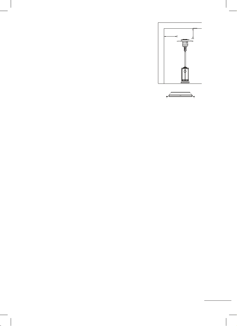
• Houd altijd voldoende afstand tot brandbare materialen,
d.w.z. bovenkant 100 cm en zijkanten minimaal 100 cm.
• De terrasverwarmer moet op een vlakke, stevige ondergrond
worden geplaatst.
• Gebruik de terrasverwarmer nooit in een explosieve atmosfeer,
zoals in gebieden waar benzine of andere brandbare vloeistoffen
of dampen worden opgeslagen.
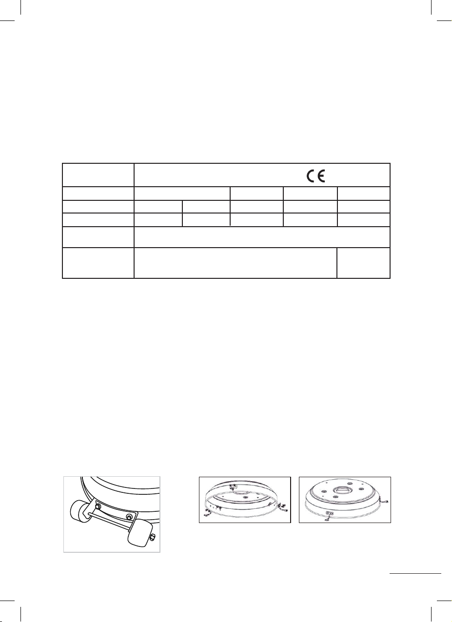
• Om de terrasverwarmer tegen sterke wind te beschermen,
verankert u de basis stevig aan de grond met schroeven.
GASVEREISTEN
• Gebruik alleen propaan- of butaangas.
• De te gebruiken drukregelaar en slang moeten voldoen aan de lokale standaardcodes.
• De installatie moet voldoen aan lokale codes, of bij afwezigheid van lokale codes, aan de norm
voor de opslag en behandeling van vloeibare petroleumgassen.
• Een gedeukte, verroeste of beschadigde propaantank kan gevaarlijk zijn en moet worden
gecontroleerd door uw tankleverancier. Gebruik nooit een propaantank met een beschadigde
klepaansluiting.
• De propaantank moet zo zijn ingericht dat de damp uit de werkende cilinder kan worden
afgevoerd.
• Sluit nooit een ongeregelde propaantank aan op de kachel.
LEKKAGE TEST
De gasaansluitingen op de terrasverwarmer worden voorafgaand aan verzending in de fabriek
op lekkage getest. Op de plaats van installatie moet een volledige gasdichtheidscontrole worden
uitgevoerd vanwege mogelijke verkeerde behandeling tijdens het transport of vanwege
overmatige druk die op de verwarmer wordt uitgeoefend.
• Maak een zeepoplossing van een deel vloeibaar wasmiddel en een deel water. De zeep-
oplossing kan worden aangebracht met een spuites, borstel of doek. Bij een lek ontstaan er
zeepbellen.
• De kachel moet worden gecontroleerd met een volle cilinder.
• Zorg ervoor dat de veiligheidsklep in de UIT-stand staat.
• Zet de gastoevoer AAN.
• In geval van een lek, de gastoevoer afsluiten. Draai eventuele lekkende ttingen vast, draai de
gastoevoer weer aan en controleer opnieuw.
• Test nooit op lekkage tijdens het roken.
WERKING EN OPSLAG
DE KACHEL INSCHAKELEN
1. Draai de klep op de gastoevoeres volledig open.
2. Druk en draai de variabele bedieningsknop naar de PILOT-stand (90º linksom).
3. Druk de variabele bedieningsknop in en houd deze 30 seconden ingedrukt. Terwijl u de
variabele bedieningsknop ingedrukt houdt, drukt u meerdere keren op de ontstekingsknop
totdat de waakvlam gaat branden. Laat de variabele bedieningsknop los nadat de waakvlam
is ontstoken.
Nota:
• Als er zojuist een nieuwe tank is aangesloten, geef dan minimaal een minuut de tijd om de
lucht in de gasleiding door het geleidegat te laten ontsnappen.
• Zorg er bij het aansteken van de waakvlam voor dat de variabele bedieningsknop continu
wordt ingedrukt terwijl de ontstekingsknop wordt ingedrukt. Variabele bedieningsknop kan
worden losgelaten nadat de waakvlam is ontstoken.
• De waakvlam kan worden bekeken en gecontroleerd vanuit het kleine ronde raampje met
schuifdeksel aan de onderkant van het vlamscherm (links of rechts van de controller).
• Indien de waakvlam niet aangaat of dooft, herhaal stap 3.
4. Nadat de waakvlam is ontstoken, draait u de variabele bedieningsknop naar de maximale
stand en laat u deze daar 5 minuten of langer op staan voordat u de knop naar de gewenste
temperatuurstand draait.
- 2 -
HEATER STAND AND LOCATION
The heater is primarily for outdoor use only. Always ensure that
adequate fresh air ventilation is provided.
Always maintain proper clearance to combustible materials, i.e. top 100 cm
and sides 100 cm minimum.
Heater must be placed on level firm ground.
Never operate heater in an explosive atmosphere like in areaswhere
gasoline or other flammable liquids or vapors are stored.
To protect heater from strong wind, anchor the base securely to the
ground with screws.
GAS REQUIREMENTS
Use propaneor butane gas only.
The pressure regulator and hose assembly to be used must conform to local standard codes.
The installation must conformto local codes, or in the absence of local codes, with the standard for the
storage and handling of liquid petroleum gases.
A dented, rusted or damaged propane tank may be hazardous and should be checked by your tank
supplier. Never use a propane tank with a damaged valve connection.
The propane tank must be arranged to provide for vapor withdrawal from the operating cylinder.
Never connect an unregulated propane tank to the heater.
LEAKAGE TEST
Gas connections on the heater are leaktested at the factory prior to shipment. A complete gas tightness
check must be performed at the installation site due to possible mishandling in shipment or excessive
pressure being applied to the heater.
Make a soap solution of one part liquid detergent and one part water. The soap solution can be applied
with a spray bottle, brush or rag. Soap bubbles will appear in case of a leak.
The heater must be checked with a full cylinder.
Make sure the safety control valve is in the OFF position.
Turn the gas supply ON.
In case of a leak, turn off the gas supply. Tighten any leaking fittings, then turn the gas supply on and re-
check.
Never leak test while smoking.
CEILING
WALL
100 cm
100 cm
Fortification of base to the ground
LO
HI
Off
Igniter
Pilot
PLAFOND
MUUR
Versterking van de basis naar de grond

6
DE KACHEL UITZETTEN
1. Draai de variabele bedieningsknop
naar de PILOT-stand.
2. Druk en draai de variabele bedieningsknop
naar de UIT-stand.
3. Draai de klep op de gastoevoeres volledig dicht.
Opslag
1. Sluit altijd de gaskraan van de gases na gebruik of bij een storing.
2. Verwijder de drukregelaar en de slang.
3. Controleer de dichtheid van de gasklep en controleer deze op beschadigingen.
Als u schade vermoedt, laat deze dan vervangen door uw gasdealer.
4. Bewaar essen met vloeibaar gas nooit op een ondergronds terrein of op plaatsen
zonder voldoende ventilatie.
REINIGING EN ONDERHOUD
• Veeg gepoedercoate oppervlakken af met een zachte, vochtige doek. Reinig de
terrasverwarmer niet met reinigingsmiddelen die brandbaar of bijtend zijn.
• Verwijder vuil van de brander om deze schoon en veilig voor gebruik te houden.
• Dek de branderunit af met de optionele beschermkap als de kachel niet in gebruik is.
ONDERDELEN EN SPECIFICATIES
Variable control knob
Igniter
TO TURN ON THE HEATER
1. Turn on the valve on the gas supply cylinder completely.
2. Press and turn the variable control knob to PILOT position (counter-clockwise 90º).
3. Press down the variable control knob and hold for 30 seconds. While holding down the variable control knob,
press the igniter button several times until the pilot flame lights. Release the variable control knob after the pilot
flame lights.
Note:
If a new tank has just been connected, please allow at least one minute for the air in the gas pipeline to purge out
through the pilot hole.
When lighting the pilot flame make sure that the variable control knob is continuously pressed down while pressing
the igniter button. Variable control knob can be released after the pilot flame lights.
Pilot flame can be watched and checked from the small round window with sliding lid located at the bottom of the
flame screen (to the left or right side of the controller).
If the pilot flame does not light or it goes out, repeat step 3.
4. After the pilot flame lights, turn the variable control knob to maximum position and leave it there for 5 minutes or
more before turning the knob to desired temperature position.
TO TURN OFF THE HEATER
1.Turn the variable control knob to PILOT position.
2.Press and turn the variable control knob to OFF position.
3.Turn off the valve on the gas supply cylinder completely.
Storage
1. Always close the gas valve of the gas cylinder after use or in case of a disturbance.
2. Remove the pressure controller and the hose.
3. Check the tighness of the gas valve and for damage. If you suspect damage, have it changed by your gas dealer.
4. Never store liquid gas cylinder in a sub-terrain, or at places without adequate air ventilation.
lgniter
Hi
Pilot
Off
CLEANING AND CARE
•Wipe off powder coated surfaces with soft, moist rag. Do not clean heater with cleaners that
are combustible or corrosive.
•Remove debris from the burner to keep it clean and safe for use.
•Cover the burner unit with the optional protective cover when the heater is not in use.
PARTS AND SPECIFICATIONS
- 4 -
2180 mm
780 mm
813 mm
445 mm
Reflector
Flame screen
Burner base
Air admittance fence
Gas valve controller
Base of control housing
Post
Tank housing
Post bracket
Stand
LO
HI
Off
Igniter
Pilot
Variabele bedieningsknop
Ontsteker
Reector
Paal
Tankbehuizing
Paal beugel
Voet
Vlamscherm
Brander basis
Luchtinlaatafrastering
Gasklep controller
Basis van besturingsbehuizing

7
A. Constructie en kenmerken
• Verplaatsbare terras- / tuinverwarmer met tankbehuizing
• Behuizing in staal met poedercoating of roestvrij staal
• Warmteafgifte van reector
B. Specicaties
• Gebruik alleen propaan- of butaangas
• Max. wattage: 13000 watt
• Min. wattage: 5000 watt
• Met CE-certicaten
C. Tabel injector
• De combinatie van slang en regelaar moet voldoen aan de lokale standaardcodes.
• De uitlaatdruk van de regelaar moet voldoen aan de overeenkomstige gascategorie in
de tabel van de injector.
• Het apparaat heeft een goedgekeurde slang met een lengte van 1,2 m nodig.
MONTAGE ONDERDELEN EN PROCEDURES
Benodigd gereedschap:
• Steeksleutel 10 & 13 mm
• Verstelbare openingssleutel (2) 20 cm lang
• Schuifverbindingstang 23 cm lang
• Kruiskopschroevendraaier met medium blad
• Spuites zeepoplossing voor lektest
Geleverde onderdelen:
• Statief met LPG-cilinderbehuizing en 3 paalbeugels.
• 9 potmoeren (M6 mm), 9 kleine schroeven (M6 x 8 mm) voor reectormontage.
• 6 grote bouten en ensmoeren (M6) voor steunpoten / hoofdmastmontage.
• 3 middelgrote bouten (M8 x 16 mm) voor steunpoten / standaardmontage.
• 3 reectorafstandhouders en vleugelmoeren, 6 grote platte ringen voor reector en brander.
• 2 medium bouten (M8x16 mm) voor wielen en voet.
• 6 kleine bouten (M6x12) en M6 moeren voor verankeringsarm en basis.
MONTAGEPROCEDURES
Bevestig het wielstel aan de basis
met 2 stuks medium bouten (M8x16mm)
- 6 -
ASSEMBLY PARTS AND PROCEDURES
Tools needed:
Open end wrench 10 & 13 mm
Adjustable opening wrench (2) 20 cm long
Slip joint pliers 23 cm long
Philips screwdriver w/ medium blade
Spray bottle of soap solution for leakage test
Parts supplied:
Stand with LPG cylinder housing and 3 post brackets.
9 Cup Nuts (M6 mm),9 Small Screws (M6 x 8 mm) for Reflector Assembly.
6 Large Bolts and Flange Nuts (M6) for Support Legs/Main Pole Assembly.
3 Medium Bolts (M8 x 16 mm) for Support Legs/Stand Assembly.
3 Reflector Spacers and Wing Nuts, 6 Large Flat Washers for Reflector and burner Assembly.
2 Medium Bolts (M8x16 mm) for wheels and base.
6 Small bolts (M6x12) and M6 nuts for anchoring arm and base.
ASSEMBLY PROCEDURES
Attach wheel assembly to base with 2pcs Medium bolts (M8x16mm)
Attach 1 anchoring arm to base with 2 small bolts M6x12mm and 2pcs M6 nuts as shown
(repeat with the other 2anchoring arms so all 3 are attached to base).
Bevestig 1 verankeringsarm aan de basis met 2 kleine
bouten M6x12mm en 2 stuks M6 moeren, zoals afgebeeld
(herhaal met de andere 2 verankeringsarmen zodat ze
alle 3 zijn bevestigd aan de basis).
GAS CATEGORIE:
SOORTEN GAS:
GAS DRUK:
TOTALE WARMTE
INGANG (Hs): (Qn)
INJECTOR GROOTTE
I
3+(28-30/37)
Butaan
28-30 mbar
1,90 voor hoofdbrander
0,18 mm voor waakvlambrander
1,68 voor hoofd-
brander
0,18 mm voor
waakvlambrander
13kW (870 g/h)
Propaan
37 mbar
LPG Gasmengsel
30 mbar
LPG Gasmengsel
37 mbar
LPG Gasmengsel
50mbar
I
3B/P(30)
I
3B/P(37)
I
3B/P(50)
2575-21
Pin: 2575DM30400
MODEL 21012 TERRASVERWARMER

8
STAP 1
1-1. Plaats de 3 stuks paalbeugels op elke positie op
de basis zoals weergegeven in de afbeelding.
1-2. Gebruik 3 medium bouten (M8x16) om de paalbeugels
en de standaard te verbinden.
STAP 2
2-1. Plaats de paal bovenop 3 stuks paalbeugels.
2-2. Gebruik 6 grote bouten en ensmoeren (M6) om
de paal aan de 3 stuks paalbeugels te bevestigen.
Draai de bouten en moeren vast.
STAP 3
Plaats de tankbehuizing op de standaard.
- 7 -
STEP 1
1-1. Put the 3 pcs post brackets on each position on the base as
shown in the picture.
1-2. Use 3 Medium Bolts(M8x16) to join the post brackets and stand.
STEP 2
2-1. Put the post on the top of 3 pcs post brackets.
2-2. Use 6 Large Bolts and Flange Nuts (M6) to connect the post tothe
3 pcs post brackets. Tighten the bolts and nuts.
STEP 3
Place the tank housing on the stand.
Bolt
Post
STEP 2
Nut
STEP 3
Bolt
Stand
Post bracket
STEP 1
Tank housing
Paalbeugel
Bout
Moer
Bout
tankbehuizing
Standaard
Paal
STAP 1
STAP 2
STAP 3

9
STAP 4
4-1. Verwijder de 4 bouten van de brander.
4-2. Steek de gasslang door de paal.
4-3. Bevestig de branderunit aan de paal met de 4 bouten.
STAP 5
5-1. Controleer of de verbinding van de verticale paal
en brander volgens de instructies is gemonteerd en
of alle bouten en moeren zijn aangedraaid.
5-2. Plaats 3 stuks grote platte ringen op 3 reectorafstandhouders.
STAP 6
Bevestig de reector met 3 stuks grote platte ringen
en 3 stuks vleugelmoeren.
- 8 -
STEP 4
4-1. Remove the 4 bolts from the burner.
4-2. Put the gas hose through into the post.
4-3. Fix the burner unit to the post by the 4 bolts.
STEP 5
5-1. Check whether the connection of vertical post and burner are
assembled according to instructions, and all bolts and nuts are
tightened.
5-2. Put 3 pcs Large Flat Washers on 3 Reflector Spacers.
STEP 6
Fasten the reflector with 3 pcs Large Flat Washers and 3 pcs Wing Nuts.
STEP 4
Bolt
STEP 5
STEP 6
Reflector
Wing nut
Reflector Spacer
Reector
afstandhouder
Vleugelmoer
Reector
Bout
STAP 4
STAP 5
STAP 6

10
STAP 7
7-1. Breng de tankbehuizing omhoog en laat deze op
de paalplaat rusten.
7-2. Sluit de regelaar aan op de gastank en draai
deze vast met een verstelbare sleutel.
7-3. Sluit de eindschroefdraad van de inlaatgasslang
aan op de regelaar.
7-4. Zet LPG-gastank op de standaard.
- 9 -
STEP 7
7-1. Bring up the tank housing and rest it on the post plate.
7-2. Connect the regulator to the gas tank and tighten it with adjustable
wrench.
7-3. Connect the end thread of inlet gas hose to the regulator.
7-4. Put LPG gas tank on the stand.
PROBLEMS CHECK LIST
PROBLEM PROBABLE CAUSE SOLUTION
Pilot will not light Gas valve may be OFF Turn the gas valve ON
Tank fuel empty Refill LPG tank
Opening blocked Clean or replace opening
Air in supply system Purge air from lines
Loose connections Check all fittings
Pilot will not stay on Debris around pilot Clean dirty area
Loose connections Tighten connections
Thermocouple bad Replace thermocouple
Gas leak in line Check connections
Lack of fuel pressure Tank near empty. Refill LPG tank.
Burner will not light Pressure is low Tank near empty. Refill LPG tank.
Opening blocked Remove and clean
Control not ON Turn valve to ON
Thermocouple bad Replace thermocouple
Pilot light assembly bent Place pilot properly
Not in correct location Position properly and retry
STEP 7
Regulator
Gas tank
Regelaar
Gas tank
STAP 7

11
NL. PROBLEEMCHECKLIST TERRASHEATERS
PROBLEEM TOESTAND MOGELIJKE OPLOSSING
Brander ontsteekt niet
OPMERKING
verwarming werkt met
een verminderde efciëntie
onder 5 °C
Brander blijft niet branden
Brander ontsteekt niet
Brandervlam is laag
OPMERKING
verwarming werkt met
een verminderde efciëntie
onder 5 °C
Koolstofophoping
Ongelijkmatige gloed
Flash back
(vlam in brander)
Dikke zwarte rook
Als u het probleem niet kunt oplossen met een van de genoemde oplossingen, neem dan contact op met uw dealer of de
verantwoordelijke distributeur.
Bedieningsknop staat niet in
maximale positie(grote vlam).
Vuil opgehoopt rond brander.
Lage vlammen of niet volledig
draaiende rond de brander.
Thermokoppel werkt niet correct.
Lage gasdruk.
Bedieningsknop niet op ‘Low’.
Brander niet goed op zijn plaats.
Buitentemperatuur is hoger dan
5 ˚C en LPG-cilinder is lager dan
25% vol.
Gasleiding is gebogen of geknikt.
Bedieningsknop staat niet in
maximale positie(grote vlam).
Vuil of lm op brander.
Gasdruk te laag.
Basis staat niet vlak, stevig en/of
waterpas.
Branderpoorten zijn geblokkeerd.
Verstopping in de brander.
LPG-cilinderklep is
gesloten / leeg.
Verstopping in de injector.
Lucht in het gascircuit.
Lage gasdruk.
Ontsteker mislukt.
Losse/lekkende aansluitingen.
Draai de regelknop naar maximum
positie (grote vlam).
Maak vuil rond de brander schoon.
Vlamverspreidergaten gedeeltelijk gesloten;
maak de brander schoon.
Vervang thermokoppel (FSD).
Vervang de LPG-cilinder door een nieuwe.
Draai bedieningsknop op ‘Low’.
Bevestig brander correct en probeer
opnieuw.
Vervang de LPG-cilinder door een nieuwe.
Leg de slang recht en voer een lektest uit op
de gasleiding.
Draai de bedieningsknop naar de “UIT”
-stand, laat afkoelen tot kamertemperatuur
en controleer de brander en de openingen
op verstopping.
Reinig de brander.
Reinig de brander.
Vervang de gases.
Plaats de voet op een vlakke, stevige en
horizontale ondergrond.
Schakel het apparaat UIT. Sluit de klep van
de LPG-cilinder. Wacht 2 minuten en volg de
ontstekingsprocedure. Ontsteek de brander.
Als het probleem aanhoudt, schakel dan uit.
Neem contact op met uw dealer.
Draai de bedieningsknop naar de stand
“OFF”, laat het apparaat afkoelen tot kamer-
temperatuur, verwijder de verstopping en
reinig de brander van binnen en van buiten.
Open de klep / vervang de LPG-
cilinder door een nieuwe.
Injector reinigen of vervangen.
Open de gasleiding en ontlucht deze (door
de regelknop in te drukken) gedurende niet
langer dan 1 minuut of totdat u gas ruikt.
Vervang de LPG-cilinder door een nieuwe.
Gebruik lucifer om brander aan te steken;
vervang de batterij of zorg voor een nieuwe
ontsteking en vervang deze.
Controleer de aansluitingen.

12
CONTENU
Avertissement ...........................................................................................................................................13
Position et emplacement des chauffages de terrasse .......................................................................15
Besoins en gaz ..........................................................................................................................................15
Essai d’étanchéité ...................................................................................................................................15
Fonctionnement et stockage .................................................................................................................15
Nettoyage et entretien ...........................................................................................................................16
Pièces et spécications ...........................................................................................................................16
Pièces et procédures de montage .......................................................................................................17
Liste de contrôle pour le dépannage ...................................................................................................21

13
[FR] MODE D’EMPLOI
Conservez les instructions pour référence future
AVERTISSEMENT DE SÉCURITÉ DE L’AVERTISSEMENT DE SÉCURITÉ DE L’AVERTISSEMENT
VEUILLEZ LIRE ATTENTIVEMENT CES INSTRUCTIONS AVANT D’UTILISER VOTRE NOUVEAU CHAUFFE-
TERRASSE.
POUR VOTRE SÉCURITÉ
Si vous sentez une odeur de gaz :
1. Fermez le gaz de l’appareil.
2. Éteindre les ammes ouvertes.
3. Si l’odeur persiste, appelez immédiatement votre fournisseur de gaz ou votre service d’incendie.
POUR VOTRE SÉCURITÉ
1. Ne stockez pas et n’utilisez pas d’essence ou d’autres vapeurs et liquides inammables à
proximité de cet appareil ou de tout autre équipement.
2. Ne stockez pas une bouteille de gaz qui n’est pas connectée pour être utilisée à proximité
de cet appareil ou de tout autre appareil.
ATTENTION
1. Utilisez l’appareil à l’extérieur ou dans des zones bien ventilées.
2. Une zone bien ventilée doit avoir au moins 25 % de la zone ouverte.
3. L’aire est la somme de l’aire des murs.
ATTENTION
Une installation, un réglage, une modication, un entretien ou une maintenance inappropriés
peuvent causer des blessures ou des dommages matériels. Lisez attentivement les instructions
d’installation, d’utilisation et d’entretien avant d’installer ou d’entretenir cet équipement.
ATTENTION
Lisez les instructions d’installation et d’utilisation.
- Cet appareil doit être installé et la bouteille de gaz stockée conformément à la réglementation
en vigueur.
- Ne pas boucher les évents du carter cylindre.
- Ne déplacez pas l’appareil lorsqu’il est en marche.
- Fermez le robinet de la bouteille de gaz ou du détendeur avant de déplacer l’appareil.
- Le tuyau ou le tuyau exible doit être remplacé dans les intervalles prescrits.
- Utilisez uniquement le type de gaz et de bouteille spécié par le fabricant.
- En cas de vent fort, des précautions particulières doivent être prises pour éviter que l’appareil
ne bascule.
ATTENTION
- Ne laissez pas un appareil de chauffage sans surveillance, surtout si des enfants ou des
animaux domestiques sont présents.
- Les chauffages au gaz ou au pétrole doivent être correctement ventilés. Par conséquent,
il ne faut pas boucher toutes les ssures. Sinon, il y a un risque d’empoisonnement au CO.
- Soyez prudent avec les appareils de chauffage, ne posez rien dessus et tenez-les à une
distance sûre des objets inammables.
- N’utilisez que des appareils électriques dont le cordon est sécurisé.
- Éteignez les appareils que vous n’utilisez pas, surtout si vous dormez ou si vous n’êtes pas chez
vous.
- Vériez régulièrement votre appareil de chauffage. Une installation qui fonctionne mal
peut entraîner au feu.

14
ATTENTION
VEUILLEZ LIRE ATTENTIVEMENT LES DIRECTIVES DE SÉCURITÉ SUIVANTES AVANT D’UTILISER L’UTILISATION
DE L’APPAREIL UTILISER
• N’utilisez pas le chauffage de patio à l’intérieur, car il pourrait causer des blessures ou des
dommages matériels.
• Ce chauffage de patio n’est pas destiné à être installé sur des véhicules de loisirs et/ou des
bateaux.
• L’installation et la réparation doivent être effectuées par un technicien qualié.
• Une installation, un réglage ou une modication incorrects peuvent entraîner des blessures ou
des dommages matériels.
• N’essayez pas de modier l’appareil de quelque façon que ce soit.
• Ne remplacez jamais le régulateur par un autre que celui suggéré par l’usine.
• Ne stockez pas et n’utilisez pas d’essence ou d’autres vapeurs ou liquides inammables dans
l’appareil. unité de chauffage.
• L’ensemble de l’installation de gaz, le tuyau, le régulateur, la veilleuse ou le brûleur doivent être
inspectés pour détecter les fuites ou les dommages avant l’utilisation, et au moins une fois par
an par un un technicien de service qualié.
• Tous les tests d’étanchéité doivent être effectués avec une solution savonneuse. N’utilisez jamais
de amme nue pour vérier les fuites.
• N’utilisez pas le chauffage de patio avant d’avoir vérié l’étanchéité de tous les raccords.
• Fermez immédiatement le robinet de gaz si vous sentez une odeur de gaz. Fermez le robinet de
la bouteille. S’il y a une fuite au niveau du raccord tuyau/régulateur : resserrez le raccord et
effectuez un autre test d’étanchéité. Si des bulles continuent à apparaître, retournez au lieu
d’achat. du tuyau. S’il y a une fuite au niveau de la connexion détendeur / robinet de bouteille:
déconnecter, reconnecter et effectuer à nouveau un contrôle d’étanchéité. Si vous voyez
encore des bulles après plusieurs tentatives, le robinet de la bouteille est défectueux et doit être
renvoyé au lieu d’achat de la bouteille.
• Ne transportez pas le chauffe-terrasse lorsqu’il est en marche.
• Ne déplacez pas le chauffage de terrasse après l’avoir éteint et l’appareil refroidi.
• Gardez l’évent du boîtier du cylindre dégagé et exempt de débris.
• Ne peignez pas l’écran anti-rayonnement, le panneau de commande ou le réecteur supérieur.
• Le compartiment de commande, le brûleur et les conduits de circulation d’air du chauffe-
terrasse doivent être maintenus propres.
Un nettoyage régulier peut être nécessaire.
• Le réservoir de GPL doit être éteint lorsque le réchauffeur n’est pas utilisé.
• Vériez immédiatement l’appareil de chauffage si l’un des événements suivants se produit :
- Le radiateur ne monte pas en température.
- Le brûleur émet un claquement pendant l’utilisation (un petit bruit est normal lorsque le brûleur
est éteint).
- Odeur de gaz associée à une inclinaison extrême des ammes du brûleur.
• L’ensemble régulateur de pression GPL / tuyau doit être placé à l’écart des chemins où les
gens peuvent trébucher dessus ou dans un endroit où il ne sera pas endommagé acciden-
tellement. en trébuchant dessus ou dans un endroit où le tuyau ne peut pas être endommagé
accidentellement.
• Toute protection ou autre dispositif de protection retiré pour l’entretien du poêle doit être remis
en place avant l’utilisation du poêle. Les adultes et les enfants doivent rester à l’écart des
surfaces à haute température pour éviter les brûlures ou l’inammation des vêtements.
• Les enfants doivent être surveillés attentivement lorsqu’ils se trouvent à proximité de la cuisinière.
• Les vêtements ou autres matériaux inammables ne doivent pas être suspendus au poêle ou
placés sur ou à côté du poêle.
• La bouteille de gaz doit être remplacée dans un endroit bien ventilé, à l’écart de toute source
d’inammation (bougie, cigarette, autres appareils produisant des ammes, etc.).
• Vériez que le joint du régulateur est correctement monté et capable de fonctionner.
• Les ouvertures d’aération du boîtier du cylindre ne doivent pas être obstruées.
• En cas de fuite de gaz, l’appareil ne doit pas être utilisé ou, en cas d’incendie, l’alimentation en
gaz doit être coupée et l’appareil examiné et réparé avant d’être réutilisé.
• La fréquence recommandée pour vérier le tuyau ou le exible (au moins une fois par mois et à
chaque remplacement de la bouteille). S’il présente des signes de ssures, fentes ou autre usure,
il doit être remplacé par un nouveau tuyau de même longueur et de qualité équivalente.

15
STAND ET EMPLACEMENT DU CHAUFFAGE DE TERRASSE
• Le chauffe-terrasse est destiné à un usage extérieur uniquement.
Assurez-vous toujours qu’il y a une ventilation d’air frais sufsante.
• Gardez toujours une distance sufsante par rapport aux matériaux
combustibles, c’est-à-dire 100 cm supérieurs et 100 cm sur les côtés
au moins.
• Le chauffe-terrasse doit être placé sur une surface plane et solide.
• N’utilisez jamais le chauffe-terrasse dans une atmosphère explosive,
comme dans des zones où de l’essence ou d’autres liquides ou
vapeurs inammables sont stockés.
• Pour protéger le chauffe-terrasse des vents forts, ancrez fermement
la base au sol avec des vis.
BESOINS EN GAZ
• Utilisez uniquement du gaz propane ou butane.
• Le régulateur de pression et le tuyau à utiliser doivent être conformes aux codes standards locaux.
• L’installation doit être conforme aux codes locaux, ou en l’absence de codes locaux, à la
norme pour le stockage et la manipulation des gaz de pétrole liquéés.
• Un réservoir de propane cabossé, corrodé ou endommagé peut être dangereux et doit être
vérié par votre fournisseur de réservoir. N’utilisez jamais un réservoir de propane dont le raccord
de valve est endommagé.
• Le réservoir de propane doit être disposé de manière à ce que la vapeur puisse être évacuée
du cylindre de travail.
• Ne jamais raccorder un réservoir de propane non régulé au poêle.
ESSAI D’ÉTANCHÉITÉ
Les raccords de gaz du chauffe-terrasse sont testés pour les fuites en usine avant l’expédition. Un
contrôle complet de l’étanchéité au gaz doit être effectué sur le site d’installation en raison d’une
éventuelle mauvaise manipulation pendant le transport ou en raison d’une pression excessive
appliquée à l’appareil de chauffage.
• Préparez une solution savonneuse composée d’une part de détergent liquide et d’une part
d’eau. La solution savonneuse peut être appliquée à l’aide d’un vaporisateur, d’un pinceau ou
d’un chiffon. En cas de fuite, des bulles de savon se forment.
• Le poêle doit être contrôlé avec un cylindre plein.
• Assurez-vous que la soupape de sécurité est en position OFF.
• Ouvrir l’alimentation en gaz.
• En cas de fuite, coupez l’alimentation en gaz. Serrez les raccords qui fuient, rallumez
l’alimentation en gaz et vériez à nouveau.
• Ne testez jamais les fuites en fumant.
FONCTIONNEMENT ET STOCKAGE
ALLUMER LE CHAUFFAGE
1. Ouvrez complètement le robinet de la bouteille d’alimentation en gaz.
2. Poussez et tournez le bouton de commande variable sur la position PILOT (90º dans le sens
inverse des aiguilles d’une montre).
3. Appuyez et maintenez enfoncé le bouton de commande variable pendant 30 secondes. Tout
en maintenant enfoncé le bouton de commande variable, appuyez plusieurs fois sur le bouton
de l’allumeur jusqu’à ce que la veilleuse s’allume. Relâchez le bouton de commande variable
une fois la veilleuse allumée.
Note:
• Si un nouveau réservoir vient d’être connecté, attendez au moins une minute pour permettre
à l’air dans la conduite de gaz de s’échapper par le trou pilote.
• Lors de l’allumage de la veilleuse, assurez-vous que le bouton de commande variable est
enfoncé en continu pendant que le bouton d’allumage est enfoncé. Le bouton de commande
variable peut être relâché après l’allumage de la veilleuse.
• La amme pilote peut être visualisée et contrôlée à partir de la petite fenêtre ronde avec
couvercle coulissant sur la face inférieure du pare-ammes (gauche ou droite du contrôleur).
• Si la veilleuse ne s’allume pas ou s’éteint, répétez l’étape 3.
4. Une fois la veilleuse allumée, tournez le bouton de commande variable à la position maximale
et laissez-le là pendant 5 minutes ou plus avant de tourner le bouton sur le réglage de
température souhaité.
- 2 -
HEATER STAND AND LOCATION
The heater is primarily for outdoor use only. Always ensure that
adequate fresh air ventilation is provided.
Always maintain proper clearance to combustible materials, i.e. top 100 cm
and sides 100 cm minimum.
Heater must be placed on level firm ground.
Never operate heater in an explosive atmosphere like in areaswhere
gasoline or other flammable liquids or vapors are stored.
To protect heater from strong wind, anchor the base securely to the
ground with screws.
GAS REQUIREMENTS
Use propaneor butane gas only.
The pressure regulator and hose assembly to be used must conform to local standard codes.
The installation must conformto local codes, or in the absence of local codes, with the standard for the
storage and handling of liquid petroleum gases.
A dented, rusted or damaged propane tank may be hazardous and should be checked by your tank
supplier. Never use a propane tank with a damaged valve connection.
The propane tank must be arranged to provide for vapor withdrawal from the operating cylinder.
Never connect an unregulated propane tank to the heater.
LEAKAGE TEST
Gas connections on the heater are leaktested at the factory prior to shipment. A complete gas tightness
check must be performed at the installation site due to possible mishandling in shipment or excessive
pressure being applied to the heater.
Make a soap solution of one part liquid detergent and one part water. The soap solution can be applied
with a spray bottle, brush or rag. Soap bubbles will appear in case of a leak.
The heater must be checked with a full cylinder.
Make sure the safety control valve is in the OFF position.
Turn the gas supply ON.
In case of a leak, turn off the gas supply. Tighten any leaking fittings, then turn the gas supply on and re-
check.
Never leak test while smoking.
CEILING
WALL
100 cm
100 cm
Fortification of base to the ground
LO
HI
Off
Igniter
Pilot
PLAFOND
MUR
Renforcement de la base au sol

16
ÉTEINDRE LE CHAUFFAGE
1. Tournez le bouton de commande variable sur
la position PILOTE.
2. Appuyez et tournez le bouton de commande
variable sur la position OFF.
3. Fermez complètement le robinet de la bouteille
d’alimentation en gaz.
Stockage
1. Fermez toujours le robinet de la bouteille de gaz après utilisation ou en cas de dysfonction-
nement.
2. Retirez le régulateur de pression et le tuyau.
3. Vériez l’étanchéité du robinet de gaz et vériez qu’il n’est pas endommagé.
Si vous soupçonnez des dommages, faites-le remplacer par votre revendeur de gaz.
4. Ne stockez jamais les bouteilles de gaz liquide dans une zone souterraine ou dans des endroits
sans ventilation adéquate.
NETTOYAGE ET ENTRETIEN
• Essuyez les surfaces enduites de poudre avec un chiffon doux et humide. Ne nettoyez pas le
chauffe-terrasse avec des produits de nettoyage inammables ou corrosifs.
• Retirez les débris du brûleur pour le garder propre et sûr à utiliser.
• Couvrez le brûleur avec le couvercle de protection en option lorsque le poêle n’est pas utilisé.
PIÈCES ET SPÉCIFICATIONS
Variable control knob
Igniter
TO TURN ON THE HEATER
1. Turn on the valve on the gas supply cylinder completely.
2. Press and turn the variable control knob to PILOT position (counter-clockwise 90º).
3. Press down the variable control knob and hold for 30 seconds. While holding down the variable control knob,
press the igniter button several times until the pilot flame lights. Release the variable control knob after the pilot
flame lights.
Note:
If a new tank has just been connected, please allow at least one minute for the air in the gas pipeline to purge out
through the pilot hole.
When lighting the pilot flame make sure that the variable control knob is continuously pressed down while pressing
the igniter button. Variable control knob can be released after the pilot flame lights.
Pilot flame can be watched and checked from the small round window with sliding lid located at the bottom of the
flame screen (to the left or right side of the controller).
If the pilot flame does not light or it goes out, repeat step 3.
4. After the pilot flame lights, turn the variable control knob to maximum position and leave it there for 5 minutes or
more before turning the knob to desired temperature position.
TO TURN OFF THE HEATER
1.Turn the variable control knob to PILOT position.
2.Press and turn the variable control knob to OFF position.
3.Turn off the valve on the gas supply cylinder completely.
Storage
1. Always close the gas valve of the gas cylinder after use or in case of a disturbance.
2. Remove the pressure controller and the hose.
3. Check the tighness of the gas valve and for damage. If you suspect damage, have it changed by your gas dealer.
4. Never store liquid gas cylinder in a sub-terrain, or at places without adequate air ventilation.
lgniter
Hi
Pilot
Off
CLEANING AND CARE
•Wipe off powder coated surfaces with soft, moist rag. Do not clean heater with cleaners that
are combustible or corrosive.
•Remove debris from the burner to keep it clean and safe for use.
•Cover the burner unit with the optional protective cover when the heater is not in use.
PARTS AND SPECIFICATIONS
- 4 -
2180 mm
780 mm
813 mm
445 mm
Reflector
Flame screen
Burner base
Air admittance fence
Gas valve controller
Base of control housing
Post
Tank housing
Post bracket
Stand
LO
HI
Off
Igniter
Pilot
Bouton de contrôle
variable
Rllumeur
Réecteur
Poteau
Logement de réservoir
Support de poteau
Pied
Écran de amme
Base du brûleur
Grille d’admission d’air
Contrôleur de la vanne de gaz
Base du boîtier de commande

17
A. Construction et caractéristiques
• Chauffe-terrasse/jardin portable avec réservoir
• Boîtier en acier thermolaqué ou en acier inoxydable
• Émission de chaleur du réecteur
B. Spécications
• Utilisez uniquement du gaz propane ou butane
• Max. puissance : 13000 watts
• Min. puissance : 5000 watts
• Avec certicats CE
C. Tableau des injecteurs
• La combinaison exible et régulateur doit être conforme aux codes standards locaux.
• La pression de sortie du régulateur doit être conforme à la catégorie de gaz correspondante
dans le tableau des injecteurs.
• L’appareil nécessite un tuyau homologué d’une longueur de 1,2 m.
PIÈCES D’ASSEMBLAGE ET PROCÉDURES
Outils nécessaires:
• Clé plate 10 & 13 mm
• Clé d’ouverture réglable (2) 20 cm de long
• Bielle coulissante de 23 cm de long
• Tournevis Phillips à lame moyenne
• Flacon pulvérisateur de solution savonneuse pour le test de fuite
Pièces fournies :
• Trépied avec boîtier de bouteille de GPL et supports 3 pôles.
• 9 écrous en pot (M6 mm), 9 petites vis (M6 x 8 mm) pour le montage du réecteur.
• 6 gros boulons et écrous évasés (M6) pour la xation des pieds de support / mât principal.
• 3 boulons moyens (M8 x 16 mm) pour pieds de support / montage standard.
• 3 entretoises de réecteur et écrous papillon, 6 grosses rondelles plates pour réecteur et brûleur.
• 2 boulons moyens (M8x16 mm) pour roues et pied.
• 6 petits boulons (M6x12) et écrous M6 pour bras d’ancrage et base.
PROCÉDURES DE MONTAGE
Fixez le jeu de roues à la base
avec 2 boulons moyens (M8x16mm)
- 6 -
ASSEMBLY PARTS AND PROCEDURES
Tools needed:
Open end wrench 10 & 13 mm
Adjustable opening wrench (2) 20 cm long
Slip joint pliers 23 cm long
Philips screwdriver w/ medium blade
Spray bottle of soap solution for leakage test
Parts supplied:
Stand with LPG cylinder housing and 3 post brackets.
9 Cup Nuts (M6 mm),9 Small Screws (M6 x 8 mm) for Reflector Assembly.
6 Large Bolts and Flange Nuts (M6) for Support Legs/Main Pole Assembly.
3 Medium Bolts (M8 x 16 mm) for Support Legs/Stand Assembly.
3 Reflector Spacers and Wing Nuts, 6 Large Flat Washers for Reflector and burner Assembly.
2 Medium Bolts (M8x16 mm) for wheels and base.
6 Small bolts (M6x12) and M6 nuts for anchoring arm and base.
ASSEMBLY PROCEDURES
Attach wheel assembly to base with 2pcs Medium bolts (M8x16mm)
Attach 1 anchoring arm to base with 2 small bolts M6x12mm and 2pcs M6 nuts as shown
(repeat with the other 2anchoring arms so all 3 are attached to base).
Fixez 1 bras d’ancrage à la base avec 2 petits boulons
M6x12mm et 2 écrous M6 comme indiqué (répétez avec
les 2 autres bras d’ancrage an que tous les 3 soient xés
à la base).
CATÉGORIE DE GAZ :
TYPES DE GAZ :
PRESSION DU GAZ :
ENTRÉE DE CHALEUR
TOTALE (Hs): (Qn)
TAILLE DE
L’INJECTEUR
I
3+(28-30/37)
Butaan
28-30 mbar
1,90 pour brûleur principal
0,18 mm pour veilleuse
1,68 pour brûleur
principal
0,18 mm pour
veilleuse
13kW (870 g/h)
Propaan
37 mbar
Mélange de gaz
GPL
Mélange de gaz
GPL
Mélange de gaz
GPL
30 mbar 37 mbar 50mbar
I
3B/P(30)
I
3B/P(37)
I
3B/P(50)
2575-21
Pin: 2575DM30400
MODÈLE 21012
CHAUFFE-TERRASSE

18
ÉTAPE 1
1-1. Placez les 3 supports de poteau à chaque position
sur la base, comme indiqué sur l’image.
1-2. Utilisez 3 boulons moyens (M8x16) pour connecter
les supports de poteau et le support.
ÉTAPE 2
2-1. Placez le poteau au-dessus de 3 pièces de supports de poteau.
2-2. Utilisez 6 gros boulons et écrous évasés (M6) pour xer
le poteau aux 3 supports de poteau.
Serrez les boulons et les écrous.
ÉTAPE 3
Placez le boîtier du réservoir sur le support.
- 7 -
STEP 1
1-1. Put the 3 pcs post brackets on each position on the base as
shown in the picture.
1-2. Use 3 Medium Bolts(M8x16) to join the post brackets and stand.
STEP 2
2-1. Put the post on the top of 3 pcs post brackets.
2-2. Use 6 Large Bolts and Flange Nuts (M6) to connect the post tothe
3 pcs post brackets. Tighten the bolts and nuts.
STEP 3
Place the tank housing on the stand.
Bolt
Post
STEP 2
Nut
STEP 3
Bolt
Stand
Post bracket
STEP 1
Tank housing
Support
de poteau
Boulon
Écrou
Boulon
Logement
de réservoir
Standard
Poteau
ÉTAPE 1
ÉTAPE 2
ÉTAPE 3

19
ÉTAPE 4
4-1. Retirez les 4 boulons du brûleur.
4-2. Insérez le tuyau de gaz à travers le poteau.
4-3. Fixez le brûleur au poteau avec les 4 boulons.
ÉTAPE 5
5-1. Vériez que la connexion verticale du poteau et
du brûleur est assemblée conformément aux instructions
et que tous les écrous et boulons sont serrés.
5-2. Placez 3 morceaux de grandes rondelles plates sur
3 entretoises de réecteur.
ÉTAPE 6
Fixez le réecteur avec 3 pièces de grandes rondelles plates
et 3 pièces d’écrous à oreilles.
- 8 -
STEP 4
4-1. Remove the 4 bolts from the burner.
4-2. Put the gas hose through into the post.
4-3. Fix the burner unit to the post by the 4 bolts.
STEP 5
5-1. Check whether the connection of vertical post and burner are
assembled according to instructions, and all bolts and nuts are
tightened.
5-2. Put 3 pcs Large Flat Washers on 3 Reflector Spacers.
STEP 6
Fasten the reflector with 3 pcs Large Flat Washers and 3 pcs Wing Nuts.
STEP 4
Bolt
STEP 5
STEP 6
Reflector
Wing nut
Reflector Spacer
Entretoise
de réecteur
Écrou papillon
Réecteur
Boulon
STAP 4
STAP 5
STAP 6

20
ÉTAPE 7
7-1. Soulevez le boîtier du réservoir et posez-le sur
la plaque polaire.
7-2. Connectez le régulateur au réservoir d’essence et
serrez-le avec une clé à molette.
7-3. Connectez le letage d’extrémité du tuyau
de gaz d’admission au régulateur.
7-4. Mettez le réservoir de gaz GPL sur le support.
- 9 -
STEP 7
7-1. Bring up the tank housing and rest it on the post plate.
7-2. Connect the regulator to the gas tank and tighten it with adjustable
wrench.
7-3. Connect the end thread of inlet gas hose to the regulator.
7-4. Put LPG gas tank on the stand.
PROBLEMS CHECK LIST
PROBLEM PROBABLE CAUSE SOLUTION
Pilot will not light Gas valve may be OFF Turn the gas valve ON
Tank fuel empty Refill LPG tank
Opening blocked Clean or replace opening
Air in supply system Purge air from lines
Loose connections Check all fittings
Pilot will not stay on Debris around pilot Clean dirty area
Loose connections Tighten connections
Thermocouple bad Replace thermocouple
Gas leak in line Check connections
Lack of fuel pressure Tank near empty. Refill LPG tank.
Burner will not light Pressure is low Tank near empty. Refill LPG tank.
Opening blocked Remove and clean
Control not ON Turn valve to ON
Thermocouple bad Replace thermocouple
Pilot light assembly bent Place pilot properly
Not in correct location Position properly and retry
STEP 7
Regulator
Gas tank
Contrôleur
Réservoir
de gaz
STAP 7
This manual suits for next models
1
Table of contents
Other MaxxGarden Patio Heater manuals
Popular Patio Heater manuals by other brands

Velleman
Velleman TC 76211 instruction manual

Blumfeldt
Blumfeldt Heat Guard manual

Barbecook
Barbecook Infra Nomad CLASSIC User manual and assembly instructions

EvenGlo
EvenGlo GA 301 H Installation, operation & maintenance manual

Sunred
Sunred CE09B/K manual

Blumfeldt
Blumfeldt Cosmic Beam Plus 10031977 manual