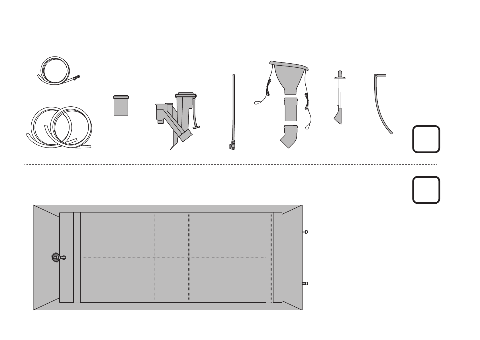
HOMEBIOGAS HBG 4.0 User manual

1
HB4/OM/150221
VERSION 150221
HBG 4.0 HOUSEHOLD BIOGAS SYSTEM
OWNER’S MANUAL
© 2021 HOMEBIOGAS

2
3
5
6
32
34
38
40
44
45
46
Introduction
Safety
System Assembly
Activating the System
Daily Operation
System Care
Troubleshooting
Tech Specs
Homebiogas Fertilizer
Warranty

3
The anaerobic bacteria in the digester
biodegrade the organic waste, producing
biogas in the process.
In addition to biogas, the
system produces a
nutritious, natural fertilizer.
A patented mechanism regulates gas
pressure when the biogas is used, enabling a
steady, even pressure at the end device.
The generated biogas passes through an
active lter to remove any unpleasant odors
and trace amounts of hydrogen sulde, and
is stored in the gas tank.
A special pressure release
mechanism releases excess
gas once the gas tank is lled
to capacity.
Organic waste is fed into
the digester tank, which
is lled with water.
1
2
5
3
4
6
introduction
The HOMEBIOGAS household biogas system turns organic waste like food scraps and animal manure into biogas, which can
be used for cooking, and natural liquid fertilizer, which can be used for gardening.
Biogas is generated in the system by the anaerobic (without oxygen) fermentation of organic matter. Biogas is a ammable
gas that is lighter than air, composed mainly of methane and carbon dioxide.
HomeBiogas is a biological system: performance is aected by environmental conditions and may vary due to physical lo-
cation and ambient temperature.
The system operates as a continuous-ow system: organic waste is fed into one end, and gas
and fertilizer are emitted constantly from the other as long as the system is active and being
fed. (Fertilizer is produced whenever liquid & waste are added into the system)

4
bottom section: digester tank
gas val
ve
gas outlet pipe
biogas lter
f
ertilizer outlet
plunger slot
wast
e inlet sink
plunger & inlet cover
drainage valve
integrated pressure system
main parts of the system

5
safety
c
e
r
t
i
f
i
e
d
5m
GAS
FILTER
20mmø
10mmø
other safety precautions:
No open ames or sparks within 5
meters (15 ft.) from the system.
Purchase and install a safety valve
when using devices indoors.
(Not included in assembly kit)
Biogas is a ammable gas. Always observe these precautions to prevent accidents:
Only use gas tubing with the right
diameter. Contact Homebiogas if
you need more information.
Do not drink the liquid euence.
Use only devices compatible with
or adapted for biogas use. Visit
homebiogas.com/faq to nd out
how to adapt a stove for biogas use.
Dispose of used gas lters safely –
refer to page 39 for details.
Only install system outdoors so ex-
cess gas can be released safely.
Do not place any object on top of
the system.

6
system assembly
1. choose a suitable site 3. install gas pipes & drainage 4. activate system
5. continue feeding &
check for ammable gas
6. initial feeding period
(kitchen waste systems)
2. assemble the system
use system normally!
2 hours 1 hour
wait 1 day
1 - 3 weeks *
2 weeks *
From Assembly to Usage:
Equipment Needed
screwdriver (at) OR
socket wrench 6/7/8 boiling water water (2650 liters) dry sand (96 liters)
Assembly with 2 persons
recommended
*5. continue feeding the system manure as per activation instructions (page 32). you may start trying to light the gas as soon as the gas tank has visibly started to ll
*6. for manure-only systems, there is no initial feeding period and you should continue feeding throughout the activation process (step 5.)

7
site selection & preparation
system should be installed in a
sunny area outdoors for
optimum gas production
system may have mild organic
scent - place away from windows/
doors/outdoors seating
It is important to choose and prepare the right spot for your HomeBiogas system before installation to ensure
optimum performance and avoid potential damage to the system.
Failure to set up the system according to the following instructions could void the HomeBiogas warranty.
make sure the chosen location has
a level surface - usage on sloping or
non-level ground will damage
system
CAUTION: Ensure that the following conditions are met when choosing a location.
The system weighs more than 2600kg when lled and cannot be moved after installation!

8
system should be installed close
to kitchen/cooking area
prepare at least 2.7 x 5.2m space
for the system
(0.5m side, 0.7m front clearance for
maintenance & daily usage)
prepare a rm, at surface clear of
obstructions - do not place on soft
or unstable ground
e.g. at dry ground, tile, concrete
do not place system on shipping
pallets or other weak raised
surfaces
place system within reach of a
water supply
2.5m
4.2m
0.5m
0.5m
0.5m
0.7m

9
system should be installed close
to kitchen/cooking area
prepare at least 2.7 x 5.2m space
for the system
(0.5m side, 0.7m front clearance for
maintenance & daily usage)
prepare a rm, at surface clear of
obstructions - do not place on soft
or unstable ground
e.g. at dry ground, tile, concrete
do not place system on shipping
pallets or other weak raised
surfaces
place system within reach of a
water supply
2.5m
4.2m
0.5m
0.5m
0.5m
0.7m
preparation for gas pipe installation
The system can be connected to a stove/appliance up to 18m away (18m gas tubing provided).
Plan a suitable route for the gas pipe to ensure optimum gas ow and prevent damage to the pipe -
follow detailed instructions for gas pipe installation on page 26, after assembling system.
up to 18m
There should be NO U-shaped bends along the pipe, where
water will collect and block gas ow.
For protection from damage and accidents, you can pass
the pipe underground or elevate it on nearby structures.
Use a rigid pipe to protect the tubing and prevent bends.
It is important to install the pipes at a slight angle from the
system - the lowest point(s) will be used to drain water
collected in the tubes.

10
combined gas tank & digester
plunger overow
clearing rod
10mmø indoor gas tubing, 3m
(20mm connector attached)
gas lter
combined fertilizer & gas outlet
*parts shown in this page are not to scale
20mmø outdoor gas tubing, 2x7m
A
B
gas outlet
connecting pipe
sink & inlet pipe
assembly
combined gas tank + digester (box A)
system parts (box B)

11
combined gas tank & digester
plunger overow
clearing rod
10mmø indoor gas tubing, 3m
(20mm connector attached)
gas lter
combined fertilizer & gas outlet
*parts shown in this page are not to scale
20mmø outdoor gas tubing, 2x7m
A
B
gas outlet
connecting pipe
sink & inlet pipe
assembly
parts bag 2
gas tank sand-packs
bands for 20mmø
gas tubing
band for 10mmø
gas tubing
20mmø gas tube screw connector & tting
20mmø gas
tube straight &
L- connectors 20mm gas tube clamps & stakes
x7
x2 x3
x4
x48
2
drainage kit
2gas tubing T-joint
(20mmø)
ball valve (20mmø)20mmø gas tube
screw connector
& tting
10cm gas pipe
parts bag 1
120mm lip seal rubber ring
(1 spare)
pipe/tubing joint lubricant
x5
LUBRICANT
1

12
back front
(gas, fertilizer out) (input sink, waste in)
i ii
A
HomeBiogas logo is located at the
FRONT end of the system

13
back front
(gas, fertilizer out) (input sink, waste in)
i ii
A
HomeBiogas logo is located at the
FRONT end of the system
i i
ii
ii
iii
i iii
x4
parts bag
1LUBRICANT
LUBRICANT

14
Improper installation of inlet pipe & combined outlet in the HomeBiogas system can damage the digester’s inner liner, causing a leaking digester tank
when lled with water. Follow the steps below to properly insert the pipes, to prevent damage and ensure a functioning system.
check that there is a protective cardboard layer between the
pipe connector openings and the digester’s inner lining. contact
Homebiogas support if this cardboard protector is missing.
i. ii. Lubricate the pipes, align and insert each pipe rmly with the digester on a at,
hard surface. The cardboard protectors will prevent damage to the inner liner.
iii. Combined Outlet Pipe: Hold onto the rim of the pipe connector with
both hands, use the thumbs to push the outlet pipe in all the way
LUBRICANT
Inlet pipe: Hold onto the folds of the digester fabric around the pipe, support the mouth of
the pipe against your body, and push the pipe all the way into the connector. Take care not
to push the pipe against the inner liner!

15
Improper installation of inlet pipe & combined outlet in the HomeBiogas system can damage the digester’s inner liner, causing a leaking digester tank
when lled with water. Follow the steps below to properly insert the pipes, to prevent damage and ensure a functioning system.
check that there is a protective cardboard layer between the
pipe connector openings and the digester’s inner lining. contact
Homebiogas support if this cardboard protector is missing.
i. ii. Lubricate the pipes, align and insert each pipe rmly with the digester on a at,
hard surface. The cardboard protectors will prevent damage to the inner liner.
iii. Combined Outlet Pipe: Hold onto the rim of the pipe connector with
both hands, use the thumbs to push the outlet pipe in all the way
LUBRICANT
Inlet pipe: Hold onto the folds of the digester fabric around the pipe, support the mouth of
the pipe against your body, and push the pipe all the way into the connector. Take care not
to push the pipe against the inner liner!
i
LUBRICANT
1
parts bag
LUBRICANT

16
Inlet sink orientation:
short cord & plunger
slot towards back
long cord
towards front
x2

17
back front
(gas, fertilizer out) (input sink, waste in)
1
1
22
with another person’s help, stretch out
digester inner lining with the 4 corner strings
i ii
Before lling the digester, make sure it is
in a suitable location, chosen according
to the site selection criteria in page 7-8.
The digester must be placed on a
attened, level surface!
Inlet sink orientation:
short cord & plunger
slot towards back
long cord
towards front
x2

18
* pipes must point inwards when lling
* rest hose on digester & enter inlet pipe from opposite side

19
check lled digester for leaks. contact HomeBiogas if
any leaks are seen.
* pipes must point inwards when lling
* rest hose on digester & enter inlet pipe from opposite side

20
ii
i
LUBRICANT x2
Other HOMEBIOGAS Garbage Disposal manuals
Popular Garbage Disposal manuals by other brands

InSinkErator
InSinkErator Badger 1 owner's manual

Green Power
Green Power TDH 00500 instruction manual

OMOIKIRI
OMOIKIRI NAGARE SLIM 500 OPERATING AND INSTALLATION Manual

Vogue
Vogue VGWD34 Series Owner's Manual & Installation Instructions

Mistral
Mistral Ultra 10504 Specifications

Crommelins
Crommelins CC40HP Operation & instruction manual