HomePlus ClearPlus Premium Series User manual

OWNER’S MANUAL & INSTALLATION GUIDE
ClearPlus™ Premium Series Tannin & Organics ilters
APPLICABLE MODELS: CPT-5810SXT Series
PLEASE READ THIS MANUAL CARE ULLY BE ORE
ATTEMPTING INSTALLATION. AILURE TO OLLOW THESE
INSTRUCTIONS MAY A ECT THE PER ORMANCE O YOUR
SYSTEM, VOID YOUR WARRANTY, AND RESULT IN
PROPERTY DAMAGE.

2
Congratulations on the purchase of your ClearPlus™ Premium Series tannin and
organics filter.
You have purchased one of the finest water treatment systems on the market today. This
manual is designed to provide owners, installers, and service technicians with detailed
information about the installation, start-up, and operation of your new water treatment
system.
The brain of your ClearPlus™ system is the leck 5810SXT control valve. It is manufactured
by one of the world’s premier water treatment companies. The leck 5810 control valve is
well respected for its reliability, serviceability, simple operation, and value. The integrated
leck SXT digital valve controller offers unsurpassed simplicity of operation, yet complete
control over all important valve operations. The Pentair leck 5810SXT Downflow/Upflow
Service Manual is also included with your system. It includes additional information
regarding the operation of your valve, replacement parts lists, and more.
Your ClearPlus™ water treatment system is designed to offer low maintenance operation.
The control valve will perform regular backwash functions automatically, however, you will
need to periodically add salt to your brine tank as it is consumed by the system. or your
convenience, your system has been pre-programmed for you at our factory. Should you
need to change any of the settings, simply follow the instructions provided in this manual.
IMPORTANT SA ETY SYMBOLS
Hazards or unsafe practices that may result in personal injury
and/or severe property damage.
Hazards or unsafe practices that may cause operational
problems with your water treatment system.

3
Table of Contents:
GENERAL WARNINGS ……………………………………………………………………………………………...….. …….. 4
OPERATING CONDITIONS …………………………………………………………………………………………….…... 5
INSTALLATION ………………………………………………………………………………………………………….…..…..….. 7
Step 1 – Pre-Installation Inspection ……………………………………………………………..……… 7
Step 2 – Selecting an Installation Location ………………………………………………..…..... 8
Step 3 – Prepare Treatment Tank ………………………………………………………………..……… 10
Step 4 – Turn off the Water & Electric Water Heaters ………………………………….… 12
Step 5 – Prepare and Install Inlet and Outlet Plumbing Connection …….…… 13
Step 6 – Drain Line Installation …………………………………………………………………………..… 15
Step 7 – Brine Tank Connections ………………………………………………………………………… 16
Step 8 – Connect the Brine Tank Overflow to Drain .……………………………………… 18
Step 9 – Control Valve Set-up ………………………………………………….………………………..….. 19
Step 10 – Initial Start-up and Leak Testing ………………………………………………….....…. 20
REGENERATION ………………………………………………………………………………………………………….…..……. 23
SALT ……………………………………………………….……………………………………………………………………….….…… 25
CHANGING TIME O DAY ………………………………………………………………..…………………………..…… 26
USER PROGRAMMING MODE ……………………………………………………………………………………..…. 26
MASTER PROGRAMMING MODE ………………………………………………………………………….……..… 29
RESETS ……………………………………………………….…………………………………………………………………….…… 30
OPERATION DURING A POWER AILURE ………………………………………………………….…..…… 31
DIAGNOSTIC DATA …………….……………………………………………………………..…………………………..…… 31
MAINTENANCE & TROUBLESHOOTING ……………………………………………………….…..….……. 32
WARRANTY IN ORMATION ………………………………………………………………………………………..…… 35

4
GENERAL WARNINGS
Do not allow children or pets to play on or around the water filter.
Do not install or store this filter system where it will be exposed to freezing temperatures.
Do not tamper with controls.
Do not repair, replace, or attempt to service any part of the system unless specifically
instructed to in this manual and you have the understanding, tools, and skills necessary to
carry out the procedure.
Packing materials can be dangerous to children. Keep all packing material (plastic bags,
polystyrene, boxes, etc.) well out of the reach of children.
Individual components of this water treatment system, and the installed system, are heavy.
Precautions should be taken to prevent personal injury or strain. Do not move heavy
components without assistance if you are not physically capable of safely carrying out the
procedure.
If the water treatment system is to be left unattended for an extended period of time
(vacation, etc.), we strongly recommend that you turn off the water supply to the system, or
the whole house, while you are away.
All state, provincial, and local government codes governing installation of water softeners
should be observed.
If your water pipes are metal (galvanized or copper), they may be used to ground electrical
systems, appliances, or your phone line. If this is the case, be sure to install regulation
ground clamps to the metal pipe on each side of the control valve and connect a jumper
wire between the 2 clamps (#4 gauge solid copper wire recommended). Consult a certified
electrician or plumber if you are unsure.

5
OPERATING CONDITIONS
The following chart provides guidance on the conditions required for successful operation of
your ClearPlus™ system.
USE O THIS EQUIPMENT OUTSIDE O THESE OPERATING CONDITIONS MAY
ADVERSELY A ECT THE PER ORMANCE O YOUR SYSTEM, RESULT IN SYSTEM
DAMAGE INCLUDING WATER LEAKS AND CORRESPONDING PROPERTY DAMAGE, AND
MAY VOID YOUR WARRANTY.
Minimum Water Pressure 20 PSI
Maximum Water Pressure 90 PSI*
Recommended Water Pressure 40-70 PSI
Water Temperature 36 to 100 (2 to 38C)
Air Temperature 32 to 125 (0 to 52C)**
pH Range 6.0*** to 9.0
Maximum Total Organic Carbon (TOC) 10 ppm (mg/l)
Maximum Tannins 5 ppm (mg/l)
Maximum Recommended Iron <0.3 ppm (mg/l)
Maximum Recommended Manganese <0.05 ppm (mg/l)
* While the ClearPlus™ system is built to withstand pressures exceeding 90 PSI, if your water
pressure is greater than 70 PSI, we recommend that you have a certified plumber install a
pressure reducing valve ahead of the ClearPlus™ system.
** The system cannot be subjected to freezing conditions or severe damage to the system
and your property could occur.
*** pH correction is strongly recommended where pH levels are less than 6.5 to prevent
damage to your control valve and plumbing system, and to prevent leaching of metals from
copper and brass plumbing components and solder in your home. Contact your dealer for
recommendations.

6
ClearPlus™ 5810SXT Series Tannin & Organics ilter, Specifications low Rates &
Backwash Requirements:
Model
9-48 10-54 12-52 13-54 14-65
Lbs of Salt Per Regeneration
@ dose of 10 lbs/C : 10 15 20 25 30
Resin Volume
(Cubic eet): 0.75 1.25 1.5 2 2.5
Neutralizing Media Volume
(Cubic eet): 0.25 0.25 0.5 0.5 0.5
Total Media Volume
(Cubic eet): 1 1.5 2 2.5 3
Optimal Service low Rate*
(GPM)
2.5 4.5 5.5 7 9
Maximum Service low*
Rate (GPM)
4 6.5 7.5 10 12.5
Backwash low Rate at 40
Water Temp (GPM)
2.5 3 4 5 5.5
Backwash low Rate at 70
Water Temp (GPM)
2.7 3.5 4.5 5.5 6
* or the best performance of your system, the optimal service flow rate should not be
exceeded on a continuous basis. Satisfactory to good performance can generally be
achieved up to the recommended maximum service flow rate as long as this level of flow
rate is not sustained continuously.
CON IRM THAT YOUR WATER CONDITIONS, SERVICE LOW RATE NEEDS, AND
AVAILABLE BACKWASH LOW RATES MEET THE ABOVE SPECI ICATIONS OR THE
MODEL YOU ARE INSTALLING BE ORE COMMENCING THE INSTALLATION PROCESS.
I IN DOUBT, CALL YOUR DEALER OR ADVICE. INSTALLED UNITS CANNOT BE
RETURNED.

7
INSTALLATION
WE RECOMMEND THAT YOU READ THIS ENTIRE MANUAL BE ORE STARTING THE
ACTUAL INSTALLATION. WHILE WE STRONGLY RECOMMEND THAT A LICENSED
PLUMBER PER ORM ALL INSTALLATION WORK, A MECHANICALLY-INCLINED
HOMEOWNER WITH SUITABLE PLUMBING KNOWLEDGE CAN INSTALL THIS SYSTEM.
IN ALL CASES, IT IS CRITICAL THAT THE INSTALLATION BE DONE IN ACCORDANCE
WITH THESE INSTRUCTIONS AND ALL APPLICABLE PLUMBING AND ELECTRICAL
CODES. BE SURE TO OBTAIN ALL REQUIRED PERMITS. I THESE INSTRUCTIONS AND
THE APPLICABLE CODES ARE IN CON LICT, THE RELEVANT PLUMBING/ELECTRICAL
CODE SHALL BE OLLOWED. EQUIPMENT AILURE, PERSONAL INJURY, OR PROPERTY
DAMAGE CAN RESULT I THIS EQUIPMENT IS NOT INSTALLED PROPERLY.
Step 1. – Pre-Installation Inspection
Inspect all of the components that you received with your unit. You should have received the
following:
1. leck 5810 SXT Control Valve
2. Media Tank
3. Upper Screen
4. Bypass Assembly w/ Bypass Valve and 1” NPT Connector Yokes (2)
5. Riser tube and Lower Distributor
6. Bag or Box of Gravel
7. Bag(s) or Box(es) of Resin/Media (2 Types)
8. Drain Line low Control - DL C (attached to #1)
9. Brine Tank with Brine Well, Brine Valve assembly, Salt Grid, and Overflow Elbow
10. Brine Tubing (10 feet)
11. unnel
12. Small Parts Bag (contains food grade silicone O-ring lubricant, and parts for the brine
tubing connections)

8
Step 2. – Selecting an Installation Location
While exterior installation in warm climate areas is possible, we strongly recommend interior
installation only. The system cannot be allowed to freeze or severe system damage could
occur. The system should not be exposed to rain and it should not be installed in direct
sunlight, as long-term exposure to UV light could damage components of the system.
urthermore, direct sunlight could raise the internal water temperature in the treatment tank
and reduce backwash effectiveness.
In most cases, the system should be located A TER your water pump and pressure tank,
A TER the branch line to exterior irrigation, and BE ORE your hot water heater.

9
I YOU HAVE OTHER WATER TREATMENT EQUIPMENT, YOU SHOULD DISCUSS THE
ORDER O YOUR TREATMENT EQUIPMENT WITH YOUR DEALER PRIOR TO
INSTALLATION.
Select a location for installation of your water filter that is within close proximity to the main
incoming water line of the home. The location should have a firm, level surface with enough
space for the unit itself including the brine tank and sufficient space surrounding the unit to
facilitate maintenance. We recommend that the brine tank be located immediately beside
your treatment tank and control valve (it can be beside or in front). requent access to the
brine tank is necessary to add salt so it should be located in a readily accessible location.
Although not ideal, if it is necessary, the brine tank can be located up to about 10 feet away
from the treatment tank and control valve (max. tubing length).
WHILE WATER LEAKS ARE VERY RARE AND UNEXPECTED, YOUR WATER ILTER
SYSTEM SHOULD BE LOCATED NEXT TO A LOOR DRAIN OR PROTECTED BY A WATER
LEAK DETECTION SYSTEM WITH AUTOMATIC SHUT-O VALVE TO PREVENT WATER
DAMAGE TO YOUR PROPERTY IN THE UNLIKELY EVENT O A WATER LEAK.
RECOMMENDED WATER LEAK DETECTION SYSTEMS ARE AVAILABLE AT WWW.A-LEAK-
DETECTOR.COM.
You will also require a suitable drain to discharge waste water from the backwash cycle. A
drain standpipe for a washing machine, floor drain, or sump pump are excellent drain
options. We recommend that the drain line be connected to a minimum 1½" drain
standpipe or floor drain located ideally below the top of the head of your water filter. If
possible, the drain should be no farther than 20 feet from the system.
NOTE: NEVER CONNECT THE DRAIN LINE DIRECTLY INTO A DRAIN PIPE. ALLOW AN AIR
GAP BETWEEN THE DRAIN TUBING AND WASTE LINE TO PREVENT THE POSSIBILITY
O BACK-SIPHONING. WE DO NOT RECOMMEND USE O A CHECK VALVE AS IT MAY
BECOME CLOGGED WITH CONTAMINANTS EJECTED ROM THE SYSTEM DURING
BACKWASH.

10
You will also need access to a standard, non-switched, grounded 120 volt (60 Hz) electrical
outlet. An extension cord may be used to reach a suitable electrical outlet. If this option is
used, ensure that the extension cord is UL/CSA certified and of an appropriate wire gauge
for the application.
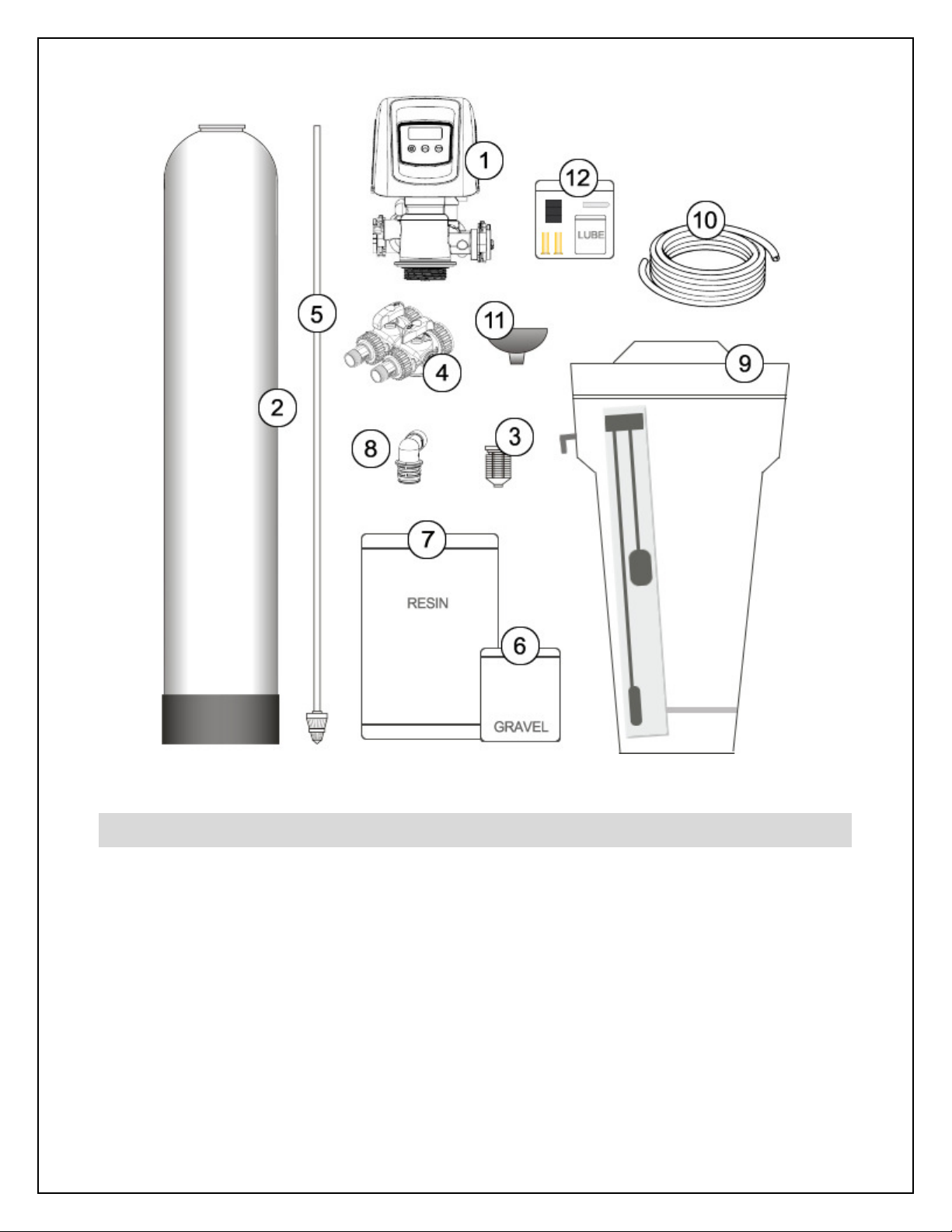
Step 3. – Prepare Treatment Tank
Three types of media are supplied with your system: gravel which forms the base layer
(underbedding) in your treatment tank, a neutralizing media that looks like crushed white
rock, and an anion exchange resin (small wet white plastic beads) which removes tannins
and organics from the water.
Place the tank in the location where it will sit when the installation is complete. Note that the
black base of your tank is not permanently attached to the rest of the tank. If your tank
appears to be crooked, the base has likely been knocked out of alignment during shipping.
This can be correct by picking the tank up and tapping it on a hard surface while holding it
perpendicular to the floor. A few light taps will generally straighten it out.
Temporarily remove the distributor and riser tube assembly from the treatment tank. Hand
tighten the leck 5810SXT control valve on the tank and mark where the front of the tank will
be. Turn the tank so that the front of the tank is where you want it when it is full – once it is
full of media and water, it becomes very heavy and difficult to move!
Remove the control valve and re-insert the distributor and riser tube assembly into the tank.
The distributor, which looks like a cone-shaped plastic screen, is pre-connected to the end of
the long plastic riser tube which extends from the bottom of the tank to the top of the tank
where the control valve is attached. At the bottom of the tank, there is a recess in the center
of the tank to accept the distributor to keep it properly aligned. The riser tube has been pre-
cut to the correct height for you. When the distributor is correctly positioned, the top of the
riser tube will be approximately 1/8 to 1/4 of an inch below the top of the tank. If the tube is
flush or protruding above the top of the tank, the distributor tube is not nested correctly in the
recess at the bottom of the tank.
Add enough water to the tank to cover the lower distributor with a minimum of 6 inches of
water. This will prevent damage to the lower distributor as gravel is loaded. Place the funnel
into the tank so that the riser tube is in the middle. Place tape over the open end of the riser
tube. This will prevent gravel or media from accidentally going down the tube during the
following steps.

11
or the following steps, we recommend that you wear a dust mask. Take the bag/box of
gravel and, using a small scoop, add the gravel to the tank through the funnel to completely
cover the lower distributor. Use all of the gravel. Be sure to provide some downward
pressure on the riser tube while adding the gravel to ensure that the distributor does not shift
out of its recess or rise up. Ensure that you create an even layer of gravel across the bottom
of the tank. A rigid piece of thin wall tubing (conduit, copper pipe, etc.), approximately 1”
longer than the tank height works well as a leveling tool if you need it. Ensure that the riser
tube remains centered in the opening at the top of the tank.
Once this is complete, add the neutralizing media in the same manner, and then the anion
resin. Use all of the media provided. Depending on the capacity of the system, there will
only be enough resin to fill the tank to about 1/2 to 3/4 full. This is normal. The media tank
should never be filled to the top of the tank as the remaining space, known as the
“freeboard,” is necessary for the media to have room to expand during the backwash cycle.
Once you have finished adding the media to the tank, remove the tape from the distributor
tube. Be careful not to pull upwards on the riser tube while doing this as it is important that
the distributor remain in its recess at the bottom of the tank.
ill the media tank with water up to within a couple of inches of the top of the tank.

12
Attach the upper screen to the underside of the control valve.
Be sure to twist clockwise and lock it into place.
Apply a small amount of lubricant to the top inch of the outside
of the riser tube and to the tank o-ring seal.
Note: Only use food-grade silicone lubricant. A small bag of
lubricant is provided in the small parts bag. Do NOT use
petroleum jelly.
The control valve can now be secured to the top of the tank.
Before attaching the valve, check to make sure that there is no
debris such as gravel or resin in the tank threads. Screw the
control valve onto the tank – make sure that the riser tube inserts
into the center hole in the upper screen and the control valve as
you screw down the valve. The control valve should be hand-tightened (clockwise). Do
NOT use the control valve's timer assembly for leverage and do not use tools. A firm grasp
with both hands at the base of the valve will work. Do NOT use pipe cement (“pipe dope”) or
Teflon® tape on the threads.
Step 4. – Turn off the Water & Electric Water Heaters
AILURE TO OLLOW THIS PROCEDURE COULD RESULT IN SERIOUS, PERMANENT
DAMAGE TO THE HEATING ELEMENTS IN YOUR WATER HEATER.
If you have a conventional electric water heater or an on-demand (tankless) electric water
heater, we highly recommend that you turn off the power to the heater while installing any
water treatment equipment. Turn off power to your water heater now.
Turn off the household main water shutoff valve. Open several plumbing fixtures inside the
home as well as the outside faucets to drain as much water out of the plumbing system as
possible.
ollowing completion of the entire installation, restore the water flow by turning on the
household main water valve and allow all air to be purged from the plumbing system before
turning the power back on to your water heater.

13
Step 5. – Prepare and Install Inlet and Outlet Plumbing Connections
TE LON® TAPE IS THE ONLY SEALANT TO BE USED ON THE 1” NPT CONNECTOR
YOKES AND DRAIN ITTINGS.
I YOU WISH TO USE COPPER PIPING OR YOUR INSTALLATION AND WILL BE
SOLDERING THE JOINTS, DO NOT APPLY HEAT NEAR YOUR CONTROL VALVE, BYPASS
ASSEMBLY, 1” NPT CONNECTOR YOKES, OR THE DRAIN ITTINGS; OTHERWISE
SERIOUS DAMAGE TO THESE PARTS COULD OCCUR. ALWAYS SOLDER JOINTS WITH
THESE COMPONENTS DETACHED. I YOU ARE USING COPPER ADAPTERS TO
CONNECT TO THE 1” NPT CONNECTOR YOKES, IT IS RECOMMENDED THAT YOU
SOLDER A 6" PIECE O COPPER PIPE INTO EACH O THE CONNECTION ADAPTERS
AWAY ROM THE VALVE, THEN LET THEM COOL O BE ORE THREADING THEM ONTO
THE 1” NPT CONNECTORS.
Key Control Valve Components:
1. Control Valve Body
2. Bypass Valve
3. 1” NPT (Male) Connector Yokes
4. Drain Line low Control (DL C)
5. Valve Cover
6. DL C Retention Clip
The system’s control valve is connected to
your incoming and outgoing water lines by
way of a bypass assembly with 1”NPT threaded
fittings. This assembly is composed of the
bypass valve and two 1”NPT connector yokes.
Locate the inlet and outlet ports on the back of the control valve. Note that the inlet and
outlet are marked with arrows indicating the correct direction of water flow. When you are
looking at the back of the control valve, the inlet is on the left and the outlet is on the right.
Check the corresponding markings on the bypass to ensure the correct direction of water

14
flow and attach the bypass valve to the control valve. The in and out arrows on the bypass
should be pointing the same direction as the in and out arrows on the outside of the control
valve.
BE VERY CARE UL TO MAKE SURE YOU PLUMB THE SYSTEM IN THE RIGHT DIRECTION.
The bypass assembly is secured to the control valve using threaded fittings. Thread sealant
tape should not be used on these threads. The seal is made by way of o-rings. To attach
the bypass to the control valve, simply thread the 2 nuts on the bypass onto the valve until
the nuts bottom out on the valve body. Do not overtighten - it is normal for some “play” to
exist when the bypass assembly is properly seated. This allows for minor misalignment of
the piping connections and relieves stress on the valve. The 1” NPT connector yokes are
connected to the bypass in the same manner (they are normally shipped to you pre-
connected to the bypass, but you can separate them to make the plumbing to your main
water lines easier if you want).
You will need to purchase the appropriate NPT threaded fittings to connect the connector
yokes to the material and size of your main inlet and outlet water lines.
Plumb your main incoming and outgoing water lines using suitable pipe, fittings, elbows, etc.
as necessary to create a tidy, secure installation up to the back of the bypass valve
(including the correct connection adapters to mate with the threaded fittings on the bypass
assembly’s connection yokes.) Be sure to follow all local plumbing codes.
WE HIGHLY RECOMMEND
THAT YOU REMOVE THE
BYPASS ASSEMBLY ROM
THE CONTROL VALVE BE ORE
MAKING THESE INAL
CONNECTIONS AS YOU MAY
INADVERTENTLY APPLY TOO
MUCH PRESSURE ON THE
VALVE WHILE SECURING THE
ADAPTERS, CAUSING DAMAGE
TO THE VALVE BODY.

15
Place the bypass in the “bypass” position as pictured above.
Step 6. – Drain Line Installation
NOTE: NEVER CONNECT THE DRAIN LINE DIRECTLY INTO A DRAIN. ALLOW AN AIR-GAP
O A MINIMUM O 1 INCH (CHECK LOCAL CODES) BETWEEN THE DRAIN LINE AND
WASTE LINE TO PREVENT THE POSSIBILITY O BACK-SIPHONING. ALWAYS OLLOW
LOCAL CODES. THE DRAIN LINE SHOULD NOT BE EXPOSED TO REEZING
TEMPERATURES.
During the regeneration cycle, your ClearPlus™ system will send water and contaminants
out the drain port. This port needs to be connected to a suitable household drain, ideally
within 20 feet of your media tank. A nearby floor drain, sump pump, or a standpipe for a
washing machine is an excellent option. We recommend that the drain line be connected to
a minimum 1½" drain standpipe or floor drain located ideally below the top of the head of
your water filter.
Locate the drain port on the back of your control valve. The drain line flow control assembly
(DL C) is pre-attached to the control valve - it has black plastic housing with 3/4 inch male
NPT threads.
You will need to purchase suitable pipe or tubing for the drain line. The minimum drain line
diameter is 1/2 inch although 3/4” is preferred. Polyethylene tubing, PEX, PVC, CPVC, and
copper pipe are all acceptable material choices for the drain line. If you are using flexible
tubing, be sure that there are no “kinks” or “crimps” in the tubing after installation that may
cause a flow restriction. If used, overhead drain lines are not to exceed a height of 5 feet
above the control valve and should be not more than 50 feet in length. Should an overhead
drain line be utilized, it is recommended that the drain line diameter be not less than 3/4”,
and that it not be fastened flush to the bottom of a floor joist to minimize noise transfer to the
upstairs of the building during regeneration.
Using an appropriate fitting, connect the drain line flow control to your drain line
tubing/pipe. The DL C can be removed from the control valve to facilitate easier
plumbing if desired. To remove the drain line flow control, pull on the retaining clip to
remove it and then grasp the drain line flow control and pull upward. You may wish to dry-fit

16
the fitting first to make sure you line up the drain line properly with the drain port on the
control valve if you are using rigid pipe.
Re-insert the DL C into the control valve and securely lock into place with the retaining clip
when done.
Ensure that the drain line is thoroughly secured along its route to the drain. The drain line
will be under pressure when the backwash cycle is working. If not adequately secured, the
drain line could vibrate during backwash causing excessive noise. If this is experienced, use
additional fixtures to better secure the drain line.
Step 7 – Brine Tank Connections
To complete the connection of the control valve to the brine tank, you will require the black
brine tubing and numerous parts from the small parts bag. We recommend that the brine
tank be located as close as possible to the treatment tank and control valve, however, it can
be up to 10 feet away if necessary.
Locate the brine port on the right side of your leck 5810 control valve (when facing the front
of the control valve).
1. Brine Tank Lid
2. Brine Valve
3. Safety loat
4. Air Check Valve
5. Salt Grid
6. Brine Overflow Elbow
7. Brine Tubing

17
1. Make sure that the end of the brine tubing is cut square and that the tubing coating is
smooth, unmarred, and undamaged.
2. Slide the G N compression nut onto the end of the brine tubing with the open end
facing the end of the tubing.
3. Insert the brass tubing insert into the end of the brine tubing.
4. Insert the filter screen into the brass insert.
5. Center the tubing on the brass brine port on the control valve and thread the G N
compression nut onto the brine port (clockwise). Securely tightly. Excessive forced is
not required and should not be used.
Remove the lid off the top of the brine tank.
Look inside your brine tank and you will see
a vertical white tube called the brine well.
Remove the cap from the top of the brine well.
Inside the brine well, you will find the brine valve
with air check and safety float. The other end of
the brine tubing connects to the top of the brine
valve in the same manner as the connection to
the brine port on the control valve except there is
no filter screen. There is a small hole drilled in the
brine tank and brine well that you insert the brine
tube through to connect it to the brine valve. eed a small length of brine line through this
hole and connect it to the brine valve assembly using a brass insert and the existing plastic
G N compression nut that is attached to the brine valve.

18
If you have an excessive length of brine line, you should trim it to a more appropriate length
first. The brine tubing should be as short and straight as possible. Make sure that the end of
the brine tubing is cut square and that the tubing coating is smooth, unmarred, and
undamaged. Tighten the black compression nut finger tight, then confirm that there are no
kinks or crimps in the brine line.
Step 8 – Connect the Brine Tank Overflow to Drain
Locate the plastic overflow elbow on the side of your brine tank. This is a safety overflow that
will allow water to be safely carried to a drain in the event that the system attempts to overfill
the brine tank AND the brine tank safety float fails. It should be connected to a suitable drain
if an overflow would not immediately and safely run down a floor drain on its own.
You may use the same material as was used to plumb your drain line connection from the
control valve or other suitable material. 1/2 inch I.D. vinyl tubing is a popular option, but you
need to ensure that this material cannot become kinked or crimped.
This drain line will not be under pressure, so it must be directed to a drain that is physically
lower than it is. DO NOT connect this drain line into the pressurized drain line coming from
the control valve. It must be run separately to the drain. Be sure to leave a 1” air gap at the
drain to prevent back-siphon. This is only a safety overflow drain and will not be in use under
normal operation. Depending on your installation, running the drain tubing to an open
basement floor drain is often possible. Secure the drain tubing to the elbow with a suitable
fitting or hose clamp.

19
Step 9 – Control Valve Set-up
During cold weather, the control valve should be warmed to room temperature before
operating. Note: All electrical connections must be done according to local codes.
Plug the control valve into a standard, grounded 120 volt (60 Hz) electrical outlet. Be certain
that the outlet is uninterrupted and not controlled by a switch. An extension cord may be
used to reach a suitable electrical outlet. Ensure that the extension cord is UL/CSA certified
and of an appropriate wire gauge for the application. Plug the other end of the power cord
into the electrical port on the control valve.
Note: The electrical port on the control valve is located
on the right side of the valve (when you are facing the
control panel), just behind the tab used to remove the
valve cover. It is a bit tricky to find.
Once plugged in, the digital display on the control
valve will illuminate. The control valve may need to
reset to the home position when it is powered up.
If it does, the motor will run for a few seconds.

20
The digital display should be alternating between the current time setting (which is probably
incorrect), and the number of gallons remaining until the next regeneration cycle. You will
also see the “service” icon which appears as a small faucet in the bottom left corner of the
display window.
We will first set the time of day to the correct time. Press either the UP or DOWN button and
hold for a few seconds. The parameter display will read “TD” (Time of Day) and the
“programming” mode icon will appear (4 dots and a pencil). Use the UP and/or DOWN
buttons to change the time displayed to the correct time of day. Once the display shows the
correct time, press the EXTRA CYCLE button to save your changes.
Your system has been pre-programmed to regenerate based on its capacity and your water
conditions, and to perform this process at 12:30am in the morning when it is unlikely that
water will be required in the building. In most cases, this will occur every 5 to 7 days, but this
will vary depending on your water conditions and water demand. If water is required during
the regeneration process, untreated water will be permitted to flow to meet your service
needs. You can alter the time of day that the regeneration process occurs if 12:30am is not
ideal for you. If you have another automatic backwashing/regenerating water treatment
system, make sure that they are not set to regenerate at the same time. We recommend
that they backwash/regenerate at least 2 hours apart. ollow the instructions under “User
Programming Mode” to change the regeneration time if desired. If you want to change the
duration of the regeneration cycles, these settings must be edited in the “Master
Programming Mode” – see below for details.
Before proceeding, you will need to confirm or set your feed water organics level setting and
your day override setting. In most cases, these settings will have been pre-programmed for
you at the factory if we were given information about your water source and quality at your
time of purchase. See “User Programming Mode” below for instructions on how to do this.
Step 10 – Initial Start-up and Leak Testing
Make sure the white salt grid is correctly positioned at the bottom of the brine tank.
This manual suits for next models
1
Table of contents
Other HomePlus Water Dispenser manuals

HomePlus
HomePlus SP-5810XTR2-8-44 Troubleshooting guide

HomePlus
HomePlus MultiSoft Premium EMS-5810SXT Series Troubleshooting guide

HomePlus
HomePlus SoftPlus SP-5800XTR2 Series Troubleshooting guide

HomePlus
HomePlus SoftPlus SP-5810XTR2 Series Troubleshooting guide

HomePlus
HomePlus SoftPlus SP-5800SXT Series Troubleshooting guide