Homewerks.com 3
SAFETY INFORMATION
Please read and understand this entire manual before attempting to assemble, operate or install the product.
• Always disconnect the power supply prior to servicing the fan,
motor or junction box.
• Follow all local building, safety and electrical codes as well
as NEC (National Electrical Code) and OSHA (Occupational
Safety and Health Act).
• Electric Service supply must be 120 volts, 60 hertz.
• This product must properly connect to the grounding
conductor of the supply circuit.
• Do not bend or kink the power wires.
• Do not install in a ceiling with insulation greater than R40.
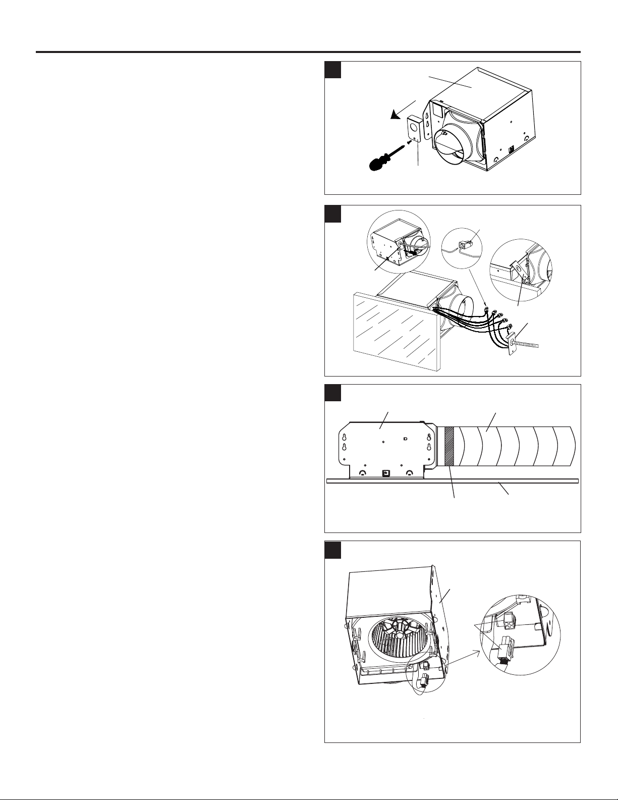
• Duct work should be installed in a straight line with minimal
bends.
• Duct work size must be the same size as the discharge and
should not be reduced. Reducing the duct size may increase
fan noise.
• This product is not intended for connection to rigid metal
conduit. For use with exible conduit only.
WARNING: To reduce the risk of re, electric shock,
or injury to persons, observe the following:
1. Use this unit in the manner intended by the manufacturer.
If you have any questions, please call customer service.
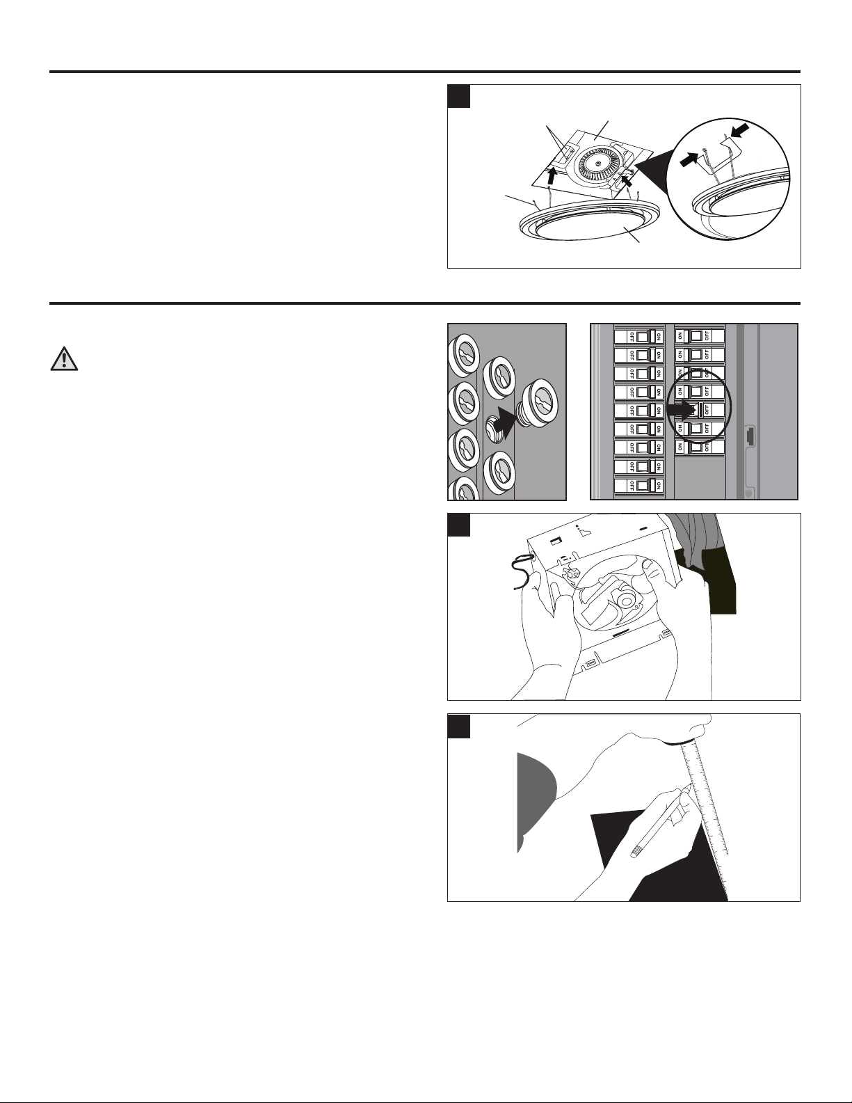
2. Before servicing or, cleaning the unit, switch the power off at
the service panel and lock the service disconnecting means to
prevent the power from being switched on accidentally. When
the service disconnecting means cannot be locked, securely
fasten a prominent warning device, such as a tag, to the
service panel.
3. Installation work and electrical wiring must be done by a
qualied person(s) in accordance with all applicable codes
and standards, including re-rated construction.
4. Sufcient air is needed for proper combustion and exhausting
of gases through the ue (chimney) of fuel burning equipment
to prevent backdrafting.Follow the heating equipment
manufacturer´s guideline and safety standards such as those
published by the National Fire Protection Association (NFPA),
and the American Society for Heating, Refrigeration and Air
Conditioning Engineers (ASHRAE) and local code authorities.
5. When cutting or drilling into the wall or ceiling, do not damage
electrical wiring and other hidden utilities.
6. To reduce risk of re and to properly exhaust air, be sure to
vent air to the outdoors. Do not vent exhaust air into spaces
within walls or ceilings, or into attics, crawl spaces, or
garages.
7. If this unit is to be installed over a tub or shower, it must be
marked as appropriate for the application and be connected to a
GFCI (Ground Fault Circuit Interruptor)-protected branch circuit.
8. This ventilation fan is intended to be installed at least
3 ft. 3-1/4 in. (1 m) from the showerhead when installing over
a bathtub or shower. Installation within a shower stall is not
recommended for this unit, unless the 3 ft. 3-1/4 in. (1 m)
distance can be met.
CAUTION
• For general ventilating use only. Do not use to
exhaust hazardous or explosive materials and
vapors.
• Not for use in kitchens.
• To reduce the risk of injury to persons, install the
fan at least 7 feet (2.1m) above the oor.
• To reduce risk of re and to properly exhaust air,
be sure to vent air to the outdoors. Do not vent
exhaust air into spaces within walls or ceilings,
or into attics, crawl spaces, or garages.
CAUTION: Installation of this unit requires the power to be OFF until installation is complete. If you encounter issues with the unit not
powering up, please review the troubleshooting section of the instruction manual.
If you require additional assistance, please call 1-877-319-3757, 7:30 a.m. - 4:30 p.m., CST, Monday - Friday. DO NOT RETURN
TO STORE.
PREPARATION
Before beginning assembly of product, make sure all parts are present. Compare parts with package contents
list and hardware contents. If any part is missing or damaged, do not attempt to assemble, install or operate
the product. Contact customer service for replacement parts at 1-877-319-3757, 7:30 a.m. - 4:30 p.m., CST,
Monday - Friday.
Estimated Assembly Time: 60 minutes
Tools Required for Assembly (not included): Hammer, Flathead Screwdriver, Wood Screws, Duct Tape, Phillips
Screwdriver, and Utility Knife or Drywall Saw
Helpful Tools (not included): Electric Drill, Drill Bits
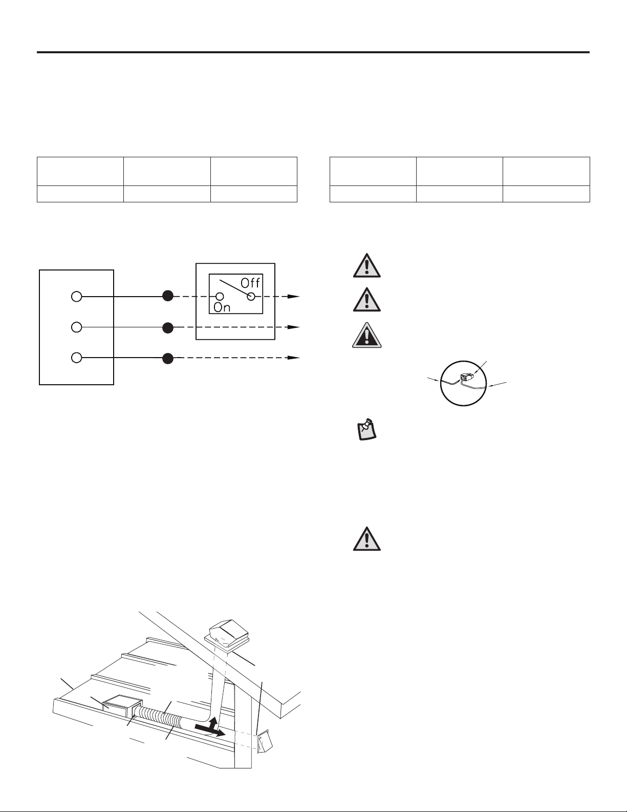
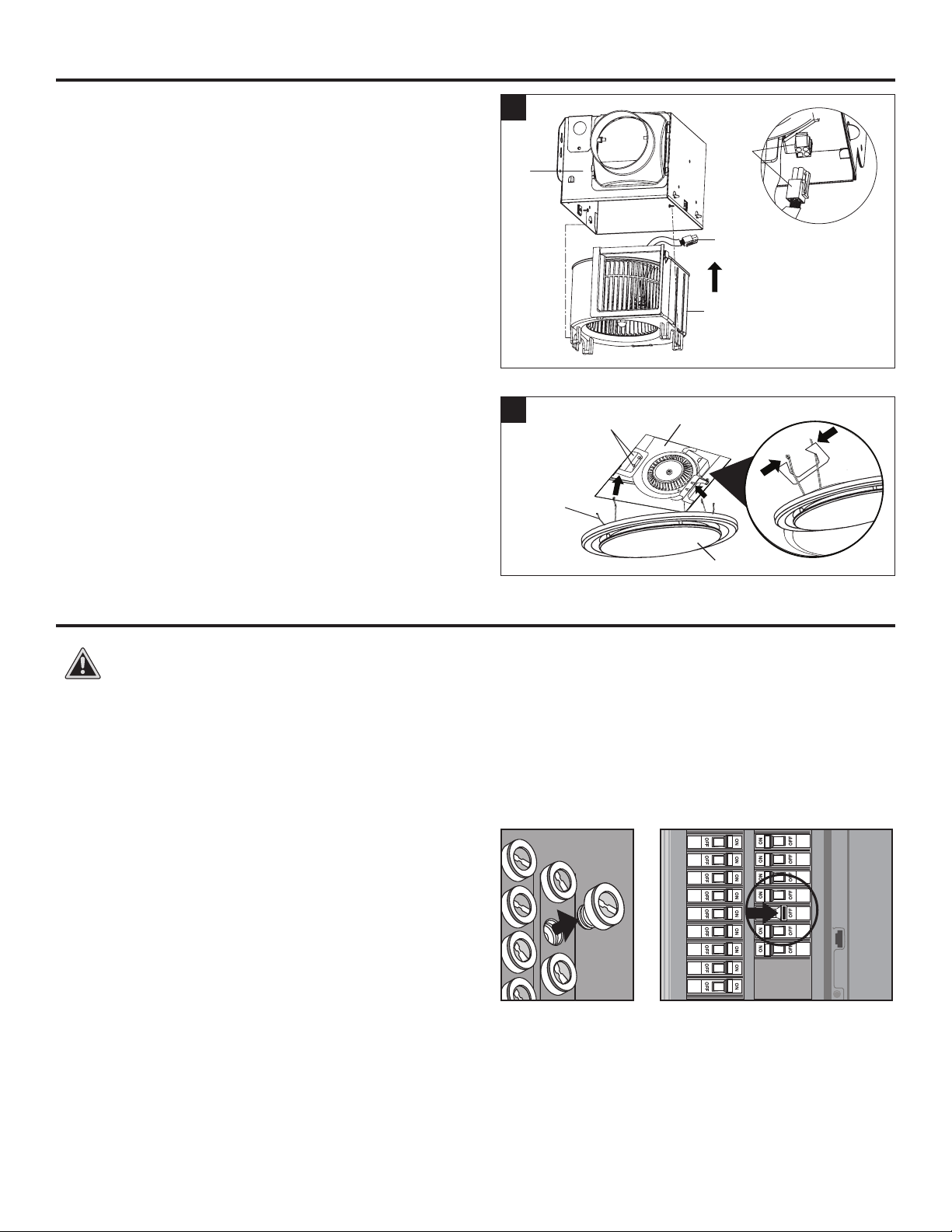
WARNING: RISK OF ELECTRIC SHOCK! Ensure the electricity to the wires you are working on is shut
off. Either remove the fuse or turn off the circuit breaker before removing the existing bath fan or in-
stalling the new one.
Before removing your current ventilation fan, verify the wall switch box has the required wires
necessary for this installation. These supply wires are power (black) and neutral (white), as shown
in the wiring diagram below. If you do not see both of these wires, consult a licensed electrician.