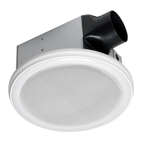
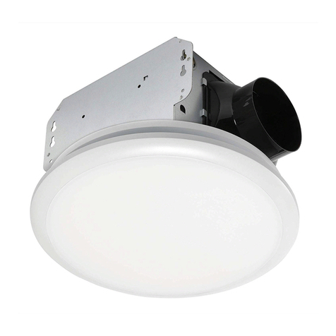
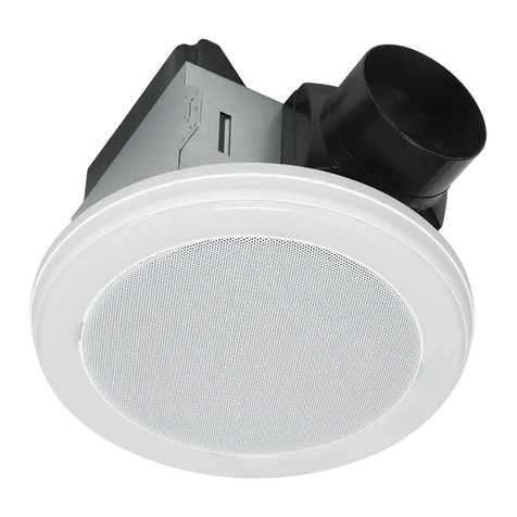
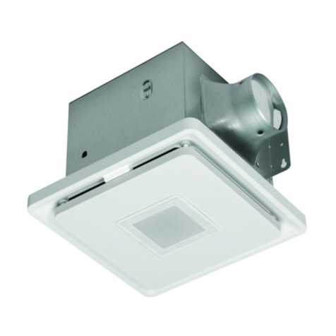
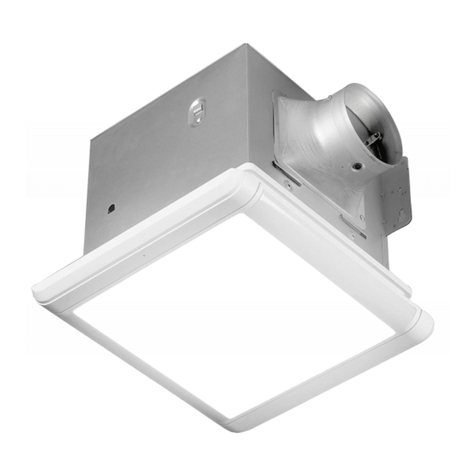
Homewerks HTR-REV02-L User manual

Instructions
www.homewerksww.com Eective/Rev. date: March 15, 2012 1
Model #HTR-REV02-L Item# 398999
Ventilating Bath Fan with
Heater and Light
READ AND SAVE THESE INSTRUCTIONS:
Please read these instructions carefully before attempting to install, operate or service the
ventilating fan. Failure to comply with instructions could result in personal injury and /or
property damage. Please retain this booklet for future reference.
Table of Contents
Please read prior to installing this fan........................................................................................................ 2
Supplied parts .................................................................................................................................................... 2
Description ..........................................................................................................................................................3
Dimensions .......................................................................................................................................................... 3
Wiring diagram................................................................................................................................................... 4
Specications ......................................................................................................................................................4
Dimensions .......................................................................................................................................................... 4
Unpacking ............................................................................................................................................................5
General safety information & warnings.................................................................................................5-6
Installation ....................................................................................................................................................... 6-8
Use and Care ....................................................................................................................................................... 9
Warranty .............................................................................................................................................................10
Warning: This fan is not intended for vertical, wall-mount installation.

Instructions
www.homewerksww.com Eective/Rev. date: March 15, 2012 2
Model #HTR-REV02-L Item# 398999
PLEASE READ PRIOR TO INSTALLING THIS FAN
This line of ventilating fans employs state-of-the-art technology. Please read this entire
instruction booklet prior to installation to realize the benets this fan oers.
SUPPLIED PARTS
PART NAME APPEARANCE QUANTITY
Reector Assembly 1
Grille 1
Light Lens 1
Short Machine Screw 4
Medium Machine Screw 1
Long Wood Screw 8
Suspension Bracket I – 12" 2
Suspension Bracket II – 14" 2

Instructions
www.homewerksww.com Eective/Rev. date: March 15, 2012 3
Model #HTR-REV02-L Item# 398999
DESCRIPTION
This ventilating fan uses a low-noise, motor-driven fan. The motor is designed and
manufactured to have an extended service life and operates very eciently. There
is a thermal cut-o for safety.
LINE ART/DIMENSIONS
NO. Part Name NO. Part Name
1 Grille 7 Blower Wheel Heater
2 Damper 8 Fan Receptacle
3 Fan Body 9 Light Receptacle
4 Junction Box 10 Heater Receptacle
5 Motor 11 Heater
6 Blower Wheel Fan 12 Light Lens

Instructions
www.homewerksww.com Eective/Rev. date: March 15, 2012 4
Model #HTR-REV02-L Item# 398999
WIRING DIAGRAM
POWER
NEUTRAL
GROUND
SPECIFICATIONS
Model No. Air
direction
V Hz Duct
diameter
(inches)
Noise
(sone)
Power
consumption
(W)
Heating
element (coil)
wattage
Air deliver
at 0.1" WG
(cfm)
HTR-REV02-L Exhaust &
Circulation
120 60 4 3.0 1400 1300 80
DIMENSIONS
Ceiling
Opening L
Ceiling
Opening W
Ceiling
Opening D
Housing
Dimension L
Housing
Dimension W
Housing
Dimension D
14-5/8 8-1/2 5-1/2 14-3/8 8-1/4 5-1/2
Be careful to cut hole exactly. If the hole is too big the fan grille will not hide it.

Instructions
www.homewerksww.com Eective/Rev. date: March 15, 2012 5
Model #HTR-REV02-L Item# 398999
UNPACKING
Carefully remove unit from carton. Remove the foam in the housing. Refer to the Supplied
Parts list on page 2 to verify that all parts are present.
GENERAL SAFETY INFORMATION & WARNINGS
1. Electric Service supply must be 120V 60Hz.
2. Follow all local safety and electrical codes as well as NEC (National Electrical Code) and OSHA
(Occupational Safety and Health Act).
3. This unit must be properly grounded.
4. Always disconnect the power supply prior to servicing the fan, motor or junction box.
5. Do not bend or kink the power wires. Protect from sharp edges, oil, grease, hot surfaces,
chemical or other objects.
6. Do not install where the room air temperature will exceed 40ºC (104ºF).
7. Do not install over a tub or mount in a shower stall enclosure.
8. Do not use to exhaust hazardous or explosive vapors.
9. Do not install in a cooking area.
10. Do not install this fan vertically in a wall.
11. Use this unit in the manner intended by the manufacturer. If you have any questions please call
the manufacturer (customer service number located on last page).
12. Installation work must be carried out by a qualied person(s) in accordance to all local and safety
codes including the rules for re-rated construction. For use in non-re rated installations only.
13. Sucient air supply is required for proper combustion and the exhaustion of gases through the
chimney (ue) of fuel burning equipment to prevent back-drafting. See the standards of NFPA
(National Fire Protection Association) and ASHRAE (American Society for Heating Refrigeration
and Air Conditioning Engineers) and the local building code authorities.
14. Exercise care to not damage existing wiring when cutting or drilling into walls or ceilings.
15. Fans should always be vented to the exterior and in compliance with local codes.
16. Do not use this fan with any solid state control device; such as a dimmer switch. Solid-state
controls may cause harmonic distortion, which can cause a motor humming noise.
17. Prior to service or cleaning this unit, shut o power supply at the panel and lock to
prevent the power from being turned on. If the panel cannot be locked, clearly mark
the panel with a warning tag to prevent the power from being turned on.
18. Do not install in a ceiling with insulation greater than R40. (This is required for installations in
Canada only.)
19. Duct work should be installed in a straight line with minimal bends.
20. Duct work size must be a minimum of the discharge and should not be reduced.
Reducing the duct size can increase fan noise.
21. This ventilating bath fan is intended for residential use only in 1-2 family dwellings.
22. Never place a switch where it can be reached from a tub or shower.
23. Make sure that the electric service supply voltage is AC 120V, 60Hz.
24. Always disconnect the power source before working on or near the unit.
25. This unit is designed and tested to be a supplemental heater for use with a timer or a switch.
It is not intended to be used as the primary source of heat and controlled by a thermostat.

Instructions
www.homewerksww.com Eective/Rev. date: March 15, 2012 6
Model #HTR-REV02-L Item# 398999
26. To avoid motor bearing damage and noisy and/or unbalanced impellers, keep drywall spray,
construction dust, etc. o power unit.
27. Provide a separate 20 AMP circuit.
28. This product is designed for ceiling installation only. DO NOT MOUNT THIS PRODUCT IN
A WALL.
29. Install in ceiling only, at least 6" from any wall.
30. For greatest eciency, install heater so heat is directed toward tub or shower area. Avoid
directing toward walls or windows.
INSTALL THE UNIT
Installing the fan body in an existing building requires an accessible area (attic or crawl
space) above the planned installation location and existing duct and wiring.
CAUTION: Check area above installation location to ensure that:
1. Duct work can be run and the area is sucient for proper ventilation.
2. Wiring can be run to the planned location.
3. No wiring or other obstructions can interfere with installation.
1. Inspect duct work and wiring before proceeding with installation.
2. Before installation provide inspection and future maintenance access at a location that will not
interfere with installation work.
3. Remove ceiling section using dimensions provided on page 4. Be careful to cut hole exactly. If
hole is too big the fan grill will not hide it.
4. Determine the distance between your joists.
Fig. 1
5. Refer to Fig. 2 to mount the fan between the joists.
Long
wood
screws
Short machine screws
Fig. 2

Instructions
www.homewerksww.com Eective/Rev. date: March 15, 2012 7
Model #HTR-REV02-L Item# 398999
Fig. 5
5-1. Insert the suspension bracket into the bracket cover of duct side and the back
of the fan body. The brackets adjust to the distance between the joists.
5-2. Insert the fan between joists. Make sure the fan body is level and perpendicular
with the joist, and ush with ceiling surface.
5-3. Allow for thickness of the ceiling board used in your application. DO NOT FLUSH
MOUNT TO JOIST. Fan body should be ush with ceiling board.
5-4. Secure the suspension bracket to joists by using long wood screws.
5-5. Secure the suspension bracket to fan body by short machine screws.
6. Duct connection.
CAUTION: ALL DUCTING MUST COMPLY WITH LOCAL AND NATIONAL BUILDING CODES.
6.1. Snap the damper/duct connector onto housing. Make
sure that tabs on the connector lock into housing slots.
6-2. Insert the duct into the duct connector and tape all
duct work connections to make them secure and air
tight.
6-3. Do not install the unit where ducts are congured as
shown in Fig. 3.
6-4. Install the duct with a gradient 1°~2° to the outside.
7. Complete the installation.
7.1 Refer to Fig. 4, insert the plug from the heating
unit into the receptacle marked “HEAT”, and the
plug from the fan into the receptacle marked
“VENT”, and the plug from the light into the
receptacle marked “LIGHT”.
7-2. Install light reector into grille by using one medium
machine screw as shown in Fig. 5.
Medium
machine
screw
Long wood
screw
WARNING: DO NOT USE LONG WOOD SCREW IN PLACE
OF MEDIUM MACHINE SCREW.
CAUTION: Install a light bulb 60 watt maximum
(not included).
To save energy use compact ourescent bulbs.
7-3. Install light lens into grille/reector assembly.
Ventilation Fan
Light
Heater

Instructions
www.homewerksww.com Eective/Rev. date: March 15, 2012 8
Model #HTR-REV02-L Item# 398999
8. Connect wiring
CAUTION: MAKE SURE POWER IS SWITCHED OFF AT SERVICE PANEL BEFORE STARTING
INSTALLATION.
CAUTION: ALL ELECTRICAL CONNECTIONS MUST BE MADE IN ACCORDANCE WITH LOCAL
CODES, ORDINANCES, OR NATIONAL ELECTRICAL CODE. IF YOU ARE UNFAMILIAR
WITH METHODS OF INSTALLING ELECTRICAL WIRING, SECURE THE SERVICES OF A
QUALIFIED ELECTRICIAN.
WARNING: THIS UNIT MUST BE WIRED ON A SEPARATE 20 AMP CIRCUIT.
WARNING: If your house wires do not match these colors, you must determine what
each house wire represents before connecting and you may need to consult
an electrical contractor to determine this safely.
8-1. Follow all local electrical and safety codes.
8-2. NEVER place a switch where it can be reached from a tub or shower.
8-3. Connect wires as shown in Fig. 6.
8-4. Using wire nuts, connect house power wires to fan wires.
8-5. 14 AWG (2.1 mm2) is the smallest conductor that shall be used for branch-circuit wiring.
Each power wire (Light, Fan, Heater) must have its own switch to operate independantly.
POWER
NEUTRAL
GROUND
Fig. 6
9. Operation
CAUTION: FAILURE TO SECURE THE REFLECTOR SCREWS MAY RESULT IN A RATTLING
OR HUMMING NOISE.
9-1. Turn on the LIGHT switch to turn on the light bulb.
9-2. Turn on the VENT switch to operate the fan mode.
9-3. Turn on the HEAT switch to operate the heater mode.

Instructions
www.homewerksww.com Eective/Rev. date: March 15, 2012 9
Model #HTR-REV02-L Item# 398999
USE AND CARE
CAUTION: MAKE SURE POWER IS SWITCHED OFF AT SERVICE PANEL BEFORE SERVICING
THE UNIT.
TO REPLACE BULB – Remove lens by gently depressing sides and pull down. Use bulb rated up
to 60 watts only.
CAUTION: ALLOW BULBS TO COOL BEFORE REPLACING.
TO CLEAN LENS AND GRILLE – Remove lens as explained above. Remove bulb. Remove screw in
center of reector and lower assembly.
CAUTION: Grille and reector are separate units. Unplug light from receptacle. Plastic parts
can be cleaned with mild, soapy water and dried with soft cloth.
DO NOT USE ABRASIVE CLOTHS, STEEL WOOL PADS, OR SCOURING POWDERS. NEVER USE SOLVENTS,
THINNER OR HARSH CHEMICALS FOR CLEANING THE FAN.
TO CLEAN FAN ASSEMBLY – Unplug fan motor cord from receptacle. Remove retaining screws.
Gently vacuum fan, motor and interior housing. Motor is permanently lubricated and never needs
oiling.
CAUTION: Fan and motor will swing downward when screw is removed. Support this unit
with free hand while removing retaining screw.
TO CLEAN HEATER ASSEMBLY – Unplug heater cord from receptacle. Loosen retaining screws. Place
a screwdriver tip between outer wall of housing and heater exhaust opening. Gently pry outward
until exhaust housing slips o support tip. Gently vacuum fan, motor and interior housing. Motor
is permanently lubricated and never needs oiling.
CAUTION: Unit will swing downward when released. Support with free hand while prying
with screwdriver.
METAL AND ELECTRICAL PARTS SHOULD NEVER BE IMMERSED IN WATER.

Instructions
www.homewerksww.com Eective/Rev. date: March 15, 2012 10
Item# 398999
Model #HTR-REV02-L
LIMITED 5-YEAR WARRANTY
If this product fails due to a defect in materials or workmanship at any time during the rst
ve years of ownership, the manufacturer will replace it free of charge, postage-paid at
their option. Simply contact Customer Service at (1-877-319-3757) or visit our website
www.homewerksww.com for replacement information. This warranty does not cover
products which have been abused, altered, damaged, misused, cut or worn. This warranty
does not cover use in commercial applications. The manufacturer DISCLAIMS all other
implied or express warranties including all warranties of merchantability and/or tness
for a particular purpose. As some states do not allow exclusions or limitations on an
implied warranty, the above exclusions and limitations may not apply. This warranty
gives you specic legal rights, and you may have other rights that vary from state
to state.
THIS WARRANTY IS LIMITED TO THE REPLACEMENT OF DEFECTIVE PARTS ONLY.
Labor charges and/or damage incurred during installation, repair, replacement as well
as incidental and consequential damages connected with the above are excluded. Any
damage to this product as a result of neglect, misuse, accident, improper installation
or use other than the purpose SHALL VOID THIS WARRANTY.
PRODUCT CUSTOMER SERVICE
If you should have any further questions please contact Customer Service toll free at 1-877-31WERKS
(1-877-319-3757) or visit our website www.homewerks.com.
Shipping costs for return product as part of a claim on the warranty must be paid for by the customer.

Instructions
www.homewerksww.com Eective/Rev. date: March 15, 2012 11
Item# 398999
LIRE ET CONSERVER CES CONSIGNES:
S'il vous plaît lire attentivement ces instructions avant de tenter d'installer, d'exploiter ou d'un
service de la ventilateur. Le non-respect des instructions peut entraîner des blessures et / ou
dommages à la propriété. S'il vous plaît conserver ce manuel pour référence future.
Table des matières
S'il vous plaît lire avant d'installer ce ventilateur ................................................................................12
pièces livrés ......................................................................................................................................................12
Description .......................................................................................................................................................13
Dimensions ........................................................................................................................................................13
Le schéma de câblage ..................................................................................................................................14
Spécications ...................................................................................................................................................14
Dimensions .......................................................................................................................................................14
Déballage ..........................................................................................................................................................15
informations générales de sécurité et avertissements .............................................................. 15-16
Installation ................................................................................................................................................. 16-18
Utilisation et d'entretien ..............................................................................................................................19
Garantie .............................................................................................................................................................20
Attention: Ce ventilateur n'est pas destiné à vertical, montage mural.
Ventilation fan de bain
avec chauage et lumière
Model #HTR-REV02-L

Instructions
www.homewerksww.com Eective/Rev. date: March 15, 2012 12
Item# 398999
S'IL VOUS PLAÎT LIRE AVANT D'INSTALLER CE FAN
Cette ligne de ventilateurs emploie l'état de l'art-technologie. S'il vous plaît lire ce livret
d'instructions en entier avant l'installation à réaliser les avantages de cette ore ventilateur.
Pièces fournies
NUMÉRO DE LA PIÈCE ASPECT QUANTITÉ
Réecteur 1
Grille 1
Light Lens 1
Vis de la machine à court 4
Vis de la machine à moyen 1
Vis à bois à long 8
Support de suspension I –
30,48 cm 2
Support de suspension II –
35,56 cm 2
Model #HTR-REV02-L

Instructions
www.homewerksww.com Eective/Rev. date: March 15, 2012 13
Item# 398999
DESCRIPTION
Ce ventilateur utilise un faible bruit, moteur du ventilateur. Le moteur est conçu et Fait
d'avoir une durée de vie prolongée et fonctionne très ecacement. Là est un coupe-circuit
thermique de sécurité.
L'ART EN LIGNE/DIMENSIONS
Nombre Nom de partie Nombre Nom de partie
1 Grille 7 Chaue-roue du ventilateur
2 Amortisseur 8 Fan receptacle
3 Fan du corps 9 Lumière receptacle
4 Boîte de jonction 10 Chaue receptacle
5 Moteur 11 Chaue-eau
6 Fan roue du ventilateur 12 Lumière lentille
Model #HTR-REV02-L

Instructions
www.homewerksww.com Eective/Rev. date: March 15, 2012 14
Item# 398999
SCHEMA DE CABLAGE
Lumière
Interrupteur
Vent
Interrupteur
Chaleur
Interrupteur
Ligne
POWER
NEUTRE
SOL Sol
Bleu Blanc
Blanc
Blanc
Blanc
Noir
Noir
Rouge
Lumière
(Bleu)
Conduit
(Noir)
Chaleur
(Rouge)
Maison boîte électrique
CARACTÉRISTIQUES
Le numéro
de modèle
Air
direction
V Hz diamètre
du conduit
(pouces)
Bruit
(sone)
Puissance
consommation
(W)
Chauage
élément (bobine)
puissance
Air livrer
à 0,1 "GT
(CFM)
HTR-REV02-L D'échappement
et de circulation
120 60 4 3.0 1400 1300 80
DIMENSIONS
Plafond
L ouverture
Plafond
W ouverture
Plafond
D ouverture
Logement
Dimension L
Logement
Dimension W
Logement
Dimension D
14-5/8 8-1/2 5-1/2 14-3/8 8-1/4 5-1/2
Veillez à couper le trou exactement. Si le trou est trop grand la grille du ventilateur ne sera pas le cacher.
Model #HTR-REV02-L

Instructions
www.homewerksww.com Eective/Rev. date: March 15, 2012 15
Item# 398999
DEBALLAGE
Retirer délicatement l'unité du carton. Supprimer la mousse dans le boîtier. Reportez-vous au
Fourni Liste des pièces à la page 12 an de vérier que toutes les pièces sont présente.
INFORMATIONS GÉNÉRALES DE SÉCURITÉ ET MISES EN GARDE
1. Electric Service d'approvisionnement doit être 120V 60Hz.
2. Suivez tous les codes de sécurité locaux et électriques ainsi que NEC (National Electrical Code) et
l'OSHA (Occupational Safety et Loi sur la santé).
3. Cette unité doit être mise à la terre.
4. Toujours débrancher l'alimentation électrique avant l'entretien du ventilateur, le moteur ou la boîte
de jonction.
5. Ne pas plier ou pincer les ls électriques. Protéger contre les arêtes vives, huile, graisse, des
surfaces chaudes, chimiques ou autres objets.
6. Ne pas installer là où la température d'air va dépasser les 40 ° C (104 º F).
7. Ne pas poser sur une baignoire ou un montage dans une cabine de douche de décrochage.
8. Ne pas utiliser pour évacuer des vapeurs dangereuses ou explosives.
9. Ne pas installer dans une zone de cuisson.
10. Ne pas installer ce ventilateur à la verticale dans un mur.
11. Utiliser cet appareil dans la manière prévue par le fabricant. Si vous avez des questions s'il vous plaît
appelez le fabricant (numéro de service client situé en dernière page).
12. Les travaux d'installation doit être eectuée par une personne qualiée (s) conformément à tous les
codes de sécurité locales et notamment les règles de construction résistant au feu. Pour une utilisation
en situation de non-résistance au feu installations seulement.
13. Alimentation en air susante est nécessaire pour la combustion et l'épuisement des gaz par la
cheminée (fumée) des équipements à combustion pour empêcher le retour de la rédaction. Voir
les normes de la NFPA (National Fire Protection Association) et de l'ASHRAE (American Society for
chauage climatisation et de réfrigération Engineers) et les autorités locales du code du bâtiment.
Exercise care to not damage existing wiring when cutting or drilling into walls or ceilings.
14. Les ventilateurs doivent toujours être ventilés à l'extérieur et en conformité avec les codes locaux.
15. Ne pas utiliser ce ventilateur avec un dispositif de commande à l'état solide. contrôles à l'état solide
peut causer de distorsion harmonique, ce qui peut provoquer un bourdonnement du moteur.
16. Ne pas utiliser ce ventilateur avec un dispositif de commande à l'état solide; comme un gradateur.
À l'état solide contrôles peuvent provoquer une distorsion harmonique, ce qui peut provoquer un
bourdonnement du moteur.
17. Avant de réparer ou de nettoyer cet appareil, couper l'alimentation au niveau du panneau et de
verrouillage pour empêcher le pouvoir d'être allumé. Si le panneau ne peut être verrouillé, marquer
clairement le panneau avec une étiquette d'avertissement pour prévenir le pouvoir d'être allumé.
18. Ne pas installer dans un plafond avec une isolation supérieure à R40. (Ceci est nécessaire pour les
installations au Canada seulement.)
19. Les conduits doivent être installés en ligne droite avec des virages minime.
20. Les conduits de taille doit être au minimum de la décharge et ne devrait pas être réduite. Réduire
la taille du conduit peut augmenter le bruit du ventilateur.
21. Ce ventilateur de bain ventilation est destiné à un usage résidentiel seulement dans 1-2 maisons
familiales.
22. Ne jamais placer un interrupteur où il peut être atteint depuis une baignoire ou une douche.
23. Assurez-vous que la tension de service électrique d'alimentation est de 120V AC, 60Hz.
Model #HTR-REV02-L

Instructions
www.homewerksww.com Eective/Rev. date: March 15, 2012 16
Item# 398999
24. Toujours débrancher la source d'alimentation avant de travailler sur ou à proximité de l'unité.
25. Cet appareil est conçu et testé pour être un appareil de chauage supplémentaire pour une
utilisation avec une minuterie ou un interrupteur. Il n'est pas destiné à être utilisé comme source
principale de chaleur et contrôlé par un thermostat.
26. Pour éviter d'endommager les roulements du moteur et bruyants et / ou roues déséquilibrées,
empêcher la poussière de plâtre, de construction, etc unité hors tension.
27. Fournir une distincts 20 ampères.
28. Ce produit est conçu pour installation au plafond. NE PAS monter ce produit dans un mur.
29. Installer dans le plafond que, au moins 6 po de tout mur.
30. Pour une plus grande ecacité, installer le radiateur pour que la chaleur est dirigée vers
baignoire ou douche. Évitez de diriger vers les murs ou les fenêtres.
INSTALLER L 'UNITE
Installation du corps du ventilateur dans un bâtiment existant nécessite une zone acces-
sible (grenier ou vide sanitaire) au-dessus de l'emplacement d'installation planiée et
conduit existant et le câblage.
ATTENTION: Vérier la zone ci-dessus emplacement d'installation pour s'assurer que:
1. Les conduits peuvent être exécutés et le secteur est susante pour une bonne ventilation.
2. Le câblage peut être exécuté à l'endroit prévu.
3. Pas de câblage ou d'autres obstacles peuvent interférer avec l'installation.
1. Inspectez les conduits et de câblage avant de procéder à l'installation.
2. Avant l'installation d'inspection et de fournir des accès pour l'entretien futur à un endroit qui ne
gêne pas les travaux d'installation.
3. Dimensions de la section Suppression de l'aide à condition de plafond à la page 14. Veillez à
couper le trou exactement. Si le trou est trop grand la grille du ventilateur ne sera pas le cacher.
4. Déterminer la distance entre votre solives.
Fig. 1
5. Reportez-vous à la Fig. 2 pour xer le ventilateur entre les solives.
Long
wood
screws
Short machine screws
Fig. 2
pouces vis à métaux à court
longues
vis à bois
Model #HTR-REV02-L

Instructions
www.homewerksww.com Eective/Rev. date: March 15, 2012 17
Item# 398999
Fig. 5
5-1. Insérez le support de suspension dans le support de couverture du côté de conduits et de
l'arrière du corps du ventilateur. Les supports de s'adapter à la distance entre les solives.
5-2. Insérez le ventilateur entre les solives. Assurez-vous que le corps du ventilateur est de niveau et
perpendiculaireavec la solive, et à égalité avec la surface du plafond.
5-3. Laisser de l'épaisseur du panneau de plafond utilisés dans votre application. NE PAS FLUSH
MOUNT à la solive. corps du ventilateur doit être à ras bord plafond.
5-4. Fixez le support de suspension aux solives à l'aide de longues vis à bois.
5-5. Fixez le support de suspension au corps du ventilateur par des vis machine court.
6. Le raccord des conduits.
ATTENTION: Tous les canalisation doit se conformer aux codes du bâtiment locaux et nationaux.
6.1. Fixez le raccord de conduit sur le boîtier. Assurez-vous que
les pattes du connecteur de verrouillage dans les fentes
du logement.
6-2. Introduire le conduit dans le raccord de conduit et du
ruban adhésif toutes les connexions des conduits pour
les rendre sécuritaires et hermétiques.
6-3. Ne pas installer l'unité lorsque les conduits sont congurés
comme indiqué sur la Fig. 3.
6-4. Installez le tuyau avec une pente de 1 ° ~ 2 ° à l'extérieur.
7. Terminez l'installation. Reportez-vous à la gure 4,
insérer la che de l'appareil de chauage dans la prise
marquée "HEAT", et la prise du ventilateur dans la prise
marquée "VENT", et la che de la lumière dans la prise
marquée "LIGHT".
7-2. Poser le réecteur de la lumière dans la grille en utilisant
un moyen de vis de machine, comme indiqué dans la Fig. 5.
ATTENTION: NE PAS UTILISER VIS BOIS LONG EN PLACE
DE VIS MACHINE SUPPORT.
Vis à bois
à long
Vis de la machine
à moyen
ATTENTION: Installer une ampoule de 60 watts
maximum (non incluses).
Pour enregistrer la consommation d'énergie des
ampoules uorescentes compactes.
7-3. Installer lentille de la lumière dans la
grille / réecteur.
Fig. 3
Angle de braquage
trop grand Conduits
rétractables
Trop de coudes Elbow près du corps
Minimum 45,72 cm
Corps
Model #HTR-REV02-L
Ventilateur
Lumiére

Instructions
www.homewerksww.com Eective/Rev. date: March 15, 2012 18
Item# 398999
8. Raccorder le câblage
ATTENTION: S'ASSURER QUE LE COURANT EST COUPÉ AU PANNEAU DE SERVICE AVANT L 'INSTALLATION.
ATTENTION: TOUTES LES CONNEXIONS ÉLECTRIQUES DOIVENT ÊTRE FAITES CONFORMÉMENT AUX CODES
LOCAUX, ORDONNANCES OU NATIONAL ELECTRICAL CODE. SI VOUS NE CONNAISSEZ AVEC
LES MÉTHODES D'INSTALLATION DE CÂBLAGE ÉLECTRIQUE S'ASSURER LES SERVICES D'UN
ÉLECTRICIEN QUALIFIÉ.
AVERTISSEMENT: CET APPAREIL DOIT ÊTRE CÂBLÉ SUR UNE FEUILLE DE 20 AMPÈRES.
AVERTISSEMENT: Si votre ls de la maison ne correspond pas à ces couleurs, vous devez déterminer ce
que chaque l représente la maison avant de brancher et vous pouvez avoir besoin de
consulter un entrepreneur en électricité an de déterminer ce en toute sécurité.
8-1. Suivez tous les codes locaux de sécurité électrique et.
8-2. NE JAMAIS placer un interrupteur qui peut être atteint depuis une baignoire ou une douche.
8-3. Connectez les ls comme indiqué sur la Fig. 6.
8-4. En utilisant les écrous, de brancher les ls électrique de la maison aux ls du ventilateur.
8-5. 14 AWG (2,1 mm2) est le plus petit chef d'orchestre qui doit être utilisé pour le câblage
branche-circuit. Chaque l d'alimentation (Light, ventilateur, chauage) doit avoir son
propre commutateur de fonctionner indépendamment.
Lumière
Interrupteur
Vent
Interrupteur
Chaleur
Interrupteur
Ligne
POWER
NEUTRE
SOL Sol
Bleu Blanc
Blanc
Blanc
Blanc
Noir
Noir
Rouge
Lumière
(Bleu)
Conduit
(Noir)
Chaleur
(Rouge)
Maison boîte électrique
Fig. 6
9. Opération
ATTENTION: Si pour xer les vis réecteur peut entraîner une RATTLING Ou le bruit de
ronement.
9-1. Allumer la lumière pour allumer l'ampoule.
9-2. Activez le commutateur VENT pour faire fonctionner le mode de ventilation.
9-3. Allumez l'interrupteur thermique pour alimenter le mode de chauage.
Model #HTR-REV02-L

Instructions
www.homewerksww.com Eective/Rev. date: March 15, 2012 19
Item# 398999
UTILISATION ET ENTRETIEN
ATTENTION: S'assurer que le courant est coupé au panneau de service AVANT entretien de
l'appareil.
POUR REMPLACER L 'AMPOULE – Retirez la lentille par les côtés légèrement déprimant et tirer vers le
bas. Utilisez une ampoule nominale jusqu'à 60 watts seulement.
ATTENTION: Laisser ampoules à refroidir avant de remplacer.
POUR NETTOYER LENS ET GRILLE – Retirez la lentille, comme expliqué ci-dessus. Enlever l 'ampoule.
Retirer la vis dans le centre du réecteur et inférieure de l'Assemblée.
ATTENTION: Grille et le réecteur sont des unités de séparation. Débranchez la lumière de la
prise. Les pièces en plastique peuvent être nettoyés avec l 'eau savonneuse et
séchés avec un chion doux.
N'UTILISEZ PAS DE CHIFFONS ABRASIFS, TAMPONS EN LAINE D'ACIER OU DE POUDRES À
RÉCURER. N'UTILISEZ JAMAIS DE SOLVANTS, DES DILUANTS OU DE PRODUITS CHIMIQUES
PUISSANTS POUR NETTOYER LE VENTILATEUR.
NETTOYAGE DU VENTILATEUR - Débranchez le cordon du moteur du ventilateur de la prise. Retirer
les vis de xation. fan vide doucement, le moteur et le logement intérieur. Le moteur est lubrié en
permanence et n'a jamais besoin de lubrication.
ATTENTION: Le ventilateur et le moteur se met à pivoter vers le bas lorsque la vis est
enlevée. Support cet appareil avec les mains libres tout en retirant les vis de
xation.
POUR NETTOYER CHAUFFAGE ENSEMBLE - Débranchez le cordon chauant de la prise. Desserrer les
vis de xation. Placez une pointe du tournevis entre le mur extérieur du logement et de chauage
ouverture d'échappement. Soulever doucement vers l'extérieur jusqu'à ce carter d'échappement
glisse la pointe de soutien. fan vide doucement, le moteur et le logement intérieur. Le moteur est
lubrié en permanence et n'a jamais besoin de lubrication.
ATTENTION: L'unité se met à pivoter vers le bas lorsqu'il est relâché. Soutien avec la main
libre tout en faisant levier avec un tournevis.
PIÈCES MÉTALLIQUES ET ÉLECTRIQUES DOIVENT JAMAIS ÊTRE IMMERGÉS DANS L'EAU.
Model #HTR-REV02-L

www.homewerksww.com Eective/Rev. date: March 15, 2012 20
Item# 398999
Garantie
GARANTIE LIMITÉE DE 5 ANS
Si ce produit s'avère défectueux pour vice de matériaux ou de fabrication à tout moment
pendant les cinq premières années de la propriété, le fabricant le remplacera gratuitement,
port payé, à leur choix. Il sut de contacter le service clientèle au (1-877-319-3757) ou
visitez notre site Web pour www.homewerksww.com les informations de remplacement.
Cette garantie ne couvre pas les produits qui ont été maltraités, modiés, endommagés,
mal utilisés, coupés ou usés. Cette garantie ne couvre pas l'utilisation dans des applications
commerciales. Le fabricant décline toute autre garantie expresse ou implicite, y compris
toute garantie de qualité marchande et / ou d'adéquation à un usage particulier. Comme
certains États n'autorisent pas les exclusions ou limitations relatives à une garantie implicite,
les exclusions et limitations susmentionnées peuvent ne pas s'appliquer. Cette garantie
vous donne des droits légaux spéciques, et vous pouvez avoir d'autres droits qui varient
d'état à l'autre.
CETTE GARANTIE EST LIMITÉE AU REMPLACEMENT DES PIÈCES DÉFECTUEUSES.
charges de travail et / ou des dommages encourus lors de l'installation, la réparation, de
remplacement ainsi à titre de dommages indirects et accessoires liés à la ci-dessus sont exclus.
Tout d'endommager ce produit à la suite de négligence, mauvaise utilisation, un accident, une
mauvaise installation ou d'autres ns que le but annulera GARANTIE.
SERVICE CLIENT PRODUIT
Si vous avez d'autres questions s'il vous plaît contacter le service clientèle au numéro sans frais
1-877-31WERKS (1-877-319-3757) ou visitez notre site Web www.homewerks.com.
Frais d'expédition pour retourner le produit dans le cadre d'une revendication de la garantie doit être
payé par le client.
Model #HTR-REV02-L
Table of contents
Languages:
Other Homewerks Fan manuals

Homewerks
Homewerks SmartVent 7145-80V-HS User manual

Homewerks
Homewerks 7130-18-BT User manual

Homewerks
Homewerks 7107-03HW User manual

Homewerks
Homewerks 7141-80-G3 User manual

Homewerks
Homewerks 299650 User manual

Homewerks
Homewerks 7130-01-BT User manual

Homewerks
Homewerks SmartVent 7146-80-MS User manual

Homewerks
Homewerks 7130-06-BT User manual

Homewerks
Homewerks 7136-02HW User manual

Homewerks
Homewerks 7141-50 User manual