ILLUSTRATIONS
Page
1-1
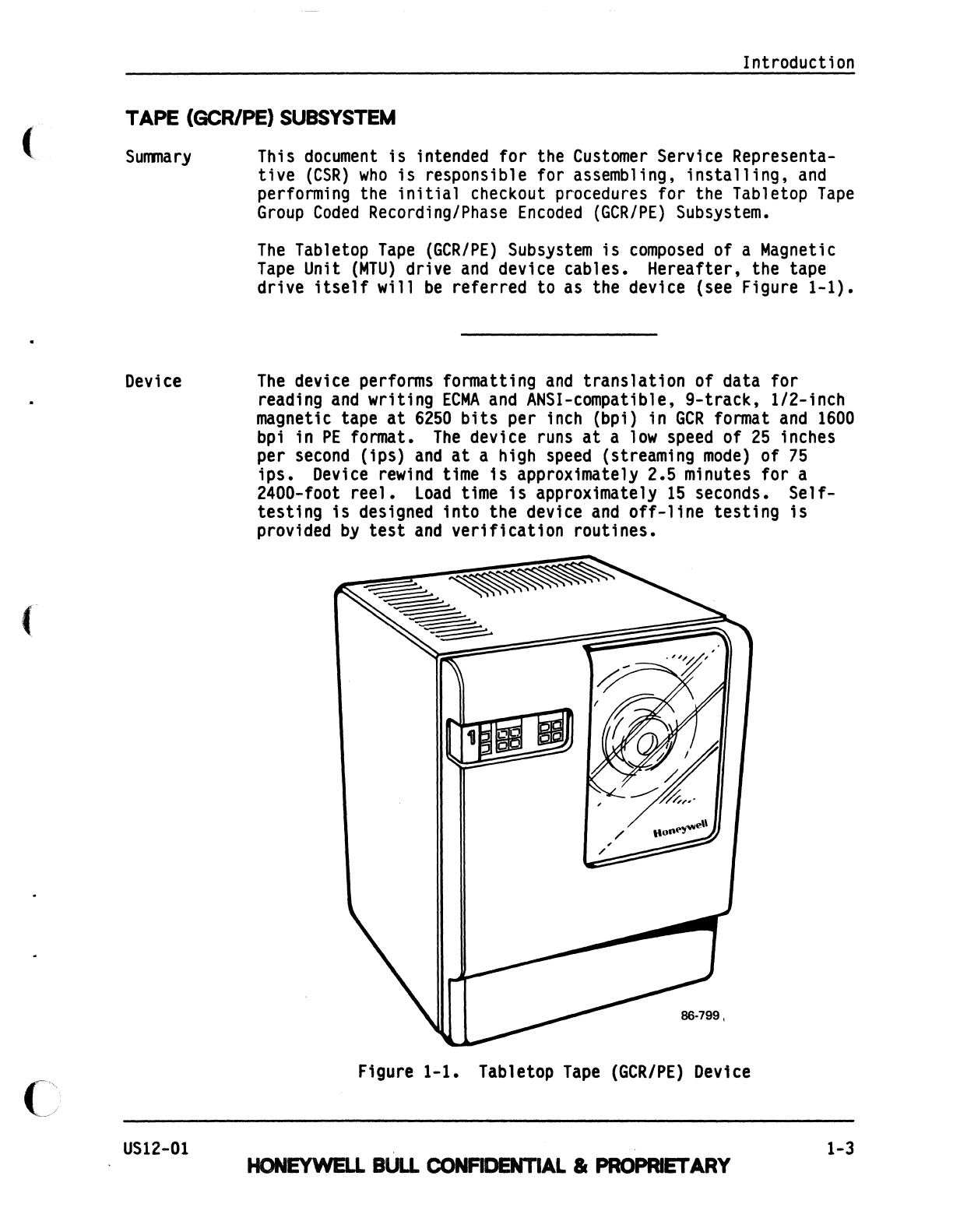
Tabletop
Tape
(GCR/PE)
Device.................................
1-3
1-2
Cabinet
Bulkhead
Device
Connectors............................
1-4
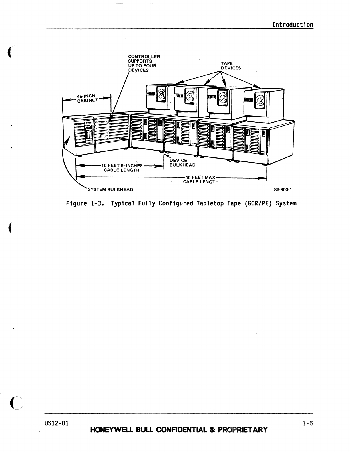
1-3
Typical
Fully
Configured
Tabletop
Tape
(GCR/PE)
System........
1-5
2-1
Position
Shipping
Cartons,
Open
System
Covers,
and
Remove
Panels.............................................
2-3
2-2 Installation Kit
Contents.....................................
2-5
2-3
Device
Preparation............................................
2-7
2-4
Card
Cage
Assembly............................................
2-11
2-5
Interface
Board
Switch
Locations
and
Settings.................
2-11
2-6 Install
Cable
Bulkhead
and
Internal
Bulkhead
Cables...........
2-13
2-7
Install Front
Door
and
Cover
Assemblies.......................
2-15
2-8
Device
Cabling................................................
2-17
2-9 Reinstall Panels
and
Close
Covers.............................
2-18
3-1
Tabletop
Tape
(GCR/PE)
Subsystem
Shipping
Cartons.............
3-3
3-2 Cabinet
Accessibility.........................................
3-5
3-3
Unpacking
the
Device..........................................
3-7
3-4
Mounting
the
Holding
Bracket..................................
3-9
3-5
Mounting
the Lifting
Handles..................................
3-11
3-6
Locking
the
Device
Leveling
Pads..............................
3-11
3-7
Removing
the Existing
Motor
Cover.............................
3-15
3-8 Installing the I-Inch
Foam
Pad,
New
Motor
Cover,
and
Lower
Side
Panel
••••••••••••••••••••••••••••••••••••••••••••••••••••
3-9
Mounting
the
Fan
Plenum
Assembly
and
Right
Side
Panel
•••••••••
3-10
Card
Cage
Assembly
•••••••••••••••••••••••••••••••••.••••••••••
3-11
Interface
Board
Switch
Locations
and
Settings
•••••••••••••••••
3-12
Installing the
Cable
Bulkhead
Assembly,
AC
Power
Cord,
and
Internal
Bulkhead
Cables
••••••••••••••••••••••••••••••••••••••
3-13
Plugging
in
the
Bulkhead
Cables
•••••••••••••••••••••••••••••••
3-14
Installing the Front
Door
Assembly
••••••••••••••••••••••••••••
3-15
Mounting
a
Device
Cover
Assembly
and
Cable
Cover
••••••••••••••
3-16 Device
Bulkhead
•••••••••••••••••••••••••••••••••••••••••••••••
3-17
Device
Bulkhead
Cabling
•••••••••••••••••••••••••••••••••••••••
3-18
Cabling
for Additional
Devices
1n
a
Daisy
Chain
System
••••••••
3-19
Plugging
in
Device
AC
Power
•••••••••••••••••••••••••••••••••••
3-20
Control
Panel
•••••••••••••••••••••••••••••••••••••••••••••••••
3-21
Re1nstalling the
System
Cabinet
Covers
and
Panels
•••••••••••••
1v
HONEYWB.L
BULL
CONFIDENTIAL
IcPROPRlET
ARY
3-15
3-17
3-19
3-19
3-21
3-21
3-23
3-25
3-27
3-29
3-31
3-33
3-35
3-37
US12-01