PS1202C, PS2402C REPLACEMENT POWER SUPPLY KITS FOR ELECTRONIC AIR CLEANERS
69-1137EF—05 2
INSTALLATION
When Installing this Product…
1. Read these instructions carefully. Failure to fol-
low them could damage the product or cause a
hazardous condition such as electrical shock.
2. Check the ratings given in the instructions and
on the product to make sure the product is suit-
able for your application.
3. Installer must be a trained, experienced service
technician.
4. After installation is complete, check out product
operation as provided in these instructions.
Electric Shock Hazard.
Safety Hazard.
Can cause electrical shock or equipment
damage.
Disconnect power before removing old power
supply board and installing replacement power
supply board. When servicing the F57 or F90,
stand on a stable work platform or ladder.
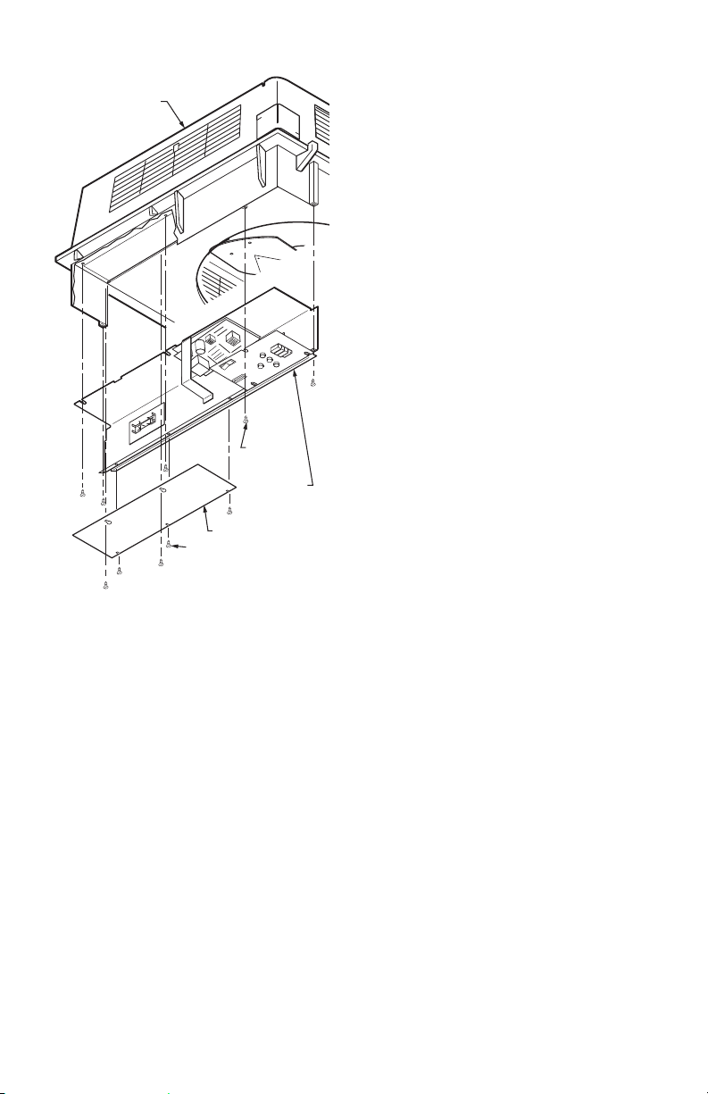
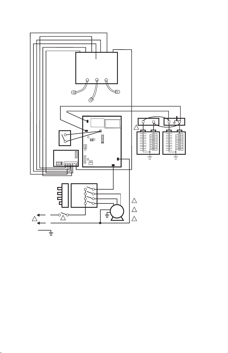
Fig. 1. Power supply location on F50E Two-Cell Air
Cleaners.
To Remove Old Power Supply
Board And Performance
Indicator Board
NOTE: It is advisable to observe the location of lead-
wires on the power supply to be replaced. Tag-
ging the lead-wires as they are removed will
help to correctly reconnect them.
Open access door or grille. See Fig. 1 through 5.
Open power box.
Remove W8600E terminal block and wiring. Save
screws for future use.
On the F90, remove the power supply assembly as
follows:
— Open the cover by pulling the two latches
located on the front of the cover and swinging
the cover down until it hangs (see Fig. 5).
— Remove the two prefilters and the two cells
from the channel guides.
— Loosen the screws holding the power supply
assembly cover plate and remove the cover
plate. See Fig. 6.
— Loosen the two screws on the inner wall of the
power supply assembly and three screws on
the top of the assembly. Slide the power supply
assembly toward the center of the air cleaner
and disconnect the two Molex connectors and
the one quick connect connector. See Fig. 6.
— Remove the power supply assembly to a table
or work bench to replace the power supply.
Disconnect the red ionizer and black collector leads
at the board quick connects.
Disconnect remaining input leads at the quick
connects.
Remove and set aside the sheet metal screws
holding the power supply board in place. Remove
the performance indicator board by clipping the
four plastic standoffs with diagonal cutters, or
squeezing the ends of the standoffs to release the
board. Remove and discard the board.