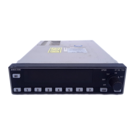
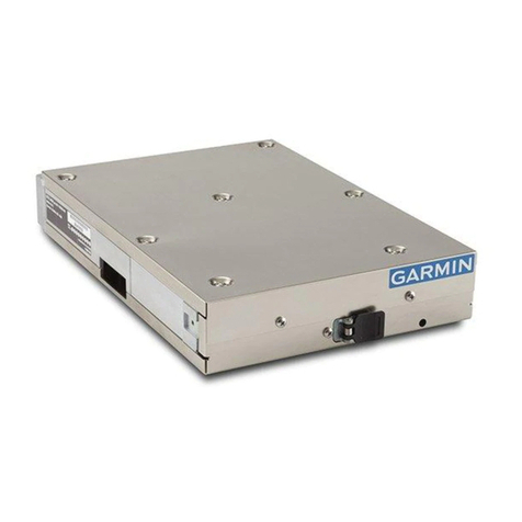
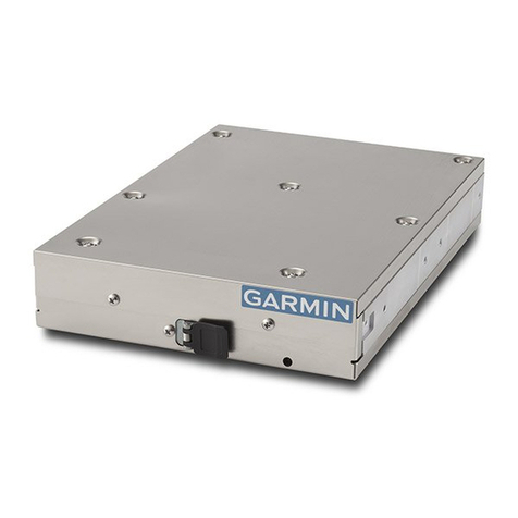
Honeywell KXP2290 Manual


HONEYWELL CONFIDENTIAL
This copyrighted work and all information are the property of Honeywell International Inc., contain trade
secrets and may not, in whole or in part, be used, duplicated, or disclosed for any purpose without prior
written permission of Honeywell International Inc. All Rights Reserved. Copyright 2005 Honeywell
International Inc.
REVISION HISTORY
Revision PRN/CO Description Date
- 768843 Initial Release See Cover Page
Honeywell International Inc. 001-05117-0010
KXP2290 Diversity Mode S Transponder Revision -
Alignment Procedure 2 of 11

HONEYWELL CONFIDENTIAL
Reference Documents:
The following documents apply to the KXP2290 Diversity Mode S Transponder.
1. Minimum Performance Specification (MPS),
KXP2290 004-02279-4000.
2. Product Structure Diagram, KXP2290 000-02000-0000.
3. KXP2290 Software Design Document, 721-00894-XXXX.
4. RTCA DO-181C Minimum Operational Performance Standards for
the Air Traffic Control Radar Beacon System/Mode Select
Airborne Equipment.
5. System Requirements Document, KXP2290 701-00731-XXXX.
Measurement Reference and Required Equipment List:
Measurement Reference:
Throughout this document, unless otherwise noted, receiver and transmitter power levels are
measured at the antenna end of a nominal 2dB loss coaxial cable.
1. KXP2290 Manual Test Panel: KPN 071-00224-0020
2. IFR ATC-1400A, (S-1403DL with MLD) or-1403DL without MLD)
DME/Transponder test set.
3. Oscilloscope: Tektronix TDS 320, 350, 380, 3054B, 520, 540C
or equivalent.
4. Digital multi meter, 3 ½ digits: Fluke 8010A or equivalent.
5. Power Supply, 0 to 30 Volts, 5 Amps or equivalent.
6. PC pentium_90, or better (Windows 95/98/ME/2000/ XP is not
acceptable).
7. KXP2290 Diagnostic Utility CD-ROM: KPN 222-30128-XXXX.
8. Coaxial Directional Coupler with a 30dB port.
9. 10dB Pad attenuator.
10. 20dB Pad attenuator.
11. 50 Ohm Load, BNC.
12. Spectrum Analyzer: HP 8951E or Equivalent
Honeywell International Inc. 001-05117-0010
KXP2290 Diversity Mode S Transponder Revision -
Alignment Procedure 3 of 11

HONEYWELL CONFIDENTIAL
Test Set Up
For
KXP2290 Transmitter Alignment
IFR S-1403DL
KeyPad
Display screen
PRF setting
RF power
port
RF Power
dipslay
Spectrum
Analyzer
Scope
Coupler
30dB
20dB
50ohm load
IFR 1400A
KXP2290
Computer
Bench Test
Box
Power
Supply
XMTR
Figure 1
Notes:
1. The IFR TX detector (XMTR Output) is connected to a channel
of the scope with a 50 ohm load.
2. The RF power to spectrum analyzer should have a 20dB pad to
spectrum analyzer input port.
Honeywell International Inc. 001-05117-0010
KXP2290 Diversity Mode S Transponder Revision -
Alignment Procedure 4 of 11

HONEYWELL CONFIDENTIAL
Preliminary UUT Set UP:
The Following Steps Must Be Preformed Before Power Is Applied To UUT.
Transmitter Final Board: (200-10256-0030)
b. Adjust R1 fully counter clockwise (CCW)
c. Adjust C44, C45 and C27 to mid range.
Transmitter Driver Board: (200-10252-0030)
a. Adjust R3 fully counter clockwise (CCW)
Test Equipment Set Up: See Figure 1
Computer Set Up:
1. Install Diagnostic Software
( KPN 222-30128-XXXX )
Drag Kxp_Diag.exe file onto desktop. Double-click icon to activate
program.
Test Panel Set Up:
1. Connect a RS232 cable from COMM Port of the computer to the RS232
DIAG input on the Test Panel (KPN 071-00224-0020).
2. Connect Bench Test Cable (KPN 200-10336-0050 or 200-10336-0120)
from the Test Panel to the KXP2290 (UUT).
3. Set Test Panel switches in the following positions:
a. Air/Gnd = “OFF”
b. Standby = “OUT”
c. UUT Strap = “XPDR #1”
d. Aircraft Power = “OFF”
4. Connect a +28 volt power supply to Test Panel, be sure the polarity is
correct.
Honeywell International Inc. 001-05117-0010
KXP2290 Diversity Mode S Transponder Revision -
Alignment Procedure 5 of 11

HONEYWELL CONFIDENTIAL
Test Equipment Set Up:
IFR ATC-1400A, S-1403DL Set UP:
1. S-1403DL set up:
a. Set IFR to OCTAL Mode:
1. Set menu to “C76”.
2. Move cursor to “:HEX”
3. Press “ON/CAL” key & toggle to OCTAL.
b. Set up for ATCRBS:
1. Set menu to “C10 f01”:ATC (ATCRBS)
c. Set up for Long Mode S:
1. Set menu to “C10 f02”:SEQ (Mode S).
2. Press the S menu key on the keypad.
3. Select: S000: D; UF05, PC=0, RR=20, DI=0, SD=100000,
ADDR=52525252 on the screen.
2. S-1400A set up:
a. Set the PRF to 100
b. Set XPDR Mode switch to “A”
c. Set SLS/ECHO to “-9dBm”
d. Set SLS/ECHO switch to “OFF”
e. Set the RF signal level to -50dBm
Scope:
1. Select channel 2 for observing the IFR detected Video Output (XMTR).
2. Select normal trigger on channel 2. Set the trigger position to 10%.
3. Select the Measurement mode and set for Pulse Width, Rise time, and Fall
time measurements.
Spectrum Analyzer:
1. Set the center frequency to 1090MHz.
2. Set the Bandwidth to 3 MHz.
3. Set the Span to 1 GHz (normal operation).
4. Set the Sweep to 10 seconds
NOTE:
Prior to Alignment, perform a visual inspection of all the test equipment.
Verify all connections are made per the Alignment Setup diagrams.
Verify all cables and fixtures are in good repair and free of any defects.
Honeywell International Inc. 001-05117-0010
KXP2290 Diversity Mode S Transponder Revision -
Alignment Procedure 6 of 11

HONEYWELL CONFIDENTIAL
UUT Initial Set Up:
Use the Diagnostic Utility program to initialize the UUT to be Aligned.
1. Double-click on the Icon of the previously installed Diagnostic Utility
program.
2. Set +28 volt Power Supply to “ON” position.
3. Set Test Panel Aircraft Power switch to “ON” position.
4. Be sure the correct revision of Boot, Application and Firmware are
loaded. The Diagnostic Utility program will display this information.
5. Set MODE S ADDRESS to “52525252” (Octal) or
“AAAAAA” (Hex)
6. Set 4096 CODE to “7777”
7. Set MAX AIR SPEED to “75-150”
8. Set OPERATIONAL MODE to “Altitude”
9. Set AIRBORN/GROUND to “Airborne”
10. Set DIVERSITY to “Enable”
11. CYCLE AIRCRAFT POWER
12. Set SQUITTER to “Disable”
Honeywell International Inc. 001-05117-0010
KXP2290 Diversity Mode S Transponder Revision -
Alignment Procedure 7 of 11

HONEYWELL CONFIDENTIAL
TX Driver and TX Final Alignment Procedures:
1. Set the IFR to ATCRBS.
2. Verify that R1 on the TX Final board and R3 on the TX Driver board are set fully CCW. Apply
unit power.
3. On the TX Driver board, measure the voltage at L4 (scope or voltmeter). Set this voltage to 4.5V
by adjusting R3 CW. Note that the total unit current draw at this time should be no more than
190ma.
4. On the TX Final board, attach scope probe to the junction of L11 and R16. Adjust R1 CW while
observing a positive pulse on the scope. Set this pulse height to 3.8 V (maximum is 4 V).
5. Adjust the scope to observe the 1st TX pulse. While observing this 1st pulse, on the TX Final
board, start by adjusting C27 first, then C44 and then C26 (in this order) for maximum TX
pulse power as observed on the scope and IFR Power Monitor. Also, observe this pulse and
adjust the three tuning caps slightly for the best Pulse Top flatness and Rise and Fall time
linearity.
6. Check the pulse Width measurement. It should be approximately 430nsec at this time. If not,
on the TX Driver board, adjust R4 (first) and then R30 to set the preliminary pulse width to
430ns. The pulse Rise time should be greater than 50ns and less than 100ns. The pulse Fall
time should be greater than 50ns and less than 170ns. Make minor readjustments to C27, C44,
and C26 on the TX Final board as necessary to bring the pulse Rise and Fall times within
specifications. Check the power output on the IFR display. It should be greater than 125W
minimum.
7. Set the scope delay to approximately 20.5usec and adjust as necessary to observe the last pulse
of the TX pulse train. Check the TX Pulse Width. It should be approximately 430nsec. If not,
make a slight adjustment to R4 then R30 on the driver board. Verify the pulse Rise and Fall
times are within the specifications listed above. If not, make minor adjustments to the TX
board tuning caps as necessary.
8. Set the IFR to Long Mode S.
9. Set up the scope to observe the first TX Pulse.
10. Check the pulse width measurement. It should be a minimum of 520 +/- 10nsec. If necessary,
on the TX Driver board, adjust R4 then R30 to set this pulse width to 520nsec. The pulse Rise
time should be greater than 50ns and less than 100ns. The pulse Fall time should be greater
than 50ns and less than 170ns. Again, if necessary, make minor readjustments to C27, C44,
and C26 on the TX Final board to bring the pulse Rise and Fall times within specifications.
Check the power output on the IFR display. It should be greater than 125W minimum.
Honeywell International Inc. 001-05117-0010
KXP2290 Diversity Mode S Transponder Revision -
Alignment Procedure 8 of 11
HONEYWELL CONFIDENTIAL
11. Set the scope delay to approximately 119.5usec and adjust as necessary to observe the last
pulse of the TX pulse train. Check the pulse Width. It should be 520nsec +/- 10nsec.
Make minor adjustments to R4 then R30 if necessary. Verify that the pulse Rise and Fall
times are within the specifications listed above. If not, make minor adjustments to the TX
board tuning caps as necessary.
12. Check the TX Pulse Spectrum on the spectrum analyzer. With a Span of 1GHz, verify there
are no spurs on either side of the 1090Mhz TX pulse.
13. Measure the close-in TX Pulse Spectrum with the analyzer Span set to 50MHz and the RES
BW set to 300Khz. The spectrum observed should meet the TX Pulse Spectrum requirements
shown below on both the lower and upper side frequencies down from the 1090Mhz peak:
MHz difference from 1090mHz dB down from 1090Mhz peak
>1.3 to <7 Mhz 3dB or more
>7 to <23 Mhz 20dB or more
Increase span to 200Mhz. Set RES BW to 3Mhz.
>23 to <78 Mhz 40dB or more
Increase span to 500Mhz.
>78Mhz 60dB or more
14. Make slight adjustments if necessary to C26, C27, and C44 on the TX Final board to bring the
side lobes within specifications.
15. Set the IFR back to ATCRBS.
16. Set the Spectrum analyzer Span to 1Ghz and the RES BW back to 3Mhz.
17. Repeat all TX Pulse Spectrum tests as listed above on both sides of the 1090Mhz peak. Verify
the spectrum measurements are within specifications. Make minor TX tuning
adjustments only if necessary. Note: When testing spectrums >78Mhz in ATCRBS
reduce the RES BW to 1Mhz.
18. Repeat the pulse Width measurements on the first and last TX pulse. The pulse Width should
now be 450 +/- 100 ns. If not, make minor adjustments to R4 and R30 on the Driver board.
Check the pulse Rise and Fall times for the first and last TX pulse. Verify they are within
specifications (Ref step 6). Make only miner adjustments as necessary.
Honeywell International Inc. 001-05117-0010
KXP2290 Diversity Mode S Transponder Revision -
Alignment Procedure 9 of 11

HONEYWELL CONFIDENTIAL
Test Set Up
For
KXP2290 Receiver Alignment
IFR S-1403DL
PRF setting
RF Port B
IFR 1400A
KXP2290
Computer
Bench Test
Box
POWER
SUPPLY
RF Port A
Key Pad
Display
Screen
Figure 2
Honeywell International Inc. 001-05117-0010
KXP2290 Diversity Mode S Transponder Revision -
Alignment Procedure 10 of 11

HONEYWELL CONFIDENTIAL
Unit Receiver Sensitivity Alignment:
See Figure 2 For Test Equipment Set UP:
1. Set IFR to ATCRBS, and set the PRF to 450.
2. On the KXP2290 Main Board set R1200 to its center position.
3. Connect a 2dB loss RF cable from IFR antenna port (A) to the KXP2290 Bottom
Antenna port (J2). The KXP2290 Top Antenna port (J3) is not connected to IFR
at this time.
4. Set IFR RF Level to -75dBm.
5. While observing the IFR for ATCRBS reply, adjust R2212 on the KXP2290
Receiver Board, to obtain a 50% to 70% reply.
6. Set IFR RF Level to -74dBm.
7. Observe the IFR for a 99% to 100% ATCRBS reply.
8. Connect a 2dB loss RF cable from IFR antenna port (A) to the KXP2290 Top
Antenna port (J3). The KXP2290 Bottom Antenna port (J2) is not connected to
IFR at this time.
9. Set IFR RF level to -75dBm.
10. While observing the IFR for ATCRBS reply, adjust R2211 on the KXP2290
Receiver Board, to obtain a 50% to 70% reply.
11. Set IFR RF level to -74dBm.
12. Observe the IFR for a 99% to 100% ATCRBS reply.
Honeywell International Inc. 001-05117-0010
KXP2290 Diversity Mode S Transponder Revision -
Alignment Procedure 11 of 11
Other manuals for KXP2290
1
Table of contents
Other Honeywell Marine Radio manuals

Honeywell
Honeywell KT 74 User manual

Honeywell
Honeywell ESSER IQ8 User manual

Honeywell
Honeywell BendixKing KT 76C User manual

Honeywell
Honeywell Esser RZT 8000 User manual

Honeywell
Honeywell KT73 User manual

Honeywell
Honeywell KXP2290 User manual

Honeywell
Honeywell KT 74 Manual

Honeywell
Honeywell ESSER IQ8FCT User manual
Popular Marine Radio manuals by other brands

Uniden
Uniden ATLANTIS 200 Guide d'utilisation

West Marine
West Marine VHF 150 owner's manual

Alpha Outback Energy
Alpha Outback Energy AlphaNet DM3 Series Installation & quick start guide

COBHAM
COBHAM SAILOR 6280 installation manual

uAvionix
uAvionix tailBeaconX TSO User and installation guide

ACSS
ACSS NXG-900 AML STC System maintenance manual