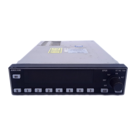
Honeywell KT 74 User manual

9201-B San Mateo Blvd N.E.
Albuquerque, New Mexico 87113
U.S.A.
CAGE: 6PC31
Telephone: 855-250-7027 (Toll-Free U.S.A./Canada)
Telephone: 602-365-7027 (International Direct)
Web site: www.bendixking.com/support
Publication Number D201308000037, Revision 0
Page T-1
Initial 15 Nov 2013
© Honeywell International Inc. Do not copy without express permission of Honeywell.
Installation Manual
KT 74 Mode S/ADS-B Out Transponder
Part Number CAGE
89000007-000001 6PC31
Legal Notice
Export Control
This document contains technical data and is subject to U.S. export regulations. These commodities, technology, or
software were exported from the United States in accordance with the export administration regulations. Diversion
contrary to U.S. law is prohibited.
ECCN: 7E994.

INSTALLATION MANUAL
89000007
Page T-2
15 Nov 2013
© Honeywell International Inc. Do not copy without express permission of Honeywell.
Proprietary Information Honeywell – Confidential
THIS COPYRIGHTED WORK AND ALL INFORMATION ARE THE PROPERTY OF HONEYWELL
INTERNATIONAL INC., CONTAIN TRADE SECRETS AND MAY NOT, IN WHOLE OR IN PART, BE USED,
DUPLICATED, OR DISCLOSED FOR ANY PURPOSE WITHOUT PRIOR WRITTEN PERMISSION OF
HONEYWELL INTERNATIONAL INC. ALL RIGHTS RESERVED.
Honeywell Materials License Agreement
The documents and information contained herein (“the Materials”) are the proprietary data of Honeywell
International Inc. and Honeywell Intellectual Properties Inc (collectively “Honeywell”). These Materials are provided
for the exclusive use of Honeywell Service Centers; Honeywell-authorized repair facilities; operators of Honeywell
aerospace products subject to an applicable product support agreement, their wholly owned-subsidiaries or a
formally designated third party service provider; and direct recipients of Materials from Honeywell’s Aerospace
Technical Publication Distribution. The terms and conditions of this License Agreement govern your use of these
Materials, except to the extent that any terms and conditions of another applicable agreement with Honeywell
regarding the operation, maintenance, or repair of Honeywell aerospace products conflict with the terms and
conditions of this License Agreement, in which case the terms and conditions of the other agreement will govern.
However, this License Agreement will govern in the event of a conflict between its terms and conditions and those
of a purchase order or acknowledgement.
1. License Grant - If you are a party to an applicable product support agreement, a Honeywell Service Center
agreement, or an authorized repair facility agreement, Honeywell hereby grants you a limited, non-exclusive
license to use these Materials to operate, maintain, or repair Honeywell aerospace products only in accordance
with that agreement.
If you are a direct recipient of these Materials from Honeywell’s Aerospace Technical Publication Distribution and
are not a party to an agreement related to the operation, maintenance or repair of Honeywell aerospace products,
Honeywell hereby grants you a limited, non-exclusive license to use these Materials to maintain or repair the
subject Honeywell aerospace products only at the facility to which these Materials have been shipped ("the
Licensed Facility"). Transfer of the Materials to another facility owned by you is permitted only if the original
Licensed Facility retains no copies of the Materials and you provide prior written notice to Honeywell.
2. Rights In Materials - Honeywell retains all rights in these Materials and in any copies thereof that are not
expressly granted to you, including all rights in patents, copyrights, trademarks, and trade secrets. No license to
use any Honeywell trademarks or patents is granted under this License Agreement.
3. Confidentiality - You acknowledge that these Materials contain information that is confidential and proprietary to
Honeywell. You agree to take all reasonable efforts to maintain the confidentiality of these Materials.
4. Assignment And Transfer - This License Agreement may be assigned to a formally designated service designee
or transferred to a subsequent owner or operator of an aircraft containing the subject Honeywell aerospace
products. However, the recipient of any such assignment or transfer must assume all of your obligations under this
License Agreement. No assignment or transfer shall relieve any party of any obligation that such party then has
hereunder.
5. Copies of Materials - Unless you have the express written permission of Honeywell, you may not make or permit
making of copies of the Materials. Notwithstanding the foregoing, you may make copies of only portions of the
Material for your internal use. You agree to return the Materials and any copies thereof to Honeywell upon the
request of Honeywell.
6. Term - This License Agreement is effective until terminated as set forth herein. This License Agreement will
terminate immediately, without notice from Honeywell, if you fail to comply with any provision of this License
Agreement or will terminate simultaneously with the termination or expiration of your applicable product support
agreement, authorized repair facility agreement, or your formal designation as a third party service provider. Upon
termination of this License Agreement, you will return these Materials to Honeywell without retaining any copies
and will have one of your authorized officers certify that all Materials have been returned with no copies retained.
INSTALLATION MANUAL
89000007
Page T-3
15 Nov 2013
© Honeywell International Inc. Do not copy without express permission of Honeywell.
7. Remedies - Honeywell reserves the right to pursue all available remedies and damages resulting from a breach
of this License Agreement.
8. Limitation of Liability - Honeywell does not make any representation regarding the use or sufficiency of the
Materials. THERE ARE NO OTHER WARRANTIES, WHETHER WRITTEN OR ORAL, EXPRESS, IMPLIED OR
STATUTORY, INCLUDING, BUT NOT LIMITED TO, (i) WARRANTIES ARISING FROM COURSE OF
PERFORMANCE, DEALING, USAGE, OR TRADE, WHICH ARE HEREBY EXPRESSLY DISCLAIMED, OR (ii)
WARRANTIES AGAINST INFRINGEMENT OF INTELLECTUAL PROPERTY RIGHTS OF THIRD PARTIES,
EVEN IF HONEYWELL HAS BEEN ADVISED OF ANY SUCH INFRINGEMENT. IN NO EVENT WILL
HONEYWELL BE LIABLE FOR ANY INCIDENTAL DAMAGES, CONSEQUENTIAL DAMAGES, SPECIAL
DAMAGES, INDIRECT DAMAGES, LOSS OF PROFITS, LOSS OF REVENUES, OR LOSS OF USE, EVEN IF
INFORMED OF THE POSSIBILITY OF SUCH DAMAGES. TO THE EXTENT PERMITTED BY APPLICABLE
LAW, THESE LIMITATIONS AND EXCLUSIONS WILL APPLY REGARDLESS OF WHETHER LIABILITY ARISES
FROM BREACH OF CONTRACT, WARRANTY, TORT (INCLUDING BUT NOT LIMITED TO NEGLIGENCE), BY
OPERATION OF LAW, OR OTHERWISE.
9. Controlling Law - This License shall be governed and construed in accordance with the laws of the State of New
York without regard to the conflicts of laws provisions thereof. This license sets forth the entire agreement between
you and Honeywell and may only be modified by a writing duly executed by the duly authorized representatives of
the parties.
Safety Advisory
WARNING: BEFORE THE MATERIALS CALLED OUT IN THIS PUBLICATION ARE USED, KNOW THE
HANDLING, STORAGE AND DISPOSAL PRECAUTIONS RECOMMENDED BY THE MANUFACTURER OR
SUPPLIER. FAILURE TO OBEY THE MANUFACTURERS’ OR SUPPLIERS’ RECOMMENDATIONS CAN
RESULT IN PERSONAL INJURY OR DISEASE.
This publication describes physical and chemical processes which can make it necessary to use chemicals,
solvents, paints, and other commercially available materials. The user of this publication must get the Material
Safety Data Sheets (OSHA Form 174 or equivalent) from the manufacturers or suppliers of the materials to be
used. The user must know the manufacturer/ supplier data and obey the procedures, recommendations, warnings
and cautions set forth for the safe use, handling, storage, and disposal of the materials.
Warranty/Liability Advisory
WARNING: HONEYWELL ASSUMES NO RESPONSIBILITY FOR ANY HONEYWELL EQUIPMENT WHICH IS
NOT MAINTAINED AND/OR REPAIRED IN ACCORDANCE WITH HONEYWELL’S PUBLISHED
INSTRUCTIONS AND/OR HONEYWELL’S FAA/SFAR 36 REPAIR AUTHORIZATION. NEITHER DOES
HONEYWELL ASSUME RESPONSIBILITY FOR SPECIAL TOOLS AND TEST EQUIPMENT FABRICATED BY
COMPANIES OTHER THAN HONEYWELL.
WARNING: INCORRECTLY REPAIRED COMPONENTS CAN AFFECT AIRWORTHINESS OR DECREASE THE
LIFE OF THE COMPONENTS. INCORRECTLY FABRICATED SPECIAL TOOLING OR TEST EQUIPMENT CAN
RESULT IN DAMAGE TO THE PRODUCT COMPONENTS OR GIVE UNSATISFACTORY RESULTS.
Copyright - Notice
Copyright 2013 Honeywell International Inc. All rights reserved.
Honeywell is a registered trademark of Honeywell International Inc.
All other marks are owned by their respective companies.

INSTALLATION MANUAL
89000007
Page T-4
15 Nov 2013
© Honeywell International Inc. Do not copy without express permission of Honeywell.
Blank Page

INSTALLATION MANUAL
89000007
Page TI-1
15 Nov 2013
© Honeywell International Inc. Do not copy without express permission of Honeywell.
TRANSMITTAL INFORMATION
THIS IS AN INITIAL RELEASE OF KT 74 MODE S/ADS-B OUT TRANSPONDER IM PUB. NO.
D201308000037 AND IS ISSUED FOR USE IN SUPPORT OF THE FOLLOWING:
Table TI-1 shows the applicable components.
Table TI-1.Applicable Components
Component Part Number Nomenclature
89000007-000001 KT 74 Mode S/ADS-B Out Transponder
Revision History
Table TI-2 shows the revision history of this IM.
Table TI-2.Revision History
Revision Number Revision Date
0 15 Nov 2013

INSTALLATION MANUAL
89000007
Page TI-2
15 Nov 2013
© Honeywell International Inc. Do not copy without express permission of Honeywell.
Blank Page

INSTALLATION MANUAL
89000007
Page RR-1
15 Nov 2013
© Honeywell International Inc. Do not copy without express permission of Honeywell.
RECORD OF REVISIONS
For each revision, write the revision number, revision date, date put in the manual, and your
initials in the applicable column.
NOTE: Refer to the Revision History in the TRANSMITTAL INFORMATION section for
revision data.
Revision
Number Revision
Date Date Put in
Manual By
Revision
Number Revision
Date Date Put in
Manual By

INSTALLATION MANUAL
89000007
Page RR-2
15 Nov 2013
© Honeywell International Inc. Do not copy without express permission of Honeywell.
Blank Page

INSTALLATION MANUAL
89000007
Page RTR-1
15 Nov 2013
© Honeywell International Inc. Do not copy without express permission of Honeywell.
RECORD OF TEMPORARY REVISIONS
Instructions on each page of a temporary revision tell you where to put the pages in your manual.
Remove the temporary revision pages only when discard instructions are given. For each
temporary revision, put the applicable data in the record columns on this page.
Definition of Status column: A TR may be active, incorporated, or deleted. “Active” is entered by
the holder of the manual. “Incorporated” means a TR has been incorporated into the manual and
includes the revision number of the manual when the TR was incorporated. “Deleted” means a TR
has been replaced by another TR, a TR number will not be issued, or a TR has been deleted.
Temporary
Revision
Number Status
Page
Number Issue
Date
Date
Put
in
Manual By
Date
Removed
from
Manual By

INSTALLATION MANUAL
89000007
Page RTR-2
15 Nov 2013
© Honeywell International Inc. Do not copy without express permission of Honeywell.
Blank Page

INSTALLATION MANUAL
89000007
* indicates pages changed or added data
F indicates a right foldout
LF indicates a left foldout
Page LEP-1
15 Nov 2013
© Honeywell International Inc. Do not copy without express permission of Honeywell.
LIST OF EFFECTIVE PAGES
Subject Page
Date
Title
T-1 15 Nov 2013
T-2 15 Nov 2013
T-3 15 Nov 2013
T-4 15 Nov 2013
Transmittal
Information
TI-1 15 Nov 2013
TI-2 15 Nov 2013
Record of
Revisions
RR-1 15 Nov 2013
RR-2 15 Nov 2013
Record of
Temporary
Revisions
RTR-1 15 Nov 2013
RTR-2 15 Nov 2013
List of Effective
Pages
LEP-1 15 Nov 2013
LEP-2 15 Nov 2013
Table of
Contents
TC-1 15 Nov 2013
TC-2 15 Nov 2013
TC-3 15 Nov 2013
TC-4 15 Nov 2013
TC-5 15 Nov 2013
TC-6 15 Nov 2013
Introduction
INTRO-1 15 Nov 2013
INTRO-2 15 Nov 2013
Subject Page
Date
INTRO-3 15 Nov 2013
INTRO-4 15 Nov 2013
INTRO-5 15 Nov 2013
INTRO-6 15 Nov 2013
Section 1
General
Information
1-1 15 Nov 2013
1-2 15 Nov 2013
1-3 15 Nov 2013
1-4 15 Nov 2013
1-5 15 Nov 2013
1-6 15 Nov 2013
1-7 15 Nov 2013
1-8 15 Nov 2013
1-9 15 Nov 2013
1-10 15 Nov 2013
1-11 15 Nov 2013
1-12 15 Nov 2013
1-13 15 Nov 2013
1-14 15 Nov 2013
Section 2
Installation
2-1 15 Nov 2013
2-2 15 Nov 2013
F 2-3/2-4 15 Nov 2013
2-5 15 Nov 2013
2-6 15 Nov 2013
2-7 15 Nov 2013
2-8 15 Nov 2013
2-9 15 Nov 2013
2-10 15 Nov 2013

INSTALLATION MANUAL
89000007
* indicates pages changed or added data
F indicates a right foldout
LF indicates a left foldout
Page LEP-2
15 Nov 2013
© Honeywell International Inc. Do not copy without express permission of Honeywell.
Subject Page
Date
2-11 15 Nov 2013
2-12 15 Nov 2013
2-13 15 Nov 2013
2-14 15 Nov 2013
2-15 15 Nov 2013
2-16 15 Nov 2013
2-17 15 Nov 2013
2-18 15 Nov 2013
2-19 15 Nov 2013
2-20 15 Nov 2013
Section 3
System
Interconnect
3-1 15 Nov 2013
3-2 15 Nov 2013
F 3-3/3-4 15 Nov 2013
Section 4
Post-Installation
Configuration,
Calibration, and
Checkout
4-1 15 Nov 2013
Subject Page
Date
4-2 15 Nov 2013
4-3 15 Nov 2013
4-4 15 Nov 2013
4-5 15 Nov 2013
4-6 15 Nov 2013
4-7 15 Nov 2013
4-8 15 Nov 2013
Section 5
Instructions for
Continued
Airworthiness
5-1 15 Nov 2013
5-2 15 Nov 2013
Appendix A
Enviromental
Qualification
A-1 15 Nov 2013
A-2 15 Nov 2013
A-3 15 Nov 2013
A-4 15 Nov 2013

INSTALLATION MANUAL
89000007
Page TC-1
15 Nov 2013
© Honeywell International Inc. Do not copy without express permission of Honeywell.
TABLE OF CONTENTS
Title Page
INTRODUCTION.................................................................................................................... INTRO-1
1. How To Use This Manual ...........................................................................................................INTRO-1
A. General..................................................................................................................................INTRO-1
B. Observance of Manual Instructions ......................................................................................INTRO-1
C. Symbols ................................................................................................................................INTRO-1
D. Units of Measure...................................................................................................................INTRO-2
E. Standard Practices Manual...................................................................................................INTRO-2
F. Electrostatic Discharge .........................................................................................................INTRO-2
2. BendixKing Technical Publications Support...............................................................................INTRO-2
A. Honeywell Aerospace Online Technical Publications Website.............................................INTRO-2
B. BendixKing Customer Support..............................................................................................INTRO-2
3. References .................................................................................................................................INTRO-2
A. Honeywell/Vendor Publications ............................................................................................INTRO-2
B. Other Publications.................................................................................................................INTRO-3
4. Acronyms and Abbreviations......................................................................................................INTRO-4
A. General..................................................................................................................................INTRO-4
5. Software History .........................................................................................................................INTRO-5
A. Software Data .......................................................................................................................INTRO-5
SECTION 1 GENERAL INFORMATION ........................................................................................ 1-1
1.1 KT 74 Description........................................................................................................................ 1-1
1.2 Interfaces.....................................................................................................................................1-1
1.3 Regulatory ...................................................................................................................................1-2
1.3.1 Approved Deviations ...................................................................................................................1-3
1.4 Physical Specifications (in Tray) .................................................................................................1-3
1.5 Installation Approval ....................................................................................................................1-4
1.6 TSO Failure Condition Classification ..........................................................................................1-4
1.7 Non – TSO Functions..................................................................................................................1-4
1.8 KT 74 Mode S Transponder Items ..............................................................................................1-4
1.9 Installation Kit ..............................................................................................................................1-5
1.10 Documentation Kit .......................................................................................................................1-5
1.11 Required Items ............................................................................................................................1-5
1.12 Normal Operations Overview ......................................................................................................1-6
1.13 Display.........................................................................................................................................1-6

INSTALLATION MANUAL
89000007
Page TC-2
15 Nov 2013
© Honeywell International Inc. Do not copy without express permission of Honeywell.
Title Page
1.14 Mode Selector Knob....................................................................................................................1-7
1.15 Push Buttons ...............................................................................................................................1-7
1.16 Squawk Code Entry.....................................................................................................................1-7
1.17 Flight Timer..................................................................................................................................1-8
1.18 Stopwatch....................................................................................................................................1-8
1.19 Flight ID Entry..............................................................................................................................1-8
1.20 Altitude Monitor............................................................................................................................1-8
1.21 ADS-B Monitor............................................................................................................................. 1-9
1.22 Warning Messages......................................................................................................................1-9
1.23 Fault Annunciation.......................................................................................................................1-9
1.24 Low Temperature Operation .......................................................................................................1-9
1.25 Limited Warranty .......................................................................................................................1-10
1.26 ADS-B Compliance ...................................................................................................................1-11
1.27 ADS-B Parameters Supported ..................................................................................................1-11
1.28 FAA 91.227 Compliance ...........................................................................................................1-13
1.29 AMC 20-24 Compliance ............................................................................................................1-13
1.30 Automatic Air/Ground Determination ........................................................................................1-13
SECTION 2 INSTALLATION.......................................................................................................... 2-1
2.1 Unpacking and Inspecting Equipment......................................................................................... 2-1
2.2 Mounting......................................................................................................................................2-1
2.3 Installation Drawings ...................................................................................................................2-1
2.4 Cooling Requirements.................................................................................................................2-5
2.5 Electrical Connections................................................................................................................. 2-5
2.5.1 Primary Interface – Pinout...........................................................................................................2-5
2.5.2 Secondary Interface – Pinout ......................................................................................................2-7
2.5.3 Orientation Diagram ....................................................................................................................2-8
2.6 Interface Details ..........................................................................................................................2-9
2.6.1 Power Input .................................................................................................................................2-9
2.6.2 Lighting Bus Input........................................................................................................................2-9
2.6.3 Mutual Suppression...................................................................................................................2-10
2.6.4 Altitude Inputs and Output.........................................................................................................2-10
2.6.5 Squat Switch Input ....................................................................................................................2-11
2.6.6 Ident Switch Input......................................................................................................................2-11
2.6.7 External Standby Input ..............................................................................................................2-11
2.6.8 Audio Output..............................................................................................................................2-11

INSTALLATION MANUAL
89000007
Page TC-3
15 Nov 2013
© Honeywell International Inc. Do not copy without express permission of Honeywell.
Title Page
2.6.9 Altitude Alerter Output ...............................................................................................................2-12
2.6.10 GPS Position Input ....................................................................................................................2-12
2.6.11 TIS-A Traffic Output ..................................................................................................................2-12
2.7 Molex Crimp Terminals .............................................................................................................2-13
2.8 Antenna Installation...................................................................................................................2-13
2.8.1 Antenna Cable...........................................................................................................................2-14
2.8.2 BNC Connector .........................................................................................................................2-15
2.9 Tray/BNC Connector Assembly ................................................................................................2-18
SECTION 3 SYSTEM INTERCONNECT ....................................................................................... 3-1
3.1Basic Interconnect Diagram ........................................................................................................3-1
SECTION 4 POST-INSTALLATION CONFIGURATION, CALIBRATION, AND CHECKOUT ....... 4-1
4.1 Post Installation Checks ..............................................................................................................4-1
4.2 Installation Setup and Test.......................................................................................................... 4-1
4.3 Configuration Items .....................................................................................................................4-3
4.3.1 Aircraft Registration/VFR Flight ID ..............................................................................................4-3
4.3.2 Aircraft Address Programming ....................................................................................................4-3
4.3.3 VFR Squawk Code......................................................................................................................4-3
4.3.4 Airspeed Category.......................................................................................................................4-3
4.3.5 Aircraft Category .........................................................................................................................4-4
4.3.6 Squat Switch Source ...................................................................................................................4-4
4.3.7 ARINC TIS-A Output ...................................................................................................................4-4
4.3.8 Serial TIS-A Output .....................................................................................................................4-4
4.3.9 GPS Input ....................................................................................................................................4-4
4.3.10 GPS/TIS-A Line Speed ...............................................................................................................4-4
4.3.11 GPS System Certification Level ..................................................................................................4-5
4.3.12 GPS NACv................................................................................................................................... 4-5
4.3.13 Measurement Unit .......................................................................................................................4-5
4.3.14 Aircraft Length and Width............................................................................................................4-5
4.3.15 GPS Antenna Offset.................................................................................................................... 4-5
4.3.16 ADS-B Receiver Options.............................................................................................................4-6
4.3.17 Audio Volume ..............................................................................................................................4-6
4.3.18 LCD Dim Point.............................................................................................................................4-6
4.3.19 LCD Brightness Curve................................................................................................................. 4-6
4.4 Testitems ....................................................................................................................................4-6

INSTALLATION MANUAL
89000007
Page TC-4
15 Nov 2013
© Honeywell International Inc. Do not copy without express permission of Honeywell.
Title Page
4.4.1 Interface Check ...........................................................................................................................4-6
4.4.2 Altitude Check .............................................................................................................................4-7
4.4.3 Lighting Bus.................................................................................................................................4-7
4.4.4 Temperature................................................................................................................................4-7
4.4.5 GPS Interface ..............................................................................................................................4-7
4.5 Warnings and Faults ...................................................................................................................4-7
SECTION 5 INSTRUCTIONS FOR CONTINUED AIRWORTHINESS .......................................... 5-1
5.1 Continued Airworthiness .............................................................................................................5-1
5.2 Cleaning the KT 74 Transponder ................................................................................................5-1
APPENDIX A ENVIROMENTAL QUALIFICATION........................................................................A-1

INSTALLATION MANUAL
89000007
Page TC-5
15 Nov 2013
© Honeywell International Inc. Do not copy without express permission of Honeywell.
LIST OF FIGURES
Title Page
Figure INTRO-1. Symbols...................................................................................................... INTRO-1
Figure 1-1. KT 74 Display ............................................................................................................... 1-6
Figure 2-1. KT 74 Installation Drawing............................................................................................ 2-3
Figure 2-2. Primary Interface Pinout Locations............................................................................... 2-7
Figure 2-3. Secondary Interface Pinout Locations .......................................................................... 2-8
Figure 2-4. KT 74 Connector Positions ........................................................................................... 2-9
Figure 2-5. Molex Crimp Terminals............................................................................................... 2-13
Figure 2-6. Coax Cable Stripping Dimensions .............................................................................. 2-16
Figure 2-7. Coax Cable Inner and Outer Shield Orientation ......................................................... 2-16
Figure 2-8. Coax Cable Outer Shield to BNC Solder Location ..................................................... 2-17
Figure 2-9. Coax Cable and BNC Heat Shrink Location ............................................................... 2-17
Figure 2-10. BNC Completed Assembly ....................................................................................... 2-18
Figure 2-11. Tray / BNC Connector Assembly.............................................................................. 2-19
Figure 3-1. KT 74 Basic Interconnect Diagram ............................................................................... 3-3
Figure 4-1. KT 74 Transponder....................................................................................................... 4-2

INSTALLATION MANUAL
89000007
Page TC-6
15 Nov 2013
© Honeywell International Inc. Do not copy without express permission of Honeywell.
LIST OF TABLES
Title Page
Table 1-1. Interface Services .......................................................................................................... 1-1
Table 1-2. Regulatory Data ............................................................................................................. 1-2
Table 1-3. Physical Specifications .................................................................................................. 1-3
Table 1-4. Included Transponder Items .......................................................................................... 1-4
Table 1-5. Installation Kit................................................................................................................. 1-5
Table 1-6. Documentation Kit.......................................................................................................... 1-5
Table 1-7. Push Button Functions................................................................................................... 1-7
Table 1-8. ADS-B Parameters ...................................................................................................... 1-11
Table 2-1. Primary Interface Pinout Locations ................................................................................ 2-6
Table 2-2. Secondary Interface Pinout Locations ........................................................................... 2-7
Table 2-3. Maximum Usable Cable Lengths ................................................................................. 2-14
Table 4-1. Warning Messages ........................................................................................................ 4-7
Table 4-2. Fault Messages.............................................................................................................. 4-8
Table A-1. Environmental Qualification Form .................................................................................A-1

INSTALLATION MANUAL
89000007
Page INTRO-1
15 Nov 2013
© Honeywell International Inc. Do not copy without express permission of Honeywell.
INTRODUCTION
1. How To Use This Manual
A. General
(1) This publication gives maintenance instructions for the equipment shown on
the title page.
(2) Standard maintenance procedures that technicians must know are not given
in this manual.
(3) This publication is written in agreement with the ATA Specification.
(4) Warnings, cautions, and notes in this manual give the data that follows:
A WARNING gives a condition or tells personnel what part of an operation
or maintenance procedure, which if not obeyed, can cause injury or death
A CAUTION gives a condition or tells personnel what part of an operation
or maintenance procedure, which if not obeyed, can cause damage to the
equipment
Warnings and cautions go before the applicable paragraph or step. Notes
follow the applicable paragraph or step.
B. Observance of Manual Instructions
(1) Make sure that you carefully obey all safety, quality, operation, and shop
procedures for the unit.
(2) All personnel who operate equipment and do maintenance specified in this
manual must know and obey the safety precautions.
C. Symbols
(1) The symbols and special characters are in agreement with IEEE Publication
260 and IEC Publication 27. Special characters in text are spelled out.
(2) The signal mnemonics, unit control designators, and test designators are
shown in capital letters.
(3) The signal names followed by an “*” show an active low signal.
(4) The symbols in Figure INTRO 1 show ESDS and moisture sensitive devices.
Figure INTRO 1. Symbols

INSTALLATION MANUAL
89000007
Page INTRO-2
15 Nov 2013
© Honeywell International Inc. Do not copy without express permission of Honeywell.
D. Units of Measure
(1) Measurements, weights, temperatures, dimensions, and other values are
expressed in the USMS followed by the appropriate SI metric units in
parentheses. Some standard tools or parts such as drills, taps, bolts, nuts,
etc. do not have an equivalent.
E. Standard Practices Manual
(1) Standard cleaning, check, repair, and assembly procedures applicable to
multiple models can be found in a standard practices manual. Refer to
Paragraph 2.
F. Electrostatic Discharge
(1) Touch the items susceptible to electrostatic discharge in accordance with
MIL-HDBK-263. Refer to MIL-STD-1686 for definition of the standards and
conditions.
2. BendixKing Technical Publications Support
A. Honeywell Aerospace Online Technical Publications Website
(1) Go to the Honeywell Online Technical Publications Website at
(www.myaerospace.com).
To download or see publications online
To order a publication
To tell Honeywell of a possible data error in a publication.
B. BendixKing Customer Support
(1) Call BendixKing Customer Support for all Parts, Repair, Technical Support,
and Sales information. Contact BendixKing Customer Support at:
Telephone: 855-250-7027 (Toll Free U.S.A./Canada)
Telephone: 602-365-7027 (International)
Website: www.bendixking.com/support
Email: [email protected].
3. References
A. Honeywell/Vendor Publications
(1) Related Honeywell publications in this manual are shown in the list that
follows:
Pub. No. D201308000036, KT 74 Mode S Transponder Pilot’s Guide
ATA No. 20-00-03 (Pub. No. A09-1100-004), Standard Repair
Procedures for Honeywell Avionics Equipment Instruction Manual.
Other manuals for KT 74
1
This manual suits for next models
1
Table of contents
Other Honeywell Marine Radio manuals

Honeywell
Honeywell KT 74 Manual

Honeywell
Honeywell ESSER IQ8 User manual

Honeywell
Honeywell KXP2290 User manual

Honeywell
Honeywell KXP2290 Manual

Honeywell
Honeywell KT73 User manual

Honeywell
Honeywell BendixKing KT 76C User manual

Honeywell
Honeywell ESSER IQ8FCT User manual

Honeywell
Honeywell Esser RZT 8000 User manual