Hood Depot KAP Series User manual

Installation, Operation and Maintenance Manual
KAP Series -Air Purication Unit
Commercial Kitchen Ventilation Products

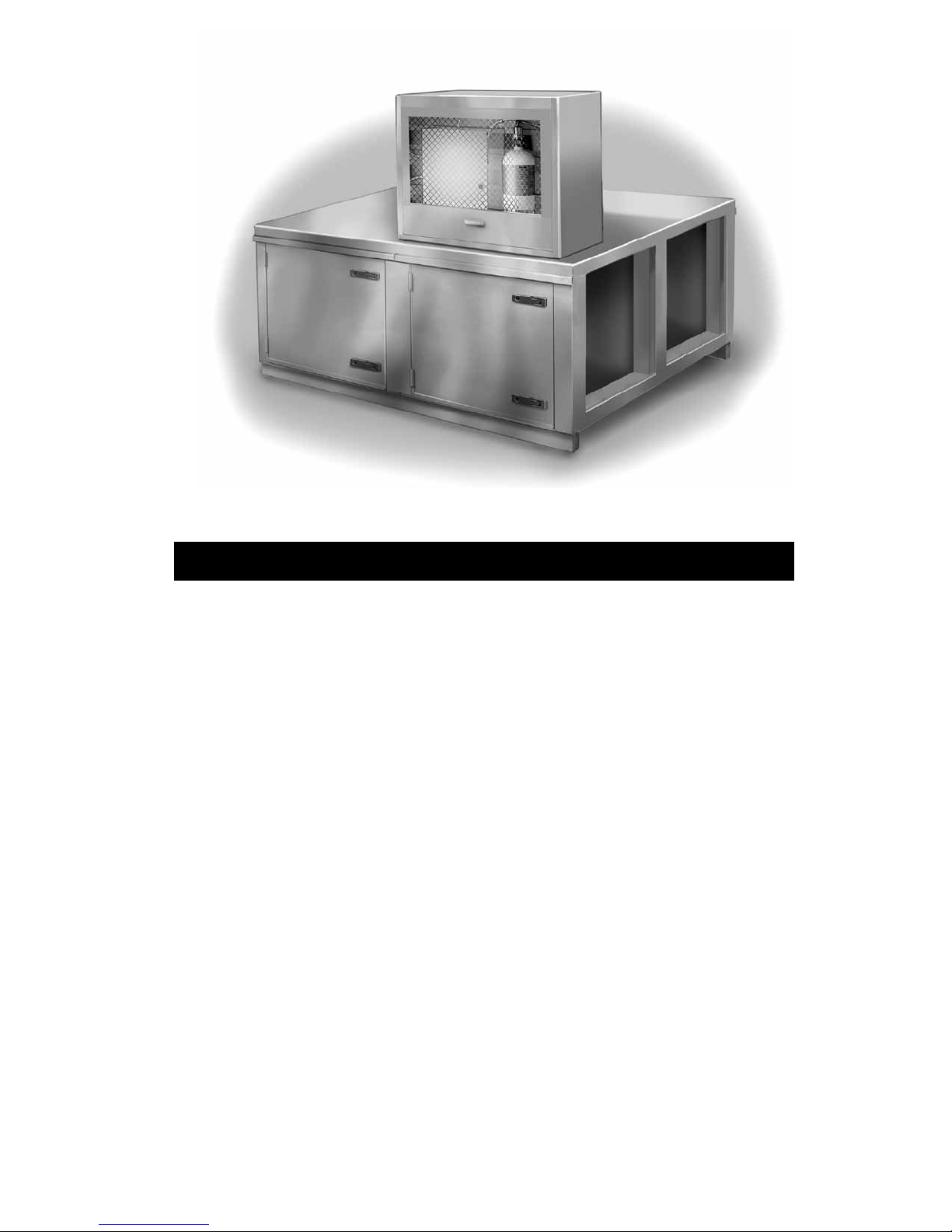
DESCRIPTION................................................................................................... 3
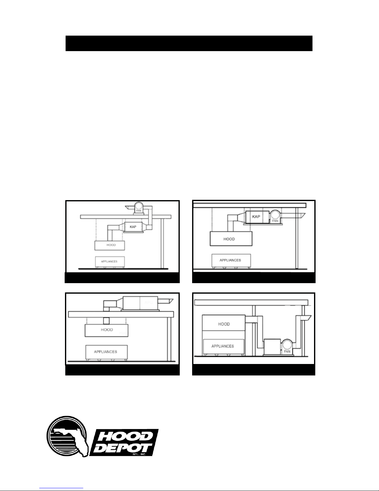
Common Installation Formats........................................................................ 4
INSTALLATION................................................................................................... 4
Preparation.................................................................................................... 4
Duct Work & Minimum Sizes......................................................................... 5
Grease/Water Drains..................................................................................... 6
Roof Installation / Floor Installation............................................................... 6
Ceiling Mount Installation.............................................................................. 7
Air Pressure Switch...................................................................................... 8
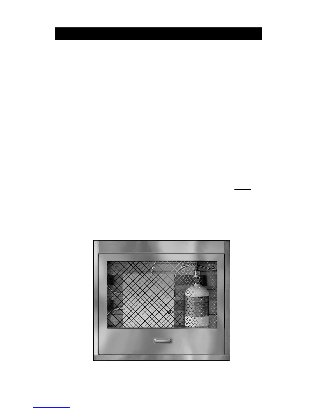
Fire System.................................................................................................... 9
OPERATION......................................................................................................10
Tools Required..............................................................................................10
Start-Up Check List.......................................................................................10
Start-Up Procedure.......................................................................................10
Troubleshooting.............................................................................................11
General Maintenance....................................................................................12
Filter Chart....................................................................................................13
Gasket Chart.................................................................................................13
Maintenance Intervals...................................................................................14
DOCUMENTATION........................................................................................... 15
Job & Site Information..................................................................................15
Name Plate/APU Information........................................................................15
Maintenance Record.................................................................................. 16
Listings..........................................................................................................17
Warranty........................................................................................................17
HD Service Dept...........................................................................................17
Commercial Kitchen Ventilation Products
710 S. Powerline Road, Deereld Beach, FL 33442 • 954 570-4083 • 800 322-8730 • www.hooddepot.net
CONTENTS

Commercial Kitchen Ventilation Products
710 S. Powerline Road, Deereld Beach, FL 33442 • 954 570-4083 • 800 322-8730 • www.hooddepot.net
DESCRIPTION
The listed air purication unit is suitable for the removal of smoke, grease laden
vapors and odors in commercial cooking installations. Hood Depot KAP purication
units are specied in CFM ratings from 5,000 to 40,000 CFM to handle all size kitch-
ens with any cooking equipment conguration. Grease ducts must still conform to
NFPA 96 and your local mechanical codes applicable to gauges, sizing and clean-
out requirements.
If a grease re has occurred, the system should be dismantled and inspected by a
professional engineer. Hood Depot International™ cannot be held responsible for
grease duct systems that are not properly maintained or have been subjected to a
grease re.
COMMON INSTALLATION FORMATS
Interior Split Fan & Filter Interior Horizontal Suspension
Exterior Roof Mounted
Pg. 3
Interior Floor Mounted
KAP
KAP

Commercial Kitchen Ventilation Products
710 S. Powerline Road, Deereld Beach, FL 33442 • 954 570-4083 • 800 322-8730 • www.hooddepot.net
INSTALLATION
Installation must be done in strict accordance with the designed airow, exhaust
fan placement, lters and construction details required by this manual. Lifting the
unit in place must be accomplished by using an equipment lift (rated above the unit
weight) or by hoisting using the proper hoisting straps (see below).
PREPARATION
1. Installation site should be clear to safely lift unit into proper position. Be sure
hoisting equipment and/or lifts are adequate to the weight load of the unit according
to manufacturer’s estimated weight.
2. Position unit to allow at least 34” of clearance on the access side of unit to open
door, replace lters and perform maintenance.
3. Unit should be located as close to the space it serves as practical to avoid lengthy
and complex duct runs. This will reduce total re hazard exposure and amount of
duct to be cleaned.
4. When the unit is ground or oor mounted, make sure it sits at least 6” (minimum)
off the ground for interior location and 18” (minimum) above ground for exterior loca-
tions including roof mounted.
5. The exhaust fan must be located between the air purication unit and the dis-
charge duct. DO NOT locate the fan between the hood and the air purication unit
as this would cause the KAP to be under positive pressure.
6. It is recommended that the unit’s grease drains are connected to the building
grease interceptor or an approved building drain system.
Pg. 4

Commercial Kitchen Ventilation Products
710 S. Powerline Road, Deereld Beach, FL 33442 • 954 570-4083 • 800 322-8730 • www.hooddepot.net
(INSTALLATION Cont’d.)
Performance of the air purication unit is highly affected by ductwork conguration,
proper alignment and seals. The following airow factors must be accounted for:
1. Any change in duct direction must be at least ve duct diameters away from the
unit inlet. The maximum velocity at the inlet of the unit must be less than 1,000 feet
per minute.
2. The air purication unit requires commercial (NFPA 96) or Listed grease duct-
work. Clearance ratings of any ductwork connected to the unit apply to the unit as
well and must be installed in accordance with IMC, NFPA 96 and state and local
codes.
3. All grease ducts before or after the KAP must be designed and installed as per
NFPA 96, local mechanical/building codes, SMACNA and any/all state and local
codes.
DUCTWORK
Each section of the unit contains a drain that should be connected to an approved
grease interceptor or to an approved drainage point to allow water to drain away
from the unit. If installed outdoors, the drains must be piped in such a way to avoid
water build-up in pipes that could burst in freezing conditions. It is recommended
that units located where freezing may occur have electric heat tape.
GREASE/WATER DRAINS
Drain line must be pitched for proper drainage
Pg. 5

(INSTALLATION Cont’d.)
When roof mounting, the KAP unit should be mounted on a roof-curb or rail at least
18” above the roof surface. Secure the unit on a support frame with at least eight (8)
#14 anchor bolts, welding 1” long every 12” or AHJ approved fasteners. Roof curb
rail to be mounted according to federal, state and local codes. Drain lines and roof
curb rails that penetrate the roof need to be properly ashed to avoid roof leaks. Be
sure to allow proper clearances for service access doors (see page 4).
ROOF INSTALLATION
When mounting the KAP unit on a oor, make sure it is mounted on support rails
with a minimum of 8” from the bottom of unit to the oor. Verify with your plumber
that this is sufcient clearance for the drains. Secure the unit through the unit sup-
port frame to the rail with at least eight (8) #14 sheet metal screws, anchor bolts or
AHJ approved fasteners. Secure support rails to the oor in accordance with fed-
eral, state and local codes. Make sure the unit has proper clearance for the service
access doors (see page 4). Make sure the bottom of the unit (not including support
frame) has at least 18” clearance from combustibles as per NFPA 96 and federal,
state and local codes.
INDOOR/FLOOR MOUNTED INSTALLATIONS
Pg. 6
710 S. Powerline Road, Deereld Beach, FL 33442 • 954 570-4083 • 800 322-8730 • www.hooddepot.net

When hanging the KAP from the ceiling/roof structure above, make sure it is mount-
ed with structural steel or uni-strut supports from underneath the unit. Verify the
size and number of supports required as well as ceiling integrity with your building’s
structural engineer. Make sure that the supports do not interfere with the service ac-
cess doors or with lter removal by providing proper clearance (see page 4). Make
sure the unit has 18” clearance from combustibles as per NFPA 96 and federal,
state and local codes.
INDOOR/CEILING MOUNTED INSTALLATIONS
INSTALLATION (Cont’d.)
Pg. 7
710 S. Powerline Road, Deereld Beach, FL 33442 • 954 570-4083 • 800 322-8730 • www.hooddepot.net

(INSTALLATION Cont’d.)
Air pressure switch is factory preset to .15” w.c. above the internal static pressure
of the unit (with clean lters). The pressure switch is located in downstream lter
module. Route wiring from hood control panel to the unit using 1/2” conduit through
quick-seal (lower right of lter module). Use existing conduit in the module to route
wires from module exterior to pressure switch (see wiring label above switch). Tight-
en all conduit ttings. When lters become clogged, the switch will close kitchen
illumination lighting to signal the cleaning or replacement of lters.
AIR PRESSURE SWITCH
Air Pressure Switch
(Within downstream air ow)
Pg. 8
Air Pressure Switch Location
Air Line Routing
710 S. Powerline Road, Deereld Beach, FL 33442 • 954 570-4083 • 800 322-8730 • www.hooddepot.net

(INSTALLATION Cont’d.)
Air Purication Units require a re suppression system to be installed with the unit.
The HD KAP Series unit can be factory tted with Kidde, Ansul or Buckeye re
equipment products. The system uses fusible links to activate the re system. The
KAP re system must be interlocked with a hood re suppression system so that it
may be activated by the hood system even in the absence of re in the KAP and is
activated by the KAP even in the absence of re in the hood.
If the re suppression system is accidently activated, the disposable lters and pre-
lter must be replaced. Immediately discard all lters and wash (with soap and wa-
ter) any part of the unit that was in contact with the re suppressant.
If a re occurs in the ductwork leading to the APU, the following maintenance must
be done:
1. The unit must be cleaned of all suppression agent and grease.
2. All lters must be replaced including the pre-lter.
3. Replace any damaged gasketing.
4. Fire-damaged components of the KAP, if any, must be replaced by
by factory service personnel.
FIRE SYSTEM
Installation, repair or retting of the re system must be done ONLY by a
licensed re system installer according to exact manufacturer guidelines.
A utility cabinet is recommended for indoor or outdoor installations to house the re
system. An optional heated temperature controller is available upon request.
FIRE SYSTEM UTILITY CABINET
Pg. 9
710 S. Powerline Road, Deereld Beach, FL 33442 • 954 570-4083 • 800 322-8730 • www.hooddepot.net

OPERATION
Before starting up the KAP, check all fasteners for tightness and be sure to check
the module connection seal and door seals. With power to the fan shut off, check
the airow direction of the lters to match the label on the lters.
START-UP TOOLS REQUIRED:
1. Standard Hand Tools
2. Static Pressure Meter
START-UP PROCEDURE:
1. Check duct connections to inlet and outlet of unit for proper welds.
2. Check that entire duct system is intact and that all clean-out doors are
properly installed.
3. Install all lters in correct direction
4. Start fan and check for rotation, voltage and proper operation.
5. Inspect entering & exiting ductwork connections and grease duct for
leaks or pinholes (grease rated duct must be continuously welded to
the transition, if factory provided).
6. Inspect all re suppression piping and components.
Air Purication Unit with re
system utility cabinet installed
Pg. 10
710 S. Powerline Road, Deereld Beach, FL 33442 • 954 570-4083 • 800 322-8730 • www.hooddepot.net

(OPERATION Continued)
TROUBLE SHOOTING
SYMPTOM POSSIBLE CAUSE REMEDY
Not enough airow
Excessive airow
Excess vibration / noise
“Check KAP” lter light on
(if installed with this option)
“Check KAP” light will not
turn on
(if installed with this option)
Smoke or odor from KAP
Fan rotating in wrong direction
Restricted outlet condition
Static pressure in duct too high
Blower speed too low
Dirty lters
Belt slipping
Missing lters
Fan speed too high
Motor incorrectly wired
Overload in starter set too low
Duct static pressure too low
Damaged / unbalanced wheel
Misaligned pulleys
Fan operating outside of stable fan
curve
Bearing lubrication needed
Fan speed too high
Worn or greased belts
Dirty / clogged lters
Incorrect switch setting
Internal static pressure higher than
estimated
Light is burned out
Switch is set incorrectly
Internal static pressure is lower
than estimated
Exhaust fan installed at wrong end
of KAP unit
Correct according to rotation label
Provide straight clear duct at outlet
Repair or recongure ductwork to reduce
losses
Increase fan RPM (do not overload)
Clean / replace
Adjust belt tension
Install all lters & doors
Reduce fan RPM
Conform to motor wiring diagram on fan
motor
Set overload to FLA. value
Reduce fan RPM
Replace wheel
Align pulleys
Adjust to performance curve
Lubricate or replace bearings
Reduce fan speed RPM
Inspect and replace as needed
Clean / replace lters
Set to .15” w.c. above internal pressure
Increase switch setting by .1” w.c.
Check light and related wiring with jump-
er wire / circuit tester; repair as needed
Set switch to .15” w.c. above internal
pressure (with clean unit)
Decrease switch setting by .1” w.c.
Relocate fan to the discharge end of
KAP unit
Pg. 11

(OPERATION Continued)
ABOUT MAINTENANCE
Poor maintenance (failure to clean or replace lters) accounts for most KAP prob-
lems. To assure proper operation of the KAP, keep the system clean and follow
the manufacturer guidelines below. Be sure to record any service on the unit in the
documentation section of this manual.
GENERAL MAINTENANCE
1. KAP doors and approaches to unit should be kept clean and obstruction free.
2. Filters must be installed according to airow direction indicated by arrow labels.
Pre-lters must be installed so that drains are at the bottom edge of lter.
3. All fasteners must be checked for tightness each time maintenance is
performed.
4. Ductwork and KAP should be cleaned according to local code requirements.
5. Make sure KAP drains are clear and that they drain properly.
PROPER FILTER POSITIONS
Commercial Kitchen Ventilation Products
710 S. Powerline Road, Deereld Beach, FL 33442 • 954 570-4083 • 800 322-8730 • www.hooddepot.net Pg. 12
WARNING: Do not attempt service or maintenance on the KAP unless
the electrical supply has been completely disconnected from the fan
FIRST STAGE FILTERS SECOND STAGE FILTERS

GASKETS
One type of gaskets is used on the KAP Series Air Purication Unit: Orange gasket is
used for exterior weather-proong (rated at 450º F with PSA Backing) of the doors and
any access panels.
Gasket Application Size Temp. Rating Part Number
Orange High Temp. Closed Cell On door seal 3/16”x1” 450ºF #SNS-ROLL
Commercial Kitchen Ventilation Products
710 S. Powerline Road, Deereld Beach, FL 33442 • 954 570-4083 • 800 322-8730 • www.hooddepot.net Pg. 13

Commercial Kitchen Ventilation Products
MAINTENANCE INTERVALS
1. Inspect unit for grease or air leaks and repair if needed.
2. Check fasteners and hardware for tightness.
3. Monitor lter loading to determine replacement frequency.
4. Clean pre-lters and check remaining lters.
5. Adjust air pressure switch to assure proper of indicator light.
Two weeks after start-up:
1. Inspect unit for grease or air leaks and repair if needed.
2. Clean 1st stage steel pre-lters.
3. Clean or replace 2nd stage lters as necessary.
4. Monitor lter loading to determine replacement frequency.
5. Clean pre-lters and check remaining lters.
6. Adjust air pressure switch to assure proper of indicator light.
Every Month:
1. Inspect all seals for wear and replace if needed.
2. Clean 1st stage steel pre-lters and replace if necessary
3. Replace all 2nd stage lters.
4. Inspect ductwork junction with unit and repair if necessary.
Yearly:
1. Place tarp / dropcloth under unit for over-spray during cleaning.
2. Place tarp over blower insulation and motor to prevent damage during cleanup.
3. Remove tarps from unit after cleaning.
NOTE on Duct Cleaning:
Pg. 14
710 S. Powerline Road, Deereld Beach, FL 33442 • 954 570-4083 • 800 322-8730 • www.hooddepot.net

DOCUMENTATION
START-UP & MAINTENANCE DOCUMENTATION
Note: Start-up Measurements and documentation should be recorded
only after system has been tested and air-balanced by factory rep
The following documentation is necessary to maintain warranty and inform service
personnel for any future service call.
Job & Site Information
Air Purication Unit Information*
*Refer to start-up procedure in this manual to complete this section
Job Name
Purchase Date
Address
City
State
Zip
Phone Number
Fax Number
Contact
Purchase Date
Service Company
Address
City
State
Zip
Phone Number
Contact
Start-Up Date
Name Plate & Unit Information
Model Number
Serial Number
Pressure Switch Set Point
Estimated Unit Weight
Pg. 15

(DOCUMENTATION Continued)
MAINTENANCE RECORD
Note: Service by unauthorized personnel may void warranty
The following documentation is necessary to maintain warranty and inform service
personnel for any future service call.
Date Service Description Initials
Pg. 16

Issue Date: Expires: Authorized by:
One Year Limited Warranty
Hood Depot™ warrants this Kitchen Air Purier against defects of material and workman-
ship for a period of one year from date of installation contingent upon proper maintenance
as described in the KAP Series Air Purication Unit “Installation, Operation and Mainte-
nance Manual”. Hood Depot will not be held responsible for ............ [More copy to come
as per existing (?) warranty .......... etc. More copy to come as per existing (?) warranty ........
More copy to come as per existing (?) warranty]
(DOCUMENTATION Continued)
LISTINGS
The HD KAP Series Air Purier Unit is certied by the following listing authorities:
WARRANTY
Commercial Kitchen Ventilation Products
FACTORY SERVICE
Hood Depot’s highly qualied service department personnel are ready to answer any question
and quickly resolve any problem with your KAP unit. Call 24/7 at:
1-800 322-8730
Your One-Stop Source for Kitchen Ventilation
Pg. 17
710 S. Powerline Road, Deereld Beach, FL 33442 • 954 570-4083 • 800 322-8730 • www.hooddepot.net
Table of contents