Hopewind hopeSun Series User manual


hopeSun Series
String Inverter
(36KTL ~ 80KTL-M)
User Manual
Version: V1.2
Thank you for purchasing products designed and manufactured by Shenzhen Hopewind Technology
Co., Ltd. (hereinafter referred to as “Hopewind”). We hope our products and this manual can meet your
demands. Any suggestion for improvement shall be appreciated.
Shenzhen Hopewind Technology Co., Ltd. reserves the copyright of this manual, and it shall be subject
to change without any further notice.


About this manual
For Readers
This manual is helpful for technicians who install, commission, operate and maintain string inverters of
Hopewind. Suggest you view this manual carefully before use relative devices. Readers are required to
have basic knowledge on electric components, wiring, signs and mechanical drawings.
Outlines
Chapter Contents
1 Safety Precautions Must be observed when transporting, storing, installing, running and maintaining the
Inverter
2 Product Description Introduce the product outlines, principles and parameters.
3 System Installation Unpacking inspection,
installation tools, installation environment, reserved space, fixing
method, cable connection.
4 Commissioning
Guide Introduce the methods and precautions of electrifying, debugging and running.
5 Maintenance and
Troubleshooting The daily maintenance methods, maintenance intervals, and troubleshooting of the
product are introduced.
6 Inverter Processing
Guide
Basic requirements and precautions when disassembling, replacing, and scrapping the
inverter.
Warning Signs in this Manual
DANGER
Major potential danger, if fail to observe the rules, it might cause serious and major
body hurt or property loss, especially indicate the high voltage danger.
WARNING
General potential danger, if fail to observe the rules, it might cause major body hurt or
property loss.
CAUTION
Ordinary potential danger, if fail to observe the rules, it might cause ordinary equipment
damage or property loss.
Glossaries and Abbreviations
Glossaries/Abbreviations Description
MPPT Maximum Power Point Tracking
Photovoltaic string Multiple series and parallel solar cells
EEPROM Electrically Erasable Programmable Read-Only Memory
hopeInsight Hopewind Technology background monitoring and debugging software


Contents
1 Safety Precautions............................................................................................................................1
1.1 Transport...................................................................................................................................1
1.2 Storage.....................................................................................................................................1
1.3 Installation.................................................................................................................................2
1.4 Operating..................................................................................................................................2
1.5 Maintenance .............................................................................................................................3
2 Product Description..........................................................................................................................5
2.1 Product Introduction..................................................................................................................5
2.1.1 Schematic...................................................................................................................................5
2.1.2 Operating mode..........................................................................................................................7
2.2 System Configuration and Application......................................................................................8
2.2.1 Application Description................................................................................................................8
2.2.2 Supported grid form....................................................................................................................9
2.3 Naming Rules ...........................................................................................................................9
2.4 Nameplate label......................................................................................................................10
2.5 Machine configuration.............................................................................................................10
2.6 Identification on the package ..................................................................................................12
2.7 Warning Labels in Inverter......................................................................................................13
2.8 Technical Data........................................................................................................................14
2.9 Mechanical Parameters ..........................................................................................................16
2.10 Environmental requirements.................................................................................................17
3 System Installation..........................................................................................................................19
3.1 Unpacking Inspection..............................................................................................................19
3.2 Installation Tool Preparation ...................................................................................................19
3.3 Installation Environment Requirements ..................................................................................19
3.4 Reserved Space Requirement................................................................................................20
3.5 Fixed method..........................................................................................................................21
3.5.1 Hoop Mounting.........................................................................................................................21
3.5.2 Screw Rod Mounting.................................................................................................................21
3.5.3 Bracket Mounting......................................................................................................................22
3.6 Electrical connections.............................................................................................................23
3.6.1 Cable requirements...................................................................................................................23
3.6.2 Cable Selection ........................................................................................................................24
3.6.3 Torque requirement ..................................................................................................................24
3.6.4 Preparation before operation.....................................................................................................25
3.6.5 Connecting ground ...................................................................................................................25
3.6.6 Open the lower door .................................................................................................................26
3.6.7 Connect the AC output cable ....................................................................................................26
3.6.8 Connecting communication cable..............................................................................................27
3.6.9 Connect the DC input cable ......................................................................................................28
4 Commissioning Guide ....................................................................................................................31
4.1 Check before starting..............................................................................................................31
4.2 Power-on system....................................................................................................................32
4.3 System shutdown....................................................................................................................32
5 Maintenance and Troubleshooting................................................................................................33
5.1 Maintenance project and cycle................................................................................................33
5.2 Troubleshooting......................................................................................................................33

6 Inverter Instruction..........................................................................................................................39
6.1 Remove inverter......................................................................................................................39
6.2 Replacement of inverter..........................................................................................................39
6.3 Packaging inverter..................................................................................................................39
6.4 Scrapped inverter....................................................................................................................39

1
1 Safety Precautions
In this chapter, it describes the safety precautions that must be observed when installing, operating and
maintaining the inverter. Please read them carefully before operation and follow them in operation
process; otherwise it might cause damage to the inverter, generator, related equipments and/or serious
injury or loss of life.
When you use and operate the inverter, please take special attention to:
DANGER
1. Only the qualified personnel are allowed to install, operate and maintain the inverters.
2. Please be slow when hoisting or placing the inverter as fast operation might damage the inverter; do NOT
incline or collide the product in transportation.
3. Do NOT make any liquid, sundries or rubbishes enter inside as they might cause short circuit inside the
inverter.
4. Inverter must be disconnected with AC grid before completion of installation and maintenance.
5. Related protective measures are required to avoid electric shock or fire accident.
WARNING
Do NOT store flammable and explosive substances around the inverter!
1.1 Transport
CAUTION
1) When transporting, it is necessary to ensure that the inverter is packaged properly and the cabinet is fixed
upwards to avoid strong vibration and collision.
2) In order to keep the inverter in good condition during transportation, it is important to use packaged
transport and operate according to the label on the package. For the meaning of the logo, please refer to
"2.6 Signs on Package ".
3) The transportation environment must meet the requirements. Please refer to “2.10 Environmental
Requirements”.
1.2 Storage
CAUTION
The storage environment of the string inverter must meet the corresponding requirements. Please refer to "2.10
Environmental Requirements".
About long-term storage:
Before or after the installation and commissioning, if the string inverter is in the no-power supply state for more
than three weeks, it is regarded as long-term storage. Long-term storage of string inverters requires attention to
the following issues:
Put the desiccant into the cabinet and package the whole machine with packaging materials.
When storing equipment, pay attention to ventilation and moisture. It is strictly forbidden to store water in
the storage environment.
Pay attention to the harsh environment around you, such as quenching, sudden heat, collision, dust, etc.,
to avoid damage to the string inverter.
Regular inspections, usually not less than once a week, to check whether the packaging is intact, to avoid
pest bites. If it is damaged, it needs to be replaced immediately.
If the storage time exceeds half a year, the package should be opened for inspection, repackaged, and
desiccant replaced.
It is strictly forbidden to store without packaging.

User Manual
2
1.3 Installation
DANGER
1. Before operating the internals of the string inverter, it must be confirmed that the input switch DC Switch of
the string inverter and the circuit breaker corresponding to the AC side of the inverter are in the off state,
and the string inverter is guaranteed. The housing is reliably grounded.
2. The string inverter must be grounded according to the specifications. The size of the grounding conductor
must meet the requirements of safety regulations to ensure the safety of personnel.
3. Do NOT store flammable and explosive substances around the inverter.
CAUTION
1. During installation, it is necessary to ensure that the string inverter installation environment is well
ventilated and heat-dissipating, and should not be directly exposed to sunlight.
2. The fixing of the string inverter is recommended by two people working together to avoid mechanical
damage. During the installation process, safety measures should be taken to prevent bruises.
3. During installation and maintenance, it is necessary to prevent liquid, dust or debris from entering the
inside of the string inverter. Conductive liquids and debris may cause internal short circuit of the string
inverter, resulting in equipment damage.
4. When connecting the wiring of the external cable to the string inverter, the installation torque of the power
cable must be ensured. Excessive torque may cause fatigue damage of the screw. Too small torque may
cause the contact resistance to become large, resulting in overheating.
5. The power cable terminals connected to the string inverter must comply with national standards. If the
terminals are not in accordance with the standard, the power cable may be overheated. In severe cases, a
fire may occur.
6. The installation site must meet the requirements of the operating environment. Please refer to “2.10
Environmental Requirements”.
1.4 Operating
DANGER
1. During the operation of the string inverter, it is necessary to ensure that the door plate of the string inverter
is locked to prevent personal injury such as electric shock, and to prevent salt, moisture, dust or other
conductive substances in the air from entering the string inverter.
2. During the operation of the string inverter, it is strictly prohibited that the surrounding environment is
corrosive.
3. It is forbidden to place inflammable, explosive and other articles within 2 meters of string inverter.
4. During the operation of the string inverter, it is forbidden to contact the internal boards, devices, cables and
terminals of the string inverter, and to plug and unplug the external terminals.
5. In case of failure, abnormal smell and sound of the string inverter, please immediately disconnect the input
switch DC switch of the string inverter and the corresponding circuit breaker of the grid connection cabinet
at the AC side of the inverter.
CAUTION
1. The string inverter is allowed to be powered up after all installation work is completed and the cable is not
connected correctly.
2. It is forbidden to perform any insulation resistance test or withstand voltage test on the string inverter.The
wrong withstand voltage test will damage the string inverter.
3. When performing insulation withstand voltage test on the external equipment of the string inverter, the
wiring of the string inverter and external equipment must be disconnected.

1 Safety precautions
3
1.5 Maintenance
DANGER
1. Before maintenance, the AC output side circuit breaker must be disconnected, then the input switch DC
Switch must be disconnected, and then wait for at least five minutes to operate the string inverter.
2. In the maintenance process, please try to avoid unrelated personnel entering the maintenance site.
3. Maintain the string inverter under the condition that you are familiar with the contents of this manual and
have the appropriate tools and testing devices.
4. For personal safety, please wear insulating gloves and wear shoes.
CAUTION
It is necessary to check and maintain the string inverter periodically, and refer to the "5 Maintenance and
Troubleshooting " for the specific operation.
--This chapter end--


5
2 Product Description
2.1 Product Introduction
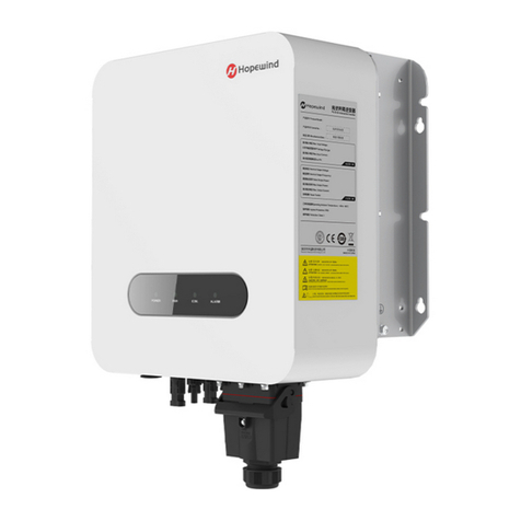
The hopeSun series string inverter is a three-phase string-type grid-connected inverter independently
developed by Hopewind Technology. Its main function is to convert the DC power generated by the PV
string into AC power and feed it into the power grid.
hopeSun 36KTL, hopeSun 40KTL and hopeSun 50KTL-M are 8-input string inverters;
hopeSun 50KTL is a 9-input string inverter;
hopeSun 60KTL, hopeSun 60KTL-M, hopeSun 70KTL and hopeSun 70KTL-M are 12-input string
inverters;
hopeSun 75KTL and hopeSun 80KTL-M are 14-input string inverters
Among them, hopeSun 50KTL-M, hopeSun 60KTL-M, hopeSun 70KTL-M and hopeSun 80KTL-M are
suitable for 500VAC/10kV (35KV) medium voltage grid-connected scenes, such as large-scale ground
photovoltaic power stations and distributed photovoltaic power plants above 400kW;
hopeSun 36KTL, hopeSun 40KTL, hopeSun 50KTL, hopeSun 60KTL, hopeSun 70KTL and hopeSun
75KTL are suitable for 400VAC low-voltage grid-connected scene, such as village-level photovoltaic
power station or industrial and commercial rooftop photovoltaic power station below 500kW.
2.1.1 Schematic
PV strings access the inverter to input DC; the MPPT circuits in the inverter track the maximum power
point inputted by PV string; then the inverter circuit invert the DC to the threes-phase AC.
The schematic diagrams are shown in following figures.
1+
2+
1-
2-
3+
4+
3-
4-
5+
6+
PE
Input EMI
filter
DC switch
Input EMI
filter
PE
MPPT
circuit
1#
MPPT
circuit
2#
MPPT
circuit
3#
BUS+
BUS-
RCD leakage
current
detection
N
A
B
C
fuse Current hall
5-
6-
7+
8+
7-
8-
Three-
phase
inverter
circuit
LC
filter
Output
EMI
filter
Figure 2-1 Schematic diagram of hopeSun 36KTL/40KTL
1+
2+
1-
2-
3+
4+
3-
4-
5+
6+
PE
Input EMI
filter
DC switch
Input EMI
filter
PE
MPPT
circuit
1#
MPPT
circuit
2#
MPPT
circuit
3#
BUS+
BUS-
RCD leakage
current
detection
PE
A
B
C
fuse Current hall
5-
6-
7+
8+
7-
8-
Three-
phase
inverter
circuit
LC
filter
Output
EMI
filter
Figure 2-2 Schematic diagram of hopeSun 50KTL-M

User Manual
6
1+
2+
1-
2-
3+
4+
3-
4-
5+
6+
PE
Input EMI
filter
DC switch
Input EMI
filter
PE
MPPT
circuit
1#
MPPT
circuit
2#
MPPT
circuit
3#
BUS+
BUS-
Three-
phase
inverter
circuit
LC
filter
RCD leakage
current
detection
Output
EMI
filter
N
A
B
C
fuse
Current hall
5-
6-
7+
8+
9+
7-
fuse
8-
9-
Figure 2-3 Schematic diagram of hopeSun 50KTL
1+
2+
1-
2-
3+
4+
3-
4-
5+
6+
PE
Input EMI
filter
DC switch
Input EMI
filter
PE
MPPT
circuit
1#
MPPT
circuit
2#
MPPT
circuit
3#
MPPT
circuit
4#
BUS+
BUS-
Three-
phase
inverter
circuit
LC
filter
RCD leakage
current
detection
Output
EMI
filter
N
A
B
C
fuse
Current hall
5-
6-
7+
8+
7-
8-
9+
10+
9-
10-
11+
12+
11-
12-
Figure 2-4 Schematic diagram of hopeSun 60KTL/hopeSun 70KTL
1+
2+
1-
2-
3+
4+
3-
4-
5+
6+
PE
Input EMI
filter
DC switch
Input EMI
filter
PE
MPPT
circuit
1#
MPPT
circuit
2#
MPPT
circuit
3#
MPPT
circuit
4#
BUS+
BUS-
Three-
phase
inverter
circuit
LC
filter
RCD leakage
current
detection
Output
EMI
filter
PE
A
B
C
fuse
Current hall
5-
6-
7+
8+
7-
8-
9+
10+
9-
10-
11+
12+
11-
12-
Figure 2-5 Schematic diagram of hopeSun 60KTL-M/hopeSun 70KTL-M

2 Product Description
7
13+
1+
13-
1-
2+
4+
2-
4-
5+
6+
PE
Input EMI
filter
DC switch
Input EMI
filter
PE
MPPT
circuit
1#
MPPT
circuit
2#
MPPT
circuit
3#
MPPT
circuit
4#
BUS+
BUS-
Three-
phase
inverter
circuit
LC
filter
RCD leakage
current
detection
Output
EMI
filter
Fuse Current hall
5-
6-
7+
8+
7-
8-
9+
10+
9-
11-
11+
12+
12-
14-
3+
3-
14+
10-
N
A
B
C
Figure 2-6 Schematic diagram of hopeSun 75KTL
13+
1+
13-
1-
2+
4+
2-
4-
5+
6+
PE
Input EMI
filter
DC switch
Input EMI
filter
PE
MPPT
circuit
1#
MPPT
circuit
2#
MPPT
circuit
3#
MPPT
circuit
4#
BUS+
BUS-
Three-
phase
inverter
circuit
LC
filter
RCD leakage
current
detection
Output
EMI
filter
PE
A
B
C
Fuse Current hall
5-
6-
7+
8+
7-
8-
9+
10+
9-
11-
11+
12+
12-
14-
3+
3-
14+
10-
Figure 2-7 Schematic diagram of hopeSun 80KTL-M
2.1.2 Operating mode
hopeSun three-phase string inverter has three working modes: standby mode, running mode, and
shutdown mode. The three mode switching conditions are shown in Figure 2-8.
Standby
mode
Running
mode Shutdown
mode
Running mode to standby mode:
Insufficient illumination or DC
switch disconnection detected
Standby mode to running
mode:
The light is sufficient and the
system is fault free
A fault occurrence or shutdown
command was detected
Standby mode to shutdown mode:
A fault occurrence or shutdown
command was detected
Shutdown mode to
standby mode:
Detected that the fault has
been cleared or the
power-on command
Figure 2-8 hopeSun 50KTL/40KTL operating mode

User Manual
8
Operating mode
Description
Standby
1) Standby mode mainly means that the external environment does not meet
the operating conditions of the inverter. If the light is insufficient, the DC input
switch is disconnected. In this mode, the inverter continuously self
-tests and
enters the
operating mode once the operating conditions are met.
2) In the standby mode, if the inverter detects a shutdown command or finds a
fault after the power-on detection, it enters the shutdown mode.
Operation
In the operating mode, the inverter converts the DC power of the PV string into
AC power and feeds it into the grid. The inverter performs MPPT operation to
output the maximum power of the PV string.
If the inverter detects a fault occurrence or shutdown command, it enters the
shutdown mode.
If it is de
tected that the PV string input power is lower than the grid-connected
power generation condition, it enters the standby mode.
Shutdown
If the inverter detects a fault occurrence or shutdown command during standby
or operation, it enters shutdown mode.
In
the shutdown mode, if the inverter detects that the fault has been cleared or
the power-on command, it enters standby mode.
2.2 System Configuration and Application
2.2.1 Application Description
Figure 2-9 shows the application diagram of the string inverter network, Figure 2-10 shows the design
scheme of the large-scale ground PV power plant, and Figure 2-11 shows the design scheme of the
distributed PV power plant.
Photovoltaic
panels String
inverter AC power
distribution unit Isolation
transformer Grid
Figure 2-9 Schematic diagram of string inverter application
Core exhanger
Optical fiber
ring network
Intelligent
data collector
String inverter
PV arrays
String inverter
PV arrays
Box-type
transformer Box-type
transformer
Intelligent
data collector
AC combiner
box AC combiner
box AC combiner
box AC combiner
box
Power grid
AC cable
DC cable
Com cable
Figure 2-10 Large-scale ground photovoltaic power plant networking design

2 Product Description
9
String inverter
PV arrays
Box-type
transformer
Power grid
User load
WiFi/GPRS
wireless module
Mobile
Internet
Internet
Internet
hopeCloud
hopeView
Client
Central monitoring center
Figure 2-11 Distributed photovoltaic power plant networking design
2.2.2 Supported grid form
hopeSun 36KTL, hopeSun 40KTL, hopeSun 50KTL, hopeSun 60KTL, hopeSun 70KTL and hopeSun
75KTL support the form of power grids TN-S, TN-C, TN-C-S, TT, IT;
hopeSun 50KTL-M, hopeSun 60KTL-M, hopeSun 70KTL-M and hopeSun 80KTL-M only support IT
form grid.
String
Inverter
L1
PE
L2
L3
N
PE
TN-S
L1
PE
L2
L3
PEN
TN-C
L1
PE
L2
L3
N
TN-C-S
PE PE
PE
PE
L1
PE
L2
L3
N
TT
PE PE
L1
L2
L3
IT
PE PE
String
Inverter String
Inverter String
Inverter String
Inverter
Figure 2-12 Schematic diagram of various grid forms
2.3 Naming Rules
hopeSun 80K TL - M
Rated output power:80K--80kW 70K--70kW
String inverter series
Outputside without isolation transformer
M:500Vac on-grid
None: 400Vac low voltage on-grid
Figure 2-13 Naming rules

User Manual
10
2.4 Nameplate label
(Note: The data is for reference only; please refer to the physical or technical agreement of the corresponding
product)
2.5 Machine configuration
This section shows the internal components of the string inverter, the back device, and the bottom
interface.
Note: hopeSun 36KTL, hopeSun 40KTL, hopeSun 50KTL-M and hopeSun 50KTL have same appearance,
there are 9 groups of PV terminal blocks at the bottom (36KTL, 40KTL and 50KTL-M only use 8 of them, the
used terminal blocks should be sealed);
hopeSun 60KTL, hopeSun 60KTL-M, hopeSun 70KTL, hopeSun 70KTL-M, hopeSun 75KTL and hopeSun
80KTL-M have same appearance, there are 14 groups of PV terminal blocks at the bottom (60KTL, 60KTL-M,
70KTL and 70KTL-M only use 12 of them, the used terminal blocks should be sealed).
CAUTION
There are components on the board that are very sensitive to static electricity. Anti-static measures must be
taken before touching the board.
When touching the board, be careful not to scratch the electrical components.

2 Product Description
11
1
3
2
No. Label Device name
1 LED indicator
2 Upper door
3 Lower door
Figure 2-14 Front view of the whole machine
The LED indicators from left to right are described as follows:
Table 2-1 LED Indicator Description
Indicator light Meaning Status Meaning
PV and grid
connection
Blue light on The voltage of PV side is more than 200V, and
the power grid connection is normal.
Blue light flash The grid connection is normal, but the input
voltage of PV side is less than 200V.
Blue light slow flash The input voltage of PV side is greater than 200V,
but the power grid is not connected.
Blue light off PV and power grid are not connected
Grid connected Blue light Inverter is in grid-connected start-up state
Blue light off Unconnected inverter start-up
Communication
indication
Blue light slow flash Normal communication
Blue light off Abnormal communication
Alarm indication
Red light slow flash Warning: Working instruction of PID power supply
Red light flash Abnormal Warning: Conventional Warning
Red light on Serious Alarm: Malfunction
Remarks:
Slow flash is defined as follows: 1 second bright, 2 seconds out;
Flash is defined as follows: 0.5 seconds bright, 0.5 seconds out.

User Manual
12
1
3
2
No. Label Device name
1 Handle
2 Mounting rack
3 Cooling fan
Figure 2-15 Back view of the whole machine
1
2
34
6
5
1
2
34
6
5
36KTL, 40KTL, 50KTL-M and 50KTL 60KTL, 60KTL-M, 70KTL, 70KTL-M, 75KTL and 80KTL-M
No Label Device name
1 DC SWITCH DC switch
2 1+ ~ 9(14)+ PV+ terminal block
3 1-~9(14)- PV- terminal block
4 AC OUTPUT AC output terminal
5 WiFi/GPRS communication interface
6 RS485 output terminal
Figure 2-16 The bottom diagram of the whole machine (interface description)
2.6 Identification on the package
On the outer packaging of the product, there are some labels to guide the user to transport and store the product.
The meanings indicated by the logo are as follows:
Do not stack or
backlog
Handle with care and avoid
damage caused by severe
collision or friction during
transportation.
Forbid
stampede
Pay attention to rain and
moisture-proof.
Other manuals for hopeSun Series
3
This manual suits for next models
10
Table of contents
Other Hopewind Inverter manuals
Popular Inverter manuals by other brands

Mitsubishi
Mitsubishi FR-A800 instruction manual

Tigo
Tigo ENERGY MODULE MAXIMIZER ES Series Installation and safety manual

CHNT Power
CHNT Power CPS SCA2KTL-PS1/EU Installation and operation manual

enphase
enphase Q 7 Micro Installation and operation manual

Envertech
Envertech EVT1600SE user manual

Nibe
Nibe SOLAR 41 Installer manual