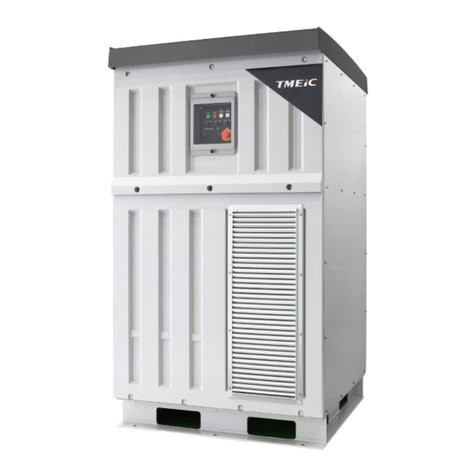
TMEIC TMdrive-30 User manual

6F3A4768
IGBT Inverter, IGBT Converter
TMdrive-30, TMdrive-P30
Instruction Manual
Oct, 2004
TOSHIBA MITSUBISHI-ELECTRIC
INDUSTRIAL SYSTEMS CORPORATION
TM_F50000B
© TOSHIBA MITSUBISHI-ELECTRIC
INDUSTRIAL SYSTEMS Corporation , 2004
All Rights Reserved.
StockCheck.com

— 1 —
6F3A4768
Maintenance, inspection, and adjustment of this equipment require specialized knowledge.
Read this manual completely and carefully before using this equipment.
Personnel who use this equipment should undergo specialized training provided by our
TMEIC on a for-fee basis.
Contact your TMEIC representative for details on training courses.
StockCheck.com

— 2 —
6F3A4768
Contents
1Usage Notes.................................................................................................................................................6
1.1 To Prevent Electric Shocks! ...................................................................................................................8
1.2 TMdrive-30 Inspection and Maintenance and Recovery Procedures ....................................................9
1.2.1
Inspection and Maintenance Procedure (Power-off Procedure)....................................................9
1.2.2
Recovery Procedure (Power-on Procedure)...............................................................................10
1.3 TMdrive-P30 Inspection and Maintenance and Recovery Procedures................................................11
1.3.1
Inspection and Maintenance Procedure (Power-off Procedure)..................................................11
1.3.2
Recovery Procedure (Power-on Procedure)...............................................................................12
1.4 Operation..............................................................................................................................................13
1.4.1
Normal operation of TMdrive-30................................................................................................13
1.4.2
Normal operation of TMdrive-P30 .............................................................................................13
1.4.3
Test operation (Common to TMdrive-30 and TMdrive-P30) .......................................................14
1.5 When a Fault Occurs ...........................................................................................................................15
1.6 Notes on Changing Parameter Settings ..............................................................................................17
2Overview.....................................................................................................................................................18
2.1 Introduction...........................................................................................................................................18
2.2 Description of Terminology ..................................................................................................................19
2.3 Specifications of TMdrive-30 and TMdrive-P30...................................................................................20
2.3.1
Features....................................................................................................................................20
2.3.2
General Specifications (Structure).............................................................................................21
2.3.3
General (Electrical) Specifications.............................................................................................22
2.3.4
TMdrive-30 Control Specifications (Speed sensor: PLG) ...........................................................23
2.3.5
TMdrive-P30 Control Specifications (Speed sensor: Resolver) ..................................................24
2.3.6
TMdrive-30 Control Specifications (Speed Sensor-less Vector Control).....................................25
2.3.7
TMdrive-30 Control Specifications (Speed Sensor-less Vector Control with Driving Multiple
Motors)......................................................................................................................................26
2.3.8
TMdrive-30 Control Specifications (V/f control) .........................................................................27
2.3.9
TMdrive-30 Control Specifications.............................................................................................28
2.3.10
Ratings......................................................................................................................................29
2.3.11
Protective Functions..................................................................................................................31
2.3.11.1
Current-related protection...........................................................................................33
2.3.11.2
Voltage Protection ......................................................................................................34
2.3.11.3
Motor Speed Protection (TMdrive-30).........................................................................34
2.3.11.4
Control Circuit and Power Supply ...............................................................................34
2.3.11.5
Protection Associated with Motor and Break (TMdrive-30) ..........................................35
2.3.11.6
Operation-related protection .......................................................................................36
2.3.11.7
Pre-charge-related protection (TMdrive-P30)..............................................................36
2.3.11.8
Grounding detection-related protection (TMdrive-P30)................................................36
2.4 Product Code........................................................................................................................................39
2.4.1
TMdrive-30................................................................................................................................39
2.4.2
TMdrive-P30 .............................................................................................................................40
3Interface......................................................................................................................................................41
3.1 Power System Interface and Grounding ..............................................................................................41
3.1.1
Power supply.............................................................................................................................41
3.1.1.1
TMdrive-30.................................................................................................................41
3.1.1.2
TMdrive-P30...............................................................................................................41
3.1.2
Grounding .................................................................................................................................41
3.2 Motor Interface (TMdrive-30) ...............................................................................................................43
3.2.1
One Motor.................................................................................................................................43
StockCheck.com

— 3 —
6F3A4768
3.2.2
Multiple Motors..........................................................................................................................43
3.3 Speed Sensor Interface (TMdrive-30)..................................................................................................44
3.3.1
PLG Interface (Differential Type)...............................................................................................44
3.3.2
Resolver Interface.....................................................................................................................45
3.3.3
Sensor-less Vector Control ........................................................................................................47
3.3.4
Speed Pulse Signal Output (Single end type) ............................................................................48
3.4 Serial Transmission..............................................................................................................................49
3.4.1
Transmission Types ..................................................................................................................49
3.4.2
TOSLINE-S20 Specifications ....................................................................................................51
3.4.2.1
TOSLINE-S20 Connections ........................................................................................51
3.4.2.2
Scan Transmission .....................................................................................................52
3.4.3
ISBus Transmission Specifications............................................................................................57
3.4.3.1
ISBus Connection.......................................................................................................57
3.4.3.2
Scan Transmission .....................................................................................................58
3.4.4
DeviceNet Transmission Specifications.....................................................................................61
3.4.4.1
DeviceNet Connection................................................................................................61
3.4.4.2
Scan Transmission .....................................................................................................63
3.4.5
PROFIBUS Transmission Specifications ...................................................................................69
3.4.5.1
PROFIBUS Connection ..............................................................................................69
3.4.5.2
Scan Transmission .....................................................................................................70
3.4.6
Sequence Input/Output..............................................................................................................73
3.4.6.1
Sequence Input ..........................................................................................................73
3.4.6.2
Sequence Output........................................................................................................76
3.4.6.3
Optional Sequence Output..........................................................................................78
3.4.7
Serial Input/Output Signals........................................................................................................79
3.4.7.1
Serial Input Signals.....................................................................................................79
3.4.7.2
Serial Output Signals..................................................................................................80
3.4.8
Message Transmission..............................................................................................................81
3.4.9
Transmission Error Detection ....................................................................................................81
3.4.9.1
Heartbeat ...................................................................................................................83
3.5 P I/O Input/output .................................................................................................................................84
3.5.1
P I/O Input.................................................................................................................................84
3.5.2
P I/O Output..............................................................................................................................88
3.6 Transmission Between Drives .............................................................................................................89
3.7 Motor Temperature Detection Circuit (TMdrive-30).............................................................................89
3.8 Analog Input/Output .............................................................................................................................90
3.8.1
Analog Input ..............................................................................................................................90
3.8.2
Analog Output ...........................................................................................................................92
3.8.2.1
General-purpose Analog Output .................................................................................92
3.8.2.2
Measurement Analog Output ......................................................................................94
3.9 Options (TMdrive-30) ...........................................................................................................................95
3.9.1
Motor Mounted Fan Circuit ........................................................................................................95
4Structure.....................................................................................................................................................96
4.1 Dimensions of TMdrive-30 ...................................................................................................................96
4.2 Dimension of TMdrive-P30 ..................................................................................................................97
4.3 Operation Panel....................................................................................................................................98
4.3.1
Equipment Model Name/Software Version Display .................................................................. 100
4.3.2
Operation Data Display ........................................................................................................... 100
4.3.3
Operation Preparation Display.................................................................................................101
4.3.4
FI (FIrst fault) Display..............................................................................................................102
4.3.5
FI Call .....................................................................................................................................102
4.3.6
Test Display ............................................................................................................................ 102
4.3.7
Software Resetting Operation.................................................................................................. 103
4.3.8
Software Error Display.............................................................................................................104
StockCheck.com

— 4 —
6F3A4768
4.3.9
Relief Mode Display ................................................................................................................ 104
5Operation..................................................................................................................................................105
5.1 Main Circuit Operation .......................................................................................................................105
5.1.1
Main circuit Operation of Two-level Inverter ............................................................................ 105
5.1.2
Two-level Converter Operation................................................................................................108
5.1.3
Main Circuit Operation for Three-level Inverter........................................................................110
5.1.4
Three-level Converter Operation ............................................................................................. 113
5.2 Main Circuit Configuration of TMdrive-30 ..........................................................................................115
5.2.1
Single Drive (1500kVA, 2000kVA)........................................................................................... 115
5.2.2
Twin-drive (2x1500kVA, 2x2000kVA) ......................................................................................116
5.3 Main Circuit Configuration of TMdrive-P30........................................................................................117
5.3.1
Single Converter (1700kW) ..................................................................................................... 117
5.3.2
Twin converter (2x1700kW) .................................................................................................... 118
5.4 Control Circuit TMdrive-30 .................................................................................................................119
5.4.1
Speed Reference .................................................................................................................... 120
5.4.2
Speed Control ......................................................................................................................... 122
5.4.2.1
Speed Control 1 (ASPR)........................................................................................... 122
5.4.2.2
Speed control gain switching (option)........................................................................123
5.4.2.3
Speed Control 2 (ASR) .............................................................................................124
5.4.2.4
Speed Control with RMFC Control (ASRR) ............................................................... 126
5.4.3
Torque Reference and Current Reference ...............................................................................128
5.4.3.1
Tension Control (Option) ..........................................................................................128
5.4.3.2
IQ Limit .................................................................................................................... 129
5.4.4
D-Q Axis Current Control......................................................................................................... 130
5.4.5
Voltage Reference................................................................................................................... 132
5.4.6
Speed Feedback ..................................................................................................................... 133
5.4.6.1
PLG.......................................................................................................................... 133
5.4.6.2
Resolver...................................................................................................................134
5.5 Optional Function According to Application (TMdrive-30) .................................................................135
5.5.1
Auto Field Weakening Control.................................................................................................135
5.5.2
Torque Control ........................................................................................................................136
5.5.3
Sensor-less Vector Control ...................................................................................................... 139
5.5.4
V/f Control...............................................................................................................................139
5.5.5
JOG Operation........................................................................................................................140
5.5.6
Emergency Operation ............................................................................................................. 141
5.5.6.1
Emergency Operation Mode ..................................................................................... 141
5.5.6.2
E-HOLD Mode.......................................................................................................... 141
5.5.7
Shared Motion.........................................................................................................................142
5.6 Control Circuit TMdrive-P30...............................................................................................................144
5.6.1
Voltage reference....................................................................................................................145
5.6.2
Voltage Control ....................................................................................................................... 145
5.6.3
D-Q Axis Current Control......................................................................................................... 146
5.6.4
Voltage Reference................................................................................................................... 148
5.6.5
Voltage Saturation Restraint Control (VSC) .............................................................................149
5.6.6
Reactive Current Voltage Control (RCV) (Optional) ................................................................. 150
6Maintenance (Common to TMdrive-30 and TMdrive-P30) ..................................................................151
6.1 Daily Inspections ................................................................................................................................151
6.2 Regular Inspections............................................................................................................................152
6.3 Points of Maintenance........................................................................................................................152
6.3.1
Cleaning of Main Circuit and Control Circuit ............................................................................ 152
6.3.2
Enclosure and Structural Parts ................................................................................................153
6.3.3
Printed Circuit Boards .............................................................................................................153
6.4 Parts to be Regularly Renewed .........................................................................................................154
StockCheck.com

— 5 —
6F3A4768
6.5 Recommended Spare Parts...............................................................................................................155
6.6 Prohibition of Modifications ................................................................................................................159
6.7 Movement...........................................................................................................................................159
6.8 Disposal..............................................................................................................................................159
7Data Control (Common to TMdrive-30 and TMdrive-P30) ..................................................................160
7.1 Setting Data........................................................................................................................................160
8Fault and Recovery (Common to TMdrive-30 and TMdrive-P30).......................................................161
8.1 Cautions when Handling Fault ...........................................................................................................161
8.2 Traceback...........................................................................................................................................162
8.3 How to Repair.....................................................................................................................................163
8.3.1
Cautions on Repair.................................................................................................................. 163
8.3.2
Replacing Units.......................................................................................................................163
8.4 Restoring Setting Parameters............................................................................................................163
8.4.1
Reloading (Personal Computer Tool).......................................................................................163
StockCheck.com

— 6 —
6F3A4768
1 Usage Notes
This equipment includes high-voltage components. To prevent electric shock, burns, or other injuries when
using this equipment, and to maintain its performance, be sure to read this manual before using this equipment.
Also, observe all warning labels attached to the equipment.
The and marks have the following meanings:
Danger (Red Label) [Warning Label Examples]
Failure to avoid locations or actions marked in this
manner may lead to serious injury or death.
Warning (Orange Label)
Failure to avoid locations or actions marked in
this manner may lead to injury, albeit of a
somewhat lesser severity. Failure to follow these
directions may also lead to property loss, such as
damage to the equipment or components, or to
fires.
: Electric shock warning : Warning for safe work
DANGER
Hazardous voltage can result in electric
shock.
Make sure that there is no electrical charge
before inspection or maintenance.
WARNING
Hazardous voltage can result in
electric shock.
Do not open the door while the
power is on.
Turn off the power supply to the
equipment before inspection or
maintenance.
DANGER
Primary circuit voltage
is supplied.
WARNING
Hazardous voltage can result in electric
shock.
Do not open the door while the power
is on.
Opening the door during power receiving
will trip the circuit breaker.
StockCheck.com

— 7 —
6F3A4768
Notice (Green Label) [Warning Label Examples]
These labels provide advice that can assure safe
operation, can prevent errors and performance
degradation in the equipment, and can be useful in
preventing breakdowns.
Others (White Labels)
These labels present items related to
maintaining the performance of the equipment.
NOTICE
When operating or adjusting the
equipment and during maintenance/
inspections, be sure to observe the
precautions noted in the User's
Manual.
The following are guidelines for
the replacement of parts.
PARTS
GUIDELINES
FOR
REPLACEMENT
COOLING FAN 3 YEARS
ELECTROLYTIC
CAPACITOR 7 YEARS
POWER SUPPLY
UNIT 7 YEARS
FUSE 7 YEARS
StockCheck.com

— 8 —
6F3A4768
1.1 To Prevent Electric Shocks!
The inverter (TMdrive-30) has 1250 V ac or more,
1800 V dc or more and 200 V ac or 220/230 V ac
circuits, and the converter (TMdrive-P30) has 1100 V
ac or more, 1800 V dc or more and 200 V ac or
220/230 V ac circuits, which are extremely
dangerous. Do not remove the protective covers
designed for shock prevention at any time other than
inspection and maintenance.
Do not touch internal parts with wet hands.
Do not touch the inside panel or parts of the
equipment while the power is being applied
or the motor is running.
StockCheck.com

— 9 —
6F3A4768
1.2 TMdrive-30 Inspection and Maintenance and Recovery Procedures
1.2.1 Inspection and Maintenance Procedure (Power-off Procedure)
(1) Stop the load equipment, and verify that all electrically powered equipment has
stopped completely.
(2) Turn on the operation panel interlock switch by pressing it. Prohibit operation of the
inverter on the hardware (safety or emergency stop switch, etc).
(Note) When a common DC power supply is used, make sure that all devices
connected to the DC power supply have been stopped.
(3) Before starting the inspection and maintenance of the inverter, stop the common
power supply panel supplies to the equipment and move the circuit breaker to the
safety area to prevent it from being turned on accidentally (safety maintenance in
twice).
(4) Wait for at least five minutes.
(5) Make sure that the charge lamp on the inverter panel is off.
(6) Turn off the control power supply MCCB ("CONTROL").
(7) Unlock the door padlock.
(8) Remove the screws (two places) on the front door of the inverter panel and open
the door with the door handle.
(9) Use a voltage checker and the like to check that the main circuit and the control
circuit are already discharged.
(10) Measure the voltage between check pins HIGH-LOW on the GDM board to check
the main circuit voltage is at a safe level.
(11) Measure the voltage between check pins P-CTR-OV-CTR on the GDM board to
check the control power supply voltage is at a safe level.
(12) Perform safety measures (grounding, etc) according to need
(13) When the unit (IPU*) is replaced, see the Unit Replacement Manual (document No.
6F3A4795).
* IPU: An abbreviation for IGBT Power Unit
Stop the
equipment
Turn off the main
power supply
Turn off the
control power
supply
Check the
voltage
Replacement/
Maintenance
Work
StockCheck.com

— 10 —
6F3A4768
1.2.2 Recovery Procedure (Power-on Procedure)
(1) Before turn on the power supply, check the DC power supply is off.
(2) Check the recovery status of the sections that were disconnected for inspection and
maintenance and the replaced parts (connector insertion status, conductor
tightening status, etc.)
(3) Release of the safety measures (grounding, etc).
(4) Check that operations of all supplied inverters are prohibited on the hardware
(safety or emergency stop switch, etc).
(5) Check that front doors of all supplied inverter panels are closed and the screws
(two places) are tightened.
(6) Close the front door of the inverter panel and tighten the screws (two places).
(7) Lock the door padlock.
(8) Turn on the control power supply MCCB ("CONTROL").
Note: Check that there is no error detected.
(9) Check that Fault or Alarm isn’t displayed on the operation panel on the automatic
control panel. If Fault or Alarm is displayed, check the fault message and then
recovery it.
(10) Turn on the DC power supply unit main power.
(Note) When a common DC power supply is used, check that all devices connected
to the DC power supply are ready to receive power.
(11) Check the safety of the system and release of the operation prohibited on the
hardware (safety or emergency stop switch, etc).
Prepare the
equipment
for operation
Turn on the
control power
supply
Close the
door and
tighten the
screws
Turn on the
DC power
supply unit
Check
before
receiving
power
StockCheck.com

— 11 —
6F3A4768
1.3 TMdrive-P30 Inspection and Maintenance and Recovery Procedures
1.3.1 Inspection and Maintenance Procedure (Power-off Procedure)
(1) Check that all supplied inverters have stopped completely then turn off the "AC
MAIN CIRCUIT BREAKER" switch on the automatic control panel to stop the
equipment and to turn off move the circuit breaker. In addition, move the circuit
breaker to the safety area to prevent it from being turned on accidentally (safety
maintenance in twice).
(2) Check that the "ON" LED is off (unlit) and the "OFF" LED is on (lit) on the automatic
control panel.
(3) Prohibit operation of the converter on the hardware (safety or emergency stop
switch, etc).
(4) Wait for at least five minutes.
(5) Make sure that the charge lamp on the inverter panel is off.
(6) Turn off the control power supply MCCB ("CONTROL"). The “OFF” LED on the
automatic control panel turns off (unlit).
(7) Unlock the door padlock.
(8) Remove the screws (two places) on the front door of the converter panel and open
the door with the door handle.
(9) Use a voltage checker and the like to check that the main circuit and the control
circuit are already discharged.
(10) Turn off the control power supply MCCB ("CONTROL"). The “OFF” LED on the
automatic control panel turns off (unlit)
(11) Measure the voltage between check pins HIGH-LOW on the GDM board to check
"the main circuit voltage is at a safe level.
(12) Perform safety measures (grounding, etc) according to need
(13) When the unit (IPU*) is replaced, see the Unit Replacement Manual (document No.
6F3A4795).
* IPU: An abbreviation for IGBT Power Unit
Stop the
equipment
Turn off the
control power
supply
Check the
voltage
Turn off the main
power supply
Replacement/
Maintenance
Work
StockCheck.com

— 12 —
6F3A4768
1.3.2 Recovery Procedure (Power-on Procedure)
(1) Before turn on the power supply, check the DC power supply is off.
(2) Check the recovery status of the sections that were disconnected for inspection and
maintenance and the replaced parts (connector insertion status, conductor
tightening status, etc.)
(3) Release of the safety measures (grounding, etc).
(4) Check that operations of all supplied inverters are prohibited on the hardware
(safety or emergency stop switch, etc).
(5) Check that front doors of all supplied inverter panels are closed and the screws
(two places) are tightened.
(6) Close the front door of the converter panel and tighten the screws (two places).
(7) Lock the door padlock.
(8) Turn on the control power supply MCCB(“CONTROL”).
The “OFF” LED on the automatic control panel turns off (lit).
(Note) Check that there is no error detected.
(9) Check that Fault or Alarm isn’t displayed on the operation panel on the automatic
control panel. If Fault or Alarm is displayed, check the fault message and then
recovery it.
(10) Check the safety of the system and release of the operation prohibited on the
hardware (safety or emergency stop switch, etc).
(11) When the "AC MAIN CIRCUIT BREAKER" switch on the automatic control panel is
turned on, the pre-charge automatically starts. (If pre-charge does not start,
examine the items for which the electrical condition (UV) is not satisfied and satisfy
the condition.) During pre-charge, the "ON" LED on the automatic control board
blinks.
(12) The pre-charge completes in about 10 seconds. Upon completion of pre-charge,
the main power supply is turned on automatically. When the main power supply is
turned on, the "ON" LED on the automatic control board turns on (lit).
(This procedure is applicable only when the circuit breaker automatic interface is
provided (See Section 5.3). The circuit breaker can be operated in one of the
following three ways; from the main automatic control panel, from the circuit
breaker panel, or remotely.)
Turn on the
control power
supply
Close the door
and tighten the
screws
Check
before
receiving
power
Pre-charge
Turn on the
main power
supply
StockCheck.com

— 13 —
6F3A4768
1.4 Operation
Be sure to strictly adhere to the power-on procedure and power-off procedure (See Sections 1.2 and1.3).
Otherwise unnecessary stress will be incurred.
PROHIBITION
While the equipment is in operation and the motor
is running, do not turn off the main circuit power
supply or control power supply under any
circumstances.
Do not disconnect any unit during operation.
1.4.1 Normal operation of TMdrive-30
Normal operation through interface should be performed by the following procedure after confirming that the
necessary interface signals are securely connected.
(1) Set the speed command signal to the lowest state.
(2) Turn on the IL (Interlock) input signal and EXT (operation command) input signal.
(3) As the speed command signal is increased gradually, the motor rotates at a rate proportional to the speed
command signal. If the motor does not rotate normally, check the wiring of the main circuit inverter output
circuit and the speed detector again.
As for the rotational direction of the motor, the forward rotational direction differs depending on the machine
to drive. See the schematic diagram. To reverse the rotational direction, set the polarity of the speed
reference to negative. To reverse the rotational direction (forward rotation) by the positive speed reference,
reverse the polarity of the setting value of $CS_MOTOR_RPM, turn off the control power supply once then
turn it on again. Do not change the wiring of the resolver and the main circuit.
(4) If you turn off the EXT signal during rotation, the motor will slow down and stop.
1.4.2 Normal operation of TMdrive-P30
Normal operation through interface should be performed by the following procedure after checking that the
necessary interface signals are securely connected.
(1) Set the given voltage reference.
(2) Turn on the IL (Interlock) input signal and EXT (operation command) input signal.
(3) When the main power supply is turned on following the procedure in Section1.3.2, the operation ready
(READY) condition is satisfied and the operation starts.
(4) If you turn off the EXT signal during operation, the converter stops.
StockCheck.com

— 14 —
6F3A4768
1.4.3 Test operation
Test operation can be done using the maintenance tool.
Before performing test operation, check the following items:
(1) Check that the necessary signals are securely connected.
(2) Check that operation on the main unit side is off and the equipment is completely stopped.
(3) Contact the person in charge of field operations and obtain permission for individual operations.
After checking the above items, perform test operation.
The test mode shown in Table 1.4.1 is available for test operation.
Table 1.4.1 Test Mode
Test mode No. Name Purpose
TEST-22 Speed step response To check the response of speed control by stepping up
speed reference.
TEST-25 Load response To check the response of speed control by stepping up
torque reference.
TEST-26 Flux current step To check the response of current control by stepping up
flux current reference.
TEST-29 Acceleration/Deceleration
response
To check the acceleration / deceleration response in
internal acceleration / deceleration rate by stepping up
speed reference input.
In order to use the test mode, operate the drive in the following procedure. Refer to the operation manual of
the support tool for the usage of a step response function.
(1) Check the operation of the drive equipment is off. The drive equipment cannot enter the test mode while
that is in operation.
(2) Select a required test mode by using step response function of the support tool. When the test mode is
chosen, the drive equipment enters the test mode (panel ready lump is blinking).
Set step value and step time in step response function.
(3) Operate the drive equipment at the motor speed which the test is performed (TEST-22,25).
Turn on the flux current by inputting operation command (EXT) etc (TEST-26).
Stand-by the motor acceleration by inputting operation command (EXT) (TEST-29).
(4) Push the step start button of step response function to perform the step response.
(5) After step response is finished, obtained data is displayed on the support tool.
Repetitive step response can be performed.
(6) Push test finish button of step response function to finish the test mode.
In addition, the test mode has an interlock as shown below.
▪The drive equipment cannot enter the test mode while that is in operation.
▪When the test mode except TEST-22 and TEST-25 is used, the drive equipment cannot finish
the test mode unless operation of the drive equipment is turned off.
StockCheck.com

— 15 —
6F3A4768
1.5 When a Fault Occurs
When a serious fault occurs, perform the following procedure to prevent further damage and to return the
equipment to service as soon as possible.
(1) Record the fault message displayed on the operation panel.
<Standard type operation panel>
Fault code (number) appears after “Fl-”.
“FI-“ display
Display change
Fault code (number) display
Fault code, fault symbol and their explanation are shown in the Fault Code Table on the next page.
<High function type operation panel>
Fault symbols (alphabet) are displayed. In order of fault occurrences, from first to tenth faults are displayed.
If the right arrow or enter button is pressed, it will alternate a comment display.
Active Fault Display
1.FUSE_ 62
2.BLR_ 159
3.AC_MCCB_ 155
4.UVA 222
5.UV_READY 287
--- RESET FAULT NOW ---
Active Fault Display
1.IGBT Fuse 62
2.E Critical Fault 159
3.AC In MCCB Opn 155
4.E Ready Cnd Met 222
5.Elect Cond Met 287
--- RESET FAULT NOW ---
(2) Collect the trace back data.
Collect the data recorded in the non-volatile memory in the unit.
The latest 6 or 7 portions of trace back data are stored.
PC that maintenance tool is installed (option) can replay the trace back data.
(3) Check the apparent operating state of the equipment.
Perform the safety check described earlier before performing this check.
In addition, to recover from the fault, see "8 Fault and Recovery".
• Only use parts stipulated by Toshiba as replacements. Use of any parts other than those stipulated by
Toshiba may result in the equipment not being able to perform as desired, and also may result in safety
problems. If there are no spare parts on hand, order parts from Toshiba, or have Toshiba replace the
parts.
• This equipment includes parts that require periodic replacement. See "6.4 Parts to be Regularly
Renewed", for details. Be sure to order these parts in advance, since delivery may take time.
The three digits code appears after “Fl-” on the standard operation panel is indicated in Table 1.5.1.
• When a fault occurs, please wait for 30 seconds before “Fault-reset-operation”.
StockCheck.com

— 16 —
6F3A4768
Table 1.5.1 List of Fault Code
No. Symbols No. Symbols No. Symbols No. Symbols No. Symbols
48 OCA 129 MPSF 208 UVS 301 SPA1 376 OL_A
49 OCD_U 130 OVP 209 IL 302 SPA2 377 CL_TA
50 OCD_V 131 OVN 210 P_SW 306 P_SW 378 GR_A
51 OCD_W 132 OVP_B 211 QSTOP_FAULT 307 QSTOP_FAULT 379 PRE_F
52 OH_T_U 133 OVN_B 212 RDIR_PROT 308 RDIR_PROT 380 CUR_DIFF
53 OH_T_V 134 GDM_F_U 213 PLL_ERR 309 PLL_ERR 381 M_FN
54 OH_T_W 135 GDM_F_V 214 MPSFA 310 MPSFA 382 GR_T
56 F_UP 136 GDM_F_W 215 ACSW_F 311 ACSW_F 383 STPRQ
57 F_VP 137 GDM_F_B_U 219 ACSW _F_B 315 ACSW_F_B 384 AIN_FAULT
58 F_WP 138 GDM_F_B_V 221 UVA_EX 317 UVA_EX 386 SOFT_STL
59 F_UN 139 GDM_F_B_W 222 UVA 318 UVA 388 OH_U
60 F_VN 141 OCA 223 C_IL 320 AIN_FAULT 389 OH_V
61 F_WN 142 OCA_B 224 AIN_FAULT 322 TL_F3 390 OH_W
64 OCA_B 143 PLL 226 TL_F3 323 TL_F4 391 OH_B_U
65 OCD_B_U 145 UVD 227 TL_F4 324 M_FN_T 392 OH_B_V
66 OCD_B_V 146 OL5 230 M_OH 325 BR_F 393 OH_B_W
67 OCD_B_W 147 OL20 231 B_HLTY 326 M_OH 398 GR
68 OH_T_B_U 150 CL_T 235 TUNE_IL 327 B_HLTY 399 SPA1
69 OH_T_B_V 151 C_FN_T 237 SPA1 331 TUNE_IL 400 ACSW_C
70 OH_T_B_W 152 ACOFF 238 SPA2 333 SPA1 401 ACSW_C_B
72 F_UP_B 153 ACP_T 240 SPA1 334 SPA2 402 GATE_U
73 F_VP_B 154 DCSW 241 SPA2 335 GR_T 403 GATE_V
74 F_WP_B 155 AC_MCCB 246 UVPSIL 336 STL_A 404 GATE_W
75 F_UN_B 159 BLR 247 ACSW_C 337 C_FN 405 GATE_U_B
76 F_VN_B 161 UVD_B 250 UVNSIL 339 C_FN_B 406 GATE_V_B
77 F_WN_B 167 C_FN_T_B 251 ACSW_C_B 340 OH_ACL 407 GATE_W_B
82 OSS 170 DCSW_B 253 M_FN 341 MTMP_S 409 SPA3
83 OSS_FO 171 AC_MCCB_B 254 SP_SIL 342 M_OH 410 VDC_IL
86 SP_ERR 176 UVP_B 255 STCMD 343 M_OH_A 411 PRE_CTT_IL
87 SP_ERR2 177 UVN_B 256 GDM_F_U 344 OL_A 412 ACP
89 CURU 178 UVP 257 GDM_F_V 345 CL_TA 413 UVPSIL
90 CURW 179 UVN 258 GDM_F_W 346 GR_A 414 UVNSIL
91 CURU_B 180 OH_ACL_T 259 GDM_F_B_U 347 PRE_F 415 UV
92 CURW_B 181 PRECHG_OH 260 GDM_F_B_V 348 CUR_DIFF 416 ACSW_T
96 F_C 182 SYS_ERR 261 GDM_F_B_W 349 M_FN 417 ACSW_T_B
97 F_C_B 183 PARA_ERR 262 GATE_U 350 GR_T 425 DS
99 GP_F 185 AC_NL 263 GATE_V 352 AIN_FAULT 426 SPA4_T
109 F_GND 186 GR_T 264 GATE_W 354 SOFT_STL 427 SPA4
110 F_PRE 187 PHASE_ERR 265 GATE_U_B 356 OH_U 428 UV
112 PLD_ERR 188 BLA 266 GATE_V_B 357 OH_V 429 P_SW
115 DS_T 189 STALL 267 GATE_W_B 358 OH_W 430 BLR
116 BLR_FAULT 191 UPS_ERR 272 TL_F1 359 OH_B_U 431 BLR_CPSF
117 CPU_A 194 TL_F1 273 TL_F2 360 OH_B_V
118 CPU_M 195 TL_F2 274 TL_F3 361 OH_B_W
120 SPA4_T 199 N_IM 275 TL_F4 366 GR
121 SPA3_T 200 SPA4_T 279 TQZ_GB 367 SPA1
122 SPA2_T 201 SPA3_T 282 ACSW_T 368 STL_A
123 SPA1_T 202 SPA2_T 287 UV_READY 369 C_FN
124 SPA4 203 SPA1_T 288 RNTD_C 371 C_FN_B
125 SPA3 204 SPA4 292 M_FN_T 372 OH_ACL
126 SPA2 205 SPA3 293 BR_F 373 MTMP_S
127 SPA1 206 SPA2 295 CHG_START 374 M_OH
128 CPSF 207 SPA1 298 ACSW_T_B 375 M_OH_A
For details of the fault codes, see the troubleshooting manual (6F3A4791).
StockCheck.com

— 17 —
6F3A4768
1.6 Notes on Changing Parameter Settings
The setting data for this equipment is stored in EEPROM that is nonvolatile memory, as shown in Fig. 1.6.1.
When the microcontroller is started (initialized) at power on the data in EEPROM is read as indicated by (1) and
that data is copied without change to RAM as indicated by (2). From that point on, the data in RAM is used to
control the system as indicated by (3).
Microcontroller
RAM
•Execution parameters
EEPROM
•Saved parameters
(1)
(2)
(3)
(4)
(5)
(6)
Initialization
Parameters copied to RAM.
Control software
Parameter modifications from
the personal computer
[Important]
Parameter save operation
Fig. 1.6.1 Memory Structure for Parameter Settings
When modifying the parameter settings from maintenance tool on the personal computer, the execution
parameters in RAM are modified. A "Set point control" operation is required to save those values. If this
operation is not performed, the previous values will be restored the next time the system is initialized.
The write operation that saves the parameters (from RAM to EEPROM) may require up to dozens of seconds to
complete. In addition, user comments can be attached to the setting value stored in EEPROM. Write time differs
depending on the number of parameters and thus make sure to wait until the user comment will be registered
(displayed) on the screen as EEPROM comment in the storage area. If the control power supply is turned off
during this operation, both the RAM and the EEPROM parameters may be set to incorrect values. If incorrect
values are stored, an error state (“Pl-183” will be displayed) will occur the next time the control power supply is
turned on, and it may become impossible to drive the motor normally. If this error state occurs, read "8 Fault and
Recovery" and follow those directions to recover from the problem.
Make sure that you never cut off the control power
when writing of the setting value to the parameter storage area “EEPROM” begins
until the user comment appears in the “EEPROM” area on the personal computer screen.
StockCheck.com

— 18 —
6F3A4768
2 Overview
2.1 Introduction
TMdrive-30 is a totally digital- and vector-controlled sine wave PWM inverter that performs highly precise and
efficient variable speed control of AC motors with a small to medium capacity. Also, TMdrive-P30 is an IGBT
converter that receives the AC power supply and converts it into the DC power for the IGBT inverter. This
equipment is power supply system-friendly because it controls the input current as sin wave. Before starting
operation of this equipment, thoroughly read this instruction manual to fully understand its contents.
This manual consists of the specifications of the equipment, names of blocks, concept of control, startup and
operation of the equipment, fault and recovery, maintenance points, and describes maintenance and operation
after the installation of the equipment.
○
Interfaces
For the connections with external equipment, read "3 Interface”.
○
Concept of control
To know how this equipment performs variable speed control over motors, read "5 Operation".
○
Startup and operation of equipment
For the procedure for preparations before starting the equipment and how to operate the equipment
independently on an experimental basis or how to check the operation status during line operation, read "1.4
Operation".
○
Maintenance
For the inspection points to keep the equipment in optimal conditions and cautions on handling internal parts,
read "6 Usage Notes”.
○
Fault and recovery
For action to be taken in the case of any fault in the equipment, read "8 Fault and Recovery".
○
Spare parts
For spare parts for emergency replacement, read "6.5 Recommended Spare Parts".
StockCheck.com

— 19 —
6F3A4768
2.2 Description of Terminology
This section describes the special terms used in this manual.
Table 2.2.1 Description of Terminology
Technical Term Meaning and its contents
3-level inverter Inverter that enables 3 levels of output.
The output phase voltage has three levels: (+), (0), and (-).
CTR circuit board Main control circuit board
EEPROM An abbreviation of Electrical Erasable Programmable Read Only Memory
GDM circuit board Gate Drive Module
A gate drive circuit board that amplifies gate signals to turn on/off the IGBT.
IGBT An abbreviation of Insulated Gate Bipolar Transistor
LCD An abbreviation of Liquid Crystal Display
LED An abbreviation of Light Emitting Diode
MCCB An abbreviation of Molded Case Circuit Breaker
NPC Another name for a 3-level converter
An abbreviation for Neutral Point Clamped
PP7 Power electronics Processor Various Inverter control Integration (VII = 7) Toshiba’s
32-bits microcomputer for power electronics control
PSM Switching power supply unit that outputs
±
15 V dc and
+
5 V dc.
RAM An abbreviation of Random Access Memory
TOSLINE-S20 Optical transmission device (Toshiba's product name). Exchanges operating
sequence signals and operation data with an external device equipped with this
transmission device.
Initialize An initialization process.
In this equipment, as the control power is turned from off to on, the data and circuits
are initialized.
Interface A method that exchanges signals between this equipment and external equipment.
Inverter A reverse conversion circuit that converters DC main power voltage into AC voltage.
(DC
→
AC conversion)
Inverter unit A box containing IGBT inverter circuit and gate drive circuit board.
Converter unit A box containing the IGBT converter circuit and gate drive circuit board.
Overload A status, in which the current output from this equipment, exceeds the continuous
rating of this equipment.
Converter A conversion circuit that receives AC power and converts it to DC voltage (AC
→
DC
conversion).
A reversible converter also allows inverter operation but the converter connected on
the power supply side is called a converter.
Common converter DC main circuit power supply for TMdrive-30. This unit is used as common power
supply.
TMdrive-P30, TMdrive-T30, and TMdrive-D30 series are provided.
Operation panel A panel used for data display and basic operation.
Load A motor that receives the power from TMdrive-30
ASC An abbreviation for ACTIVE STAR COUPLER. Equipment that performs
transmission signal branching for the Toshiba optical transmission device
TOSLINE-S20.
TOSLINE-S20 Optical transmission device (Toshiba's product name). Exchanges operating
sequence signals and operation data with an external device equipped with this
transmission device.
StockCheck.com
This manual suits for next models
1
Table of contents
Other TMEIC Inverter manuals
Popular Inverter manuals by other brands
TECO-Westinghouse
TECO-Westinghouse E510 Start-up and installation manual

Growatt
Growatt NEO 1200-2000M-X Quick installation guide

Kaco
Kaco Powador 3200 operating instructions

AES
AES 3100S-PKG Installation, operation, and programming manual
Toshiba
Toshiba TOSVERT VF-AS1 Series instruction manual
Lux Power Technology
Lux Power Technology SNA5000WPV user manual
