Hopewind hopeSun Series User manual


hopeSun Series
String Inverter
(8KTL~33KTL)
User Manual
Version: V1.0
Thank you for purchasing products developed and manufactured by Shenzhen Hopewind
Technology Co., Ltd. (hereinafter referred to as “Hopewind”). Hope our products and this manual
can meet your demands. Any suggestion for improvement shall be appreciated.
Shenzhen Hopewind Technology Co., Ltd. reserves the copyright of this manual, and it shall be
subject to change without any further notice.

About this manual
For Readers
This manual is helpful for technicians who install, debug, operate and maintain string inverters of
Hopewind. Please read this manual carefully before operates the product.
Readers are required to know the basic knowledge about electric components, wiring, signs and
mechanical drawings.
Outlines
Chapter
Contents
1 Safety Precautions
This chapter describes the safety precautions when transporting, storing, installing,
running and maintaining the Inverter.
2 Product Description
This chapter describes the basic principles, naming rules, product configuration and
data.
3 System Installation
This chapter describes the unpacking inspection, installation tools, installation
environment, reserved space, fixing method, cable connection.
4 Commissioning
Guide
This chapter describes the inspection before startup, Commissioning and startup of
string inverter.
5 Maintenance and
Troubleshooting
This chapter describes the daily maintenance methods, maintenance intervals and
troubleshooting of the product.
6 Inverter handling
Guide
This chapter describes the basic requirements and precautions when disassembling,
replacing, and scrapping the inverter.
Warning Signs in This Manual
It shows that there is a significant potential danger. If the operation is not performed
according to requirements, serious injury or damage may be caused to people or
equipment.
It shows that there is a general potential danger. If the operation is not performed
according to requirements, general injury or damage may be caused to people or
equipment.
It shows that there is a general potential danger. If the operation is not performed
according to requirements, general injury or damage may be caused to equipment.
Terms and Abbreviations
Terms/Abbreviations
Description
MPPT
Maximum Power Point Tracking
Photovoltaic string
Multiple solar cell arrays in parallel or series.
EEPROM
Electrically Erasable Programmable Read-Only Memory
hopeInsight
A monitoring and debugging software for inverter.
Version Description
Version
Release Date
Description
V1.0
2021-8-5
The first version

Content
About this manual........................................................................................................................... 5
1 Safety Precautions.......................................................................................................................1
1.1 Transportation.....................................................................................................................................1
1.2 Storage................................................................................................................................................ 1
1.3 Installation........................................................................................................................................... 2
1.4 Operation.............................................................................................................................................2
1.5 Maintenance....................................................................................................................................... 3
2 Product Description.................................................................................................................... 5
2.1 Product Description........................................................................................................................... 5
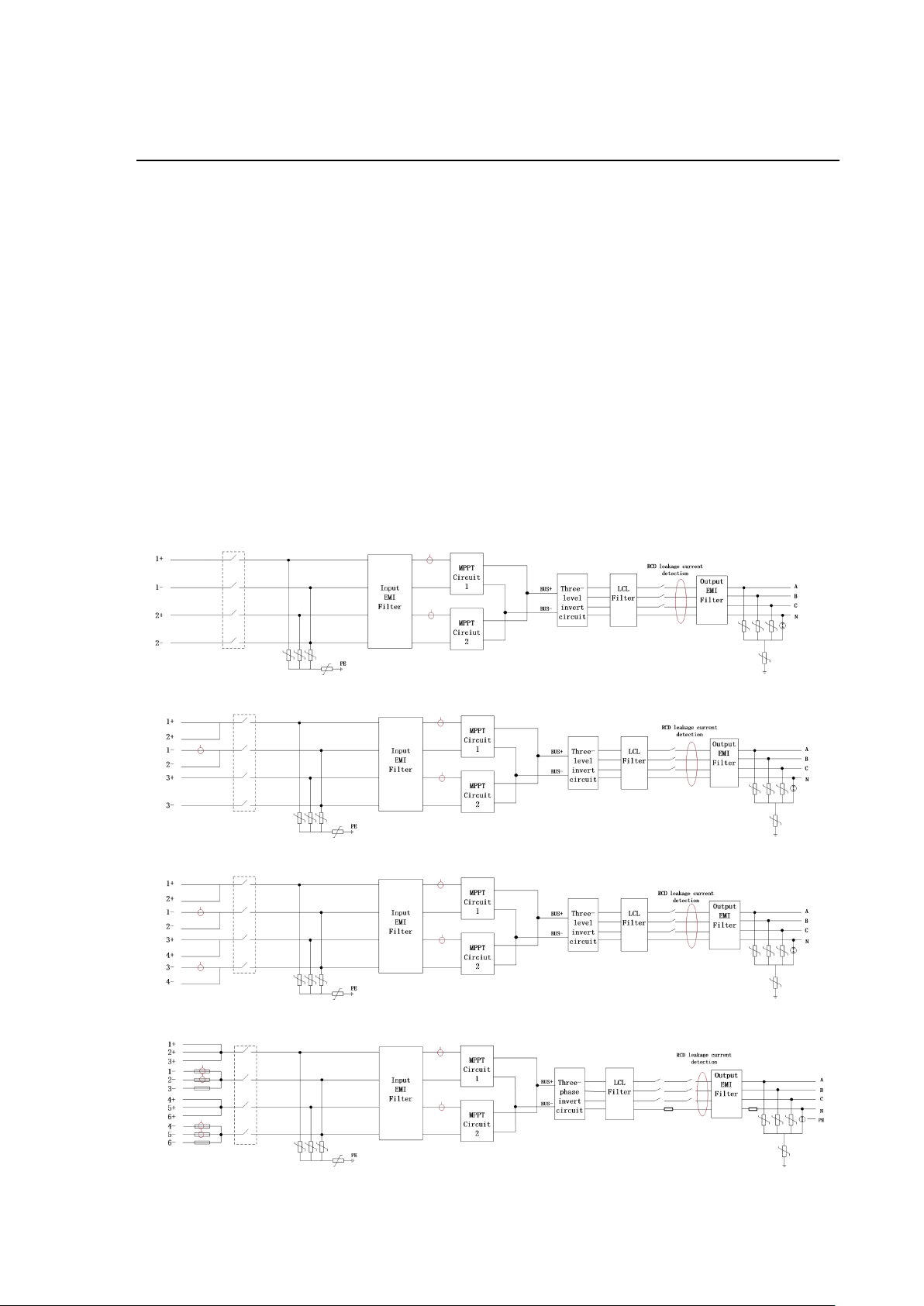
2.1.1 Schematic Diagram......................................................................................................................... 5
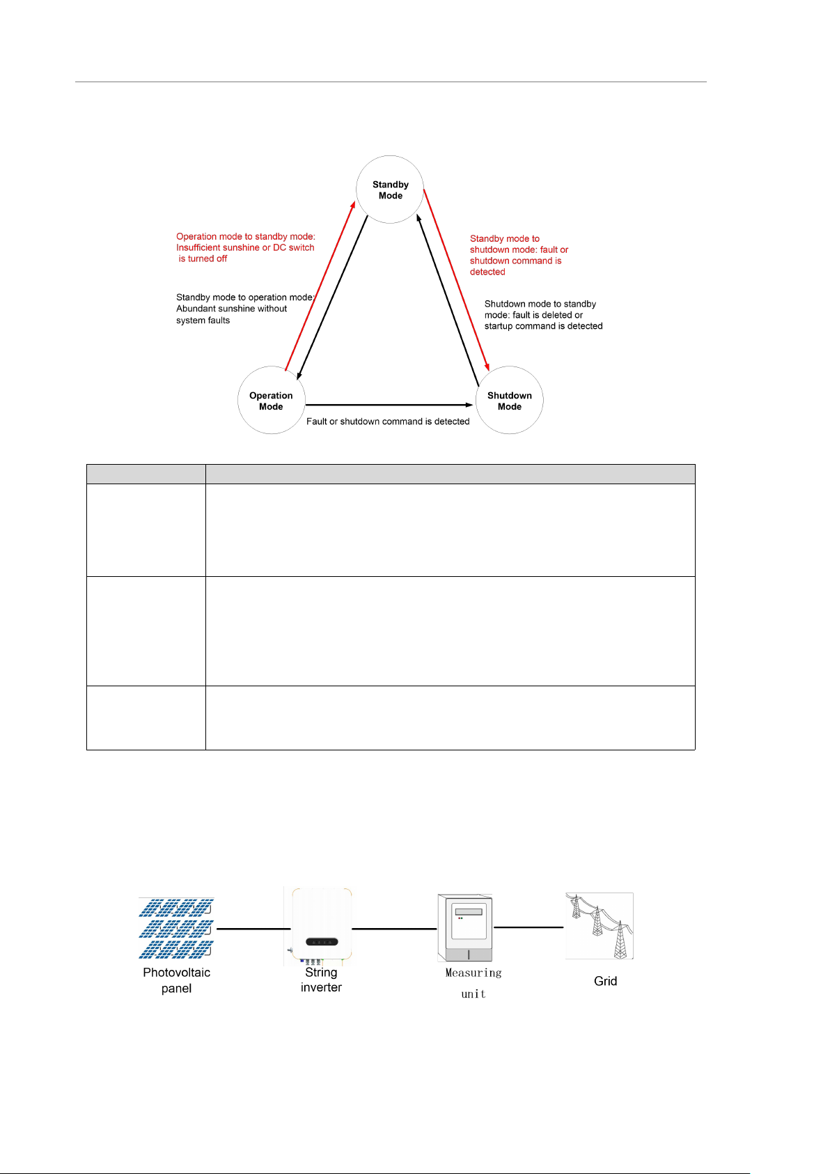
2.1.2 Operation Mode............................................................................................................................... 6
2.2 System Configuration and Application............................................................................................6
2.2.1 Application Description....................................................................................................................6
2.2.2 Supported Grid Form...................................................................................................................... 7
2.3 Naming Rules..................................................................................................................................... 7
2.4 Nameplate label................................................................................................................................. 8
2.5 Machine Configuration...................................................................................................................... 9
2.6 Signs and labels...............................................................................................................................11
2.7 Warning Labels in Inverter..............................................................................................................11
2.8 Technical Data..................................................................................................................................12
2.9 Mechanical Parameters.................................................................................................................. 14
2.10 Ambient Requirements................................................................................................................. 14
3 System installation.................................................................................................................... 17
3.1 Unpack and inspection....................................................................................................................17
3.2 Preparation of installation tools..................................................................................................... 17
3.3 Installation environment requirements......................................................................................... 17
3.4 Requirements for reserved space.................................................................................................18
3.5 Fixing method...................................................................................................................................19
3.6 Electrical connection....................................................................................................................... 20
3.6.1 Cable requirements.......................................................................................................................20
3.6.2 Recommended cable specifications...........................................................................................20
3.6.3 Torque requirements..................................................................................................................... 21
3.6.4 Preparation before operation.......................................................................................................21
3.6.5 Connect the ground wire.............................................................................................................. 22
3.6.6 Connect the AC output cable.......................................................................................................22
3.6.7 Connect the communication cable............................................................................................. 24
3.6.8 Connect DC input cables............................................................................................................. 25
4 Commissioning Guide.............................................................................................................. 27
4.1 Check before starting......................................................................................................................27
4.2 Power on the system.......................................................................................................................28
4.3 Power off the system.......................................................................................................................28
5 Maintenance and troubleshooting........................................................................................ 29
5.1 Maintenance items and cycle........................................................................................................ 29
5.2 Troubleshooting................................................................................................................................30
6 Inverter handling instructions................................................................................................ 35
6.1 Disassembly of the inverter............................................................................................................35
6.2 Replace the inverter........................................................................................................................ 35
6.3 Package the inverter....................................................................................................................... 35
6.4 Scrapped the inverter......................................................................................................................35

1
1Safety Precautions
This chapter describes the safety precautions to be observed during the installation, operation
and maintenance of inverter. Please carefully read the safety precautions before the installation,
maintenance and other operations of inverter. All personals must strictly observe safety
precautions during the operation. Personal injury or damage to inverter and associate devices
may occur if the safety precautions are ignored.
When operating the inverter, please pay particular attention to the following items:
1. Only qualified professionals can install, operate and maintain the inverter.
2. Please avoid toppling and knocking the inverter cabinet during moving the inverter.
3. Prevent liquid, debris or chippings from getting inside the inverter; a conductive fluid and debris may cause
an internal short circuit of inverter and result in equipment damage.
4. Before completing installation and maintenance, the inverter must be isolated from power grid and other
electrified devices.
5. Please make sure that relevant protective measures have been taken to avoid electric shock, fire or other
accidents.
Don't place explosive and inflammable substances around the inverter!
1.1 Transportation
1. Please keep the inverter well packed and upward, avoid strong shock or collision during the transportation.
2. Please transport the inverter with package and operate in accordance with the signs and labels during the
transportation. Please refer to "2.6 Signs and labels" for detailed information.
3. Please ensure the transportation environment can meet the requirements. Please refer to "2.10 Ambient
Requirements" for detailed information.
1.2 Storage
The storage environment of inverter should meet the corresponding requirements. Please refer to "2.10
Ambient Requirements" for detailed information.
About long-term storage:
Before or after the installation, it's regarded as long-term storage if the inverter has been in the no power
supply status for over three weeks. Please pay attention to the following issues about long-term storage:
Put the desiccant into several equipment cabinets and pack the inverter with packaging materials;
Attention must be paid to ventilation and moisture prevention where equipment is stored and any water is
strictly prohibited;
Necessary measures must be taken to deal with adverse environments, such as abrupt cooling and
heating, collision and dust storm to prevent damages to the inverter.
Regular inspection at least once a week, inspect whether the package is intact and prevent it from
damages caused by insects and rats. Please replace the damaged package immediately.
The inverter shall be unpacked, inspected, repacked, and replace the new desiccant if it is stored for over

User Manual of String Inverter
2
half a year.
Don't store the inverter without package.
1.3 Installation
1. The DC switch and breaker of the inverter must be cut off and the inverter shell must be reliably grounded
before any operation is conducted inside the inverter.
2. The inverter must be grounded canonically and the dimension of grounding conductor must conform to the
requirements of security specifications to ensure the personal safety.
3. Don't place explosive and inflammable substances around the inverter.
1. The installation environment of the inverter must have good ventilation and heat dissipation, the inverter
can’t expose to the sunlight directly.
2. It's advised to fix the inverter by four personals to avoid mechanical injury. Please take safety measures to
prevent injury during installation.
3. Liquid, dust or debris must be prevented from entering the inverter during installation and maintenance as
conducting liquid and debris may cause short circuit inside the inverter, thus damaging the equipment.
4. Please ensure the installing torque of power cable is proper during the wiring of external cables and
inverter, excessive torque will damage the screw, and too small torque will increase the contact resistance
and result in overheating.
5. The terminal of the power cable connected with the inverter must comply with national standard as
substandard terminal or disqualified construction may lead to overheating of the power cable and outbreak
of fire in severe cases.
6. Installation place must meet the operation environment requirements. Please refer to "2.10 Ambient
Requirements" for detailed information.
1.4 Operation
1. During the operation of inverter, the cabinet door of inverter needs to be locked to avoid electric shock and
other personnel injuries, which can also prevent salinity, water, dust or other conducting materials in the air
from entering into inverter.
2. Please keep the surrounding environment of operating inverter non-corrosive.
3. Don't place explosive and inflammable substances within two meters from the inverter.
4. Don't touch the internal board, components, cables and terminal blocks of inverter during the powering on.
5. When there are faults or abnormal smell or sound, turn off the DC switch and open the breaker of AC side
immediately.
1. Power on the inverter only after completing the installation and properly connecting the cables.
2. Do not conduct any insulation resistance test or high-voltage resistance test for inverter, because wrong
test may cause damages to inverter.
3. Cut off wiring between inverter and external equipment when conducting insulation and voltage resistance
test for external equipment.

1 Safety Precautions
3
1.5 Maintenance
c
1. Please cut off the AC side breaker first, then cut off the DC switch, and wait for at least 5 minutes before
performing maintenance.
2. Please prevent irrelevant personals from entering maintenance scene during the maintenance.
3. Please maintain the inverter under the condition of understanding this manual and being equipped with
proper tools and test devices.
4. Please wear insulating gloves and safety shoes for you safety.
Regular check and maintenance must be performed, please refer to "5 Maintenance and troubleshooting" for
details.
--Chapter End--

5
2Product Description
2.1 Product Description
hopeSun series three-phase string on-grid inverter is independent developed by Hopewind.
it's main function is converting DC current generated by PV arrays into AC current and feeding it
into the grid.
hopeSun 8KTL/10KTL/12KTL are 2-input string inverters. hopeSun 15KTL/17KTL are 3-input
string inverters. hopeSun 20KTL/22KTL/25KTL are 4-input string inverters. hopeSun
30KTL/33KTL are 6-input string inverters. These products only suit for 400VAC low-voltage
grid-connected scenarios, such as village-level photovoltaic power stations below 400KW or
industrial and commercial rooftop photovoltaic power stations.
2.1.1 Schematic Diagram
hopeSun 8KTL/10KTL/12KTL are connected to the inverter through 2 PV string inputs.
hopeSun 15KTL/17KTL are connected to the inverter through 3 PV string inputs. hopeSun
20KTL/22KTL/25KTL are connected through 4 PV string inputs In the inverter. hopeSun
30KTL/33KTL are connected to the inverter through 6 PV string inputs. There are 2 MPPT circuits
inside the inverter for MPPT tracking of the strings, and then the inverter circuit realizes DC
conversion to three-phase Alternating current as he schematic diagram below.
Figure 2-1 Two-input string inverter system schematic diagram
Figure 2-2 Three-input string inverter system schematic diagram
Figure 2-3 Four-input string inverter system schematic diagram
Figure 2-4 Six-input string inverter system schematic diagram

User Manual of String Inverter
6
2.1.2 Operation Mode
hopeSunHV string inverter includes three operation modes: standby mode, operation mode
and shutdown mode. The three mode switching conditions are shown in Figure 2-5.
Figure 2-5 hopeSun string inverter operation mode
Operation Mode
Description
Standby
1) Standby mode mainly refers to the external environment doesn't meet the operation
condition, such as insufficient sunshine or DC switch is turned off. Under this mode, the
inverter continuously performs self-checking and enters operation mode once the
operation conditions are satisfied.
2) Under standby mode, the inverter will enter shutdown mode after detecting the
shutdown command or faults.
Operation
1) Under the operation mode, the inverter converts DC current of photovoltaic arrays into
AC current and feeds it to the grid. The inverter performs MPPT arithmetic and outputs
the maximum power of photovoltaic arrays.
2) The inverter will enter shutdown mode after detecting the faults or shutdown
command.
3) The inverter will enter standby mode after detecting the input power of photovoltaic
arrays is lower than the on-grid power generation condition.
Shutdown
1) If the inverter detects a fault occurrence or shutdown command during standby or
operation mode, it enters shutdown mode.
2) In the shutdown mode, if the inverter detects that the fault has been cleared or the
power-on command, it enters standby mode.
2.2 System Configuration and Application
2.2.1 Application Description
Figure 2-6 shows the application diagram of the string inverter network, Figure 2-7 shows the
design scheme of the distributed PV power plant.
Figure 2-6 Application diagram of the string inverter network

2 Product Description
7
Figure 2-7 Design scheme of the l distributed PV power plant
2.2.2 Supported Grid Form
hopeSun 8KTL~hopeSun 33KTL support the TN-S, TN-C, TN-C-S,TT IT systems in Figure
2-8.
Figure 2-8 Schematic diagram of IT system
2.3 Naming Rules
Figure 2-9 Naming rules

User Manual of String Inverter
8
2.4 Nameplate label
(Note: The data is for reference only; please refer to the physical or technical agreement of the
corresponding product for actual parameters)

2 Product Description
9
2.5 Machine Configuration
This section describes the internal components, back device, and bottom interface of the
string inverter. Bottom structure may differ from other models, the 30KTL is taken as an example
here.
There are components on the board that are sensitive to static electricity. Anti-static measures must be
taken before touching the board.
When touching the board, please be careful to avoid scratching the electrical components.
No.
Label
Component Name
1
LED indicator
2
AC cable shield
Figure 2-10 Front view of the inverter
The LED indicators from left to right are described as follows:
Table 2-1 LED Indicator Description
Indicator light
Meaning
Status
Meaning
PV and grid
connection
Blue indicator
lights on
DC voltage is more than 200V and grid is connected
normally.
Blue indicator
flashes
DC voltage is more than 200V (grid is not
connected).
Blue indicator
lights off
At least 1 PV array is normally connected.
On-grid
operation
Blue indicator
lights on
The inverter is in the on-grid status.
Blue indicator
lights off
The inverter is not connected to the grid.
Communication
indication
Blue indicator
flashes
Normal communication.
Blue indicator
lights off
Abnormal communication.
Alarm
indication
Red indicator
flashes slowly
PID is operating.
Red indicator
flashes
Abnormal alarm: regular alarm.
Red indicator
Critical alarm: faults.

User Manual of String Inverter
10
lights on
Remarks:
Slow flash is defined as: 1 second lights up, 2 seconds lights off.
Flash is defined as: 0.5 seconds lights up, 0.5 seconds lights off.
No.
Label
Component Name
1
Hanging Bracket
2
DC Switch
Figure 2-11 Back view of the inverter
No.
Label
Component Name
1
1+ ~ 6+
PV+ terminals
2
1- ~ 6-
PV- terminals
3
Anti-backflow terminal
4
WiFi/GPRS communication interface
5
AC OUTPUT
AC terminal
6
Fan
Figure 2-12 Bottom view of the inverter
Note: HopeSun 8KTL/10KTL/12KTL has only 2 PV inputs at the bottom, hopeSun 15KTL/17KTL
has 3 inputs, hopeSun 20KTL/22KTL/25KTL has 4 inputs, and hopeSun 30KTL/33KTL has 6
inputs. HopeSun models of 17KTL and below have no cooling fan at the bottom.

2 Product Description
11
2.6 Signs and labels
On the outer packaging of the product, there are some labels to guide the user to transport
and store the product. The meanings indicated by the labels are as follows:
Do not stack or
backlog
Handle with care and
avoid damage caused by
severe collision or friction
during transportation.
Forbid stampede
Pay attention to rain and
moisture-proof.
Stand upright and do
not tilt
Prohibition of tilting or
turning products
Front facing of the
inverter
Back facing of the
inverter
2.7 Warning Labels in Inverter
In order to ensure the safety of the person and property when using the product and to avoid
accidents, the following warning labels may be provided inside and outside the body of the string
inverter to remind the user of the safety precautions during operation.
PE: Here is the protective grounding terminal, requires reliable grounding to ensure the
safety of operators and equipment.
Warning: This component may present a hazard other than high voltage, which the user
should pay attention to.
High voltage hazard: This component may present a high voltage hazard and the user
must pay special attention.
Hot surface: Pay attention to the hot surface to prevent burns.
Refer to the user manual: Please refer to the corresponding instructions in the user
manual before operation.
Discharge identification: This equipment has an energy storage device. Before
maintenance, it is necessary to wait for the energy storage device to discharge to prevent
electric shock. The waiting time is not less than the indicated discharge time.

User Manual of String Inverter
12
2.8 Technical Data
Model
hopeSun
8KTL
hopeSun
10KTL
hopeSun
12KTL
hopeSun
15KTL
hopeSun
17KTL
DC
parameters
Maximum DC voltage
1100V
Starting Voltage
200V
MPPT Voltage Range
200V~1000V
MPPT Range Full Load
370V~850V
450V~850V
Max. Input Current of Each
MPPT
20A / 20A
26A / 20A
Max. short-circuit current
30A / 30A
39A / 30A
Number of DC Inputs
1 / 1
2 / 1
MPPT Number
2
AC
parameters
Rated Output Power
8kW
10kW
12kW
15kW
17kW
Max. Active Power (cosθ=1)
8.8kW
11kW
13.2kW
16.5kW
18.7kW
Rated Output Voltage
400V (Three Phase) (380V optional)
Operating Voltage Range
300V~480V
Rated Output Current
11.6A
14.5A
17.4A
21.7A
24.6A
Max. Output Current
12.7A
16.0A
19.1A
23.9A
27.0A
Rated Grid Frequency
50Hz / 60Hz
Power Factor
0.8 (Leading) ~ 0.8 (Lagging)
THD
<3%
System
parameters
Max. Efficiency
98.60%
98.61%
98.62%
European Efficiency
98.30%
AC/DC SPD
Yes
Insulation Impedance
Detection
Yes
Residual Leakage Current
Detection
Yes
PV String Fault Detection
Yes
Output Overcurrent Protection
Yes
Protection Degree
IP65
Operating Temperature Range
-25℃~ +60℃
Cooling System
Natural Cooling
Smart Air Cooling
Standby Power Consumption
<1W
Topology Structure
Transformerless
Operating Altitude
4000m (Derating above 3000m)
Display
LED Indicator + APP
Communication
WiFi / GPRS / 4G
DC & AC Terminator
DC:MC4 AC:OT/ DT
Certification
EN50549 / IEC61683 / IEC62109 / IEC61000 / IEC62116 /
IEC61727 / CQC / CGC
Optional
WiFi&GPRS Module / Anti-PID Module / Anti-Reversed Module
Mechanics
Parameters
Dimensions (H*W*D)
380*400*247mm
Weight
≤22kg

2 Product Description
13
Model
hopeSun
20KTL
hopeSun
22KTL
hopeSun
25KTL
hopeSun
30KTL
hopeSun
33KTL
DC
parameters
Maximum DC voltage
1100V
Starting Voltage
200V
MPPT Voltage Range
200V~1000V
MPPT Range Full Load
425V~850V
Max. Input Current of Each
MPPT
30A / 30A
40A / 40A
Max. short-circuit current
45A / 45A
60A / 60A
Number of DC Inputs
2 / 2
3 / 3
MPPT Number
2
AC
parameters
Rated Output Power
20kW
22kW
25kW
30kW
33kW
Max. Active Power (cosθ=1)
22kW
24.2kW
27.5kW
33kW
36.3kW
Rated Output Voltage
400V (Three Phase) (380V optional)
Operating Voltage Range
300V~520V
Rated Output Current
28.9A
31.8A
36.1A
43.5A
47.6A
Max. Output Current
31.8A
35.0A
39.7A
47.6A
52.4A
Rated Grid Frequency
50Hz / 60Hz
Power Factor
0.8 (Leading) ~ 0.8 (Lagging)
THD
<3%
System
parameters
Max. Efficiency
98.63%
98.65%
98.94%
99.00%
98.80%
European efficiency
98.30%
AC/DC SPD
Yes
Insulation Impedance Detection
Yes
Residual Leakage Current
Detection
Yes
PV String Fault Detection
Yes
Output Overcurrent Protection
Yes
Protection Degree
IP65
Operating Temperature Range
-25℃~ +60℃
Cooling System
Smart Air Cooling
Standby Power Consumption
<1W
Topology Structure
Transformerless
Operating Altitude
4000m (Derating above 3000m)
Display
LED Indicator + APP
Communication
WiFi / GPRS / 4G
DC & AC Terminator
DC:MC4 AC:OT/ DT
Certification
EN50549 / IEC61683 / IEC62109 / IEC61000 / IEC62116 /
IEC61727 / CQC / CGC
Opcional
WiFi&GPRS Module / Anti-PID Module / Anti-Reversed Module
Mechanics
Parameters
Dimensions (H*W*D)
380*450*247mm
Weight
≤25kg
≤30kg
≤35kg

User Manual of String Inverter
14
2.9 Mechanical Parameters
Size and weight
Model
W*H*D (mm)
Net weight (kg)
hopeSun 8KTL
380*450*245
≤22
hopeSun 10KTL
hopeSun 12KTL
hopeSun 15KTL
hopeSun 17KTL
hopeSun 20KTL
≤25
hopeSun 22KTL
hopeSun 25KTL
≤30
hopeSun 30KTL
≤35
hopeSun 33KTL
Note: size does not contain hangers, handles, pads, and so on. Dimensional error: ± 10mm.
Inverter structure size
Note: The model shown in the picture below is 30KTL. The inverter sizes of other models are
similar, only the sizes of AC protection shell may be different.
Figure 2-13 hopeSun series inverter and hanging board size (left, front, back, unit: mm)
2.10 Ambient Requirements
Transportation environment
Requirements
Type of shipping
Waterways, railways, highways, aviation, etc.
Ambient temperature
-25℃~+70℃
Relative humidity
≤95% when the temperature is +40℃
Mechanical conditions
The vibration should not exceed the following limits:
2Hz≤f<9Hz, displacement 7.5mm;
9Hz≤f<200Hz, acceleration 20m/s2;
200Hz≤f<500Hz, acceleration 40m/s2;
Storage environment
Requirements

2 Product Description
15
Transportation environment
Requirements
Storage place
Store in a warehouse with air circulation, no harmful gases, no flammable and
explosive substances, and no corrosive substances. Avoid strong mechanical
vibration and impact; stay away from strong magnetic fields.
Ambient temperature
-25℃~+70℃
Relative humidity
≤95%
Mechanical conditions
The vibration should not exceed the following limits:
10Hz≤f<57Hz, displacement 0.075mm;
57Hz≤f<150Hz, acceleration 10m/s2;
Working environment
Requirements
Normal operating state
Shut down state
Installation site
Usually installed outdoors, at the bottom of the photovoltaic module.
Do not install the inverter in areas where flammable and explosive
substances are stored.
Avoid direct sunlight, rain and snow to extend the life of the inverter. It is
recommended to install in a sheltered place. If it can’t be satisfied,
please build a sunshade.
Ambient temperature
-25℃~+60℃(After exceeding
45 ℃, the maximum continuous
input power and branch current
will be derated)
-25℃~+70℃
Relative humidity
≤100%, allow internal condensation
Altitude
≤4000m, must be derated above 3000m
Mechanical conditions
Vibration should not exceed the following limits:
10Hz≤f<57Hz, displacement 0.075mm;
57Hz≤f<150Hz, acceleration 10m/s2;
-- Chapter end --

17
3System installation
3.1 Unpack and inspection
After confirming that the outer packaging is intact, please perform unpacking inspection.
Unpack the box and check whether the appearance of the string inverter is good. When opening
the packing box, you need to use tools carefully to avoid scratching the string inverter;
The string inverter has been rigorously tested and inspected at the factory, but accidental
damage may occur during transportation, so please check the string inverter immediately after
receiving the goods. If you find any damage or omissions, please contact Hopewind Technology
as soon as possible, our staff will serve you as soon as possible.
3.2 Preparation of installation tools
Tool or equipment
Use
Remarks
4#Allen wrench
Disassembly and assembly of the lower
door panel of the inverter
Phillips screwdriver (PH2)
Loosen/tighten the screws of the output
terminals and baffles
Bolt spec: M6,M8
Tube terminal crimping pliers
Crimp the communication cable
terminal
/
Socket wrench
AC wiring
Bolt spec: M8
MC4 Terminal crimping pliers
Crimp MC4 terminal
The input cable needs to be crimped
into the MC4 terminal before it can
be connected to the PV + / PV-
terminal on the string inverter.
MC4 Removal tool
Remove MC4 terminal
/
Wire stripper
Stripping wire
/
Multimeter
Measure voltage to ensure safety
during wiring and installation
/
Safety protective equipment
Labor protection necessary for
construction
Insulation shoes, gloves, etc.
3.3 Installation environment requirements
The environmental requirements for the installation of string inverters are shown in "2.10
Ambient Requirements".
The installation method and position must be suitable for the weight and size of the string
inverter, see "2.9 Mechanical Parameters ".
The string inverter should be installed in a well-ventilated environment to ensure good heat
dissipation. Protect the inverter from direct sunlight, rain and snow can extend the life of the
inverter. It is recommended to choose a sheltered installation site. If it cannot be satisfied,
please build a sunshade (optional accessory).
During the operation of the string-type inverter, the temperature of the chassis and heat sink
will be relatively high, please installed the inverter in a location where it will not be accidentally
touched.
Note: This chapter takes hopesun 30KTL as an example to introduce the cable connection
methods for installation. The interfaces of other models may be a bit different, so please connect
cables according to actual situation while referring to this chapter.

User Manual of String Inverter
18
3.4 Requirements for reserved space
When installing string inverters, proper space must be reserved around the string inverters to
facilitate heat dissipation and maintenance.
Figure 3-1 Installation space of string inverter
When multiple string devices are installed on the same plane, it is recommended to install in a
straight line.
Figure 3-2 Installation space of string inverter
If you need to install it in two rows, it is recommended to install them in the shape of triangle.
Figure 3-3 Installation space of string inverter
Other manuals for hopeSun Series
3
This manual suits for next models
10
Table of contents
Other Hopewind Inverter manuals