manuals.online logo
Brands
  1. Home
  2. •
  3. Brands
  4. •
  5. Hopewind
  6. •
  7. Inverter
  8. •
  9. Hopewind hopeSun Series User manual

Hopewind hopeSun Series User manual

hopeSun Series
60KTL, 60KTL-M,
70KTL, 70KTL-M,
75KTL, 80KTL-M
String Type PV Inverter
Quick Installation Guide
CAUTION
1.The contents of this manual are subject to irregular updates
due to product upgrades or other reasons. Unless otherwise
agreed, this manual is only used as guidance. All statements,
information and recommendations in the document do not
constitute any express or implied warranty.
2.In any case, guidance in this manual cannot replace safety
warnings and instructions on user manuals and product
fuselage.
3.All operations of the equipment must be carried out by
professionals. Operators should be fully familiar with the
composition, working principles and standards of the whole
PV system.
4.Before installing the equipment, check whether the delivery is
complete and whether the body has obvious external damage
according to the "packing list". If there are any missing items
or any damage, please contact the distributor.
5.The following two situations occur and are not covered by the
warranty.
Remove the tamper-evident label;
Equipment damage caused by failure to store, handle,
install, and use the equipment in accordance with the
requirements of this manual and the user manual.
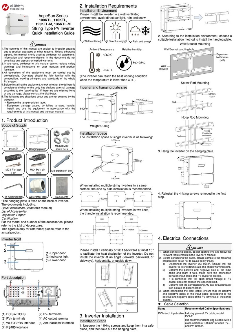
1. Product Introduction
Scope of Supply
Inverter Hanging plate* M8 screw sets
M8 expansion bolt
MC4 PV- jack
+ pin
4# Allen wrench Waterproof lock Documents
MC4 PV+ pin
+ jack
*The hanging plate is fixed on the back of inverter.
The documents including:
Quick Installation Guide (this manual)
List of Accessories
Inspection Report
Certification
For the model and number of the accessories, please
refer to the List of Accessories.
This figure is only for reference; please refer to the
actual product.
Inverter Front
1
3
2
(1) Upper door
(2) Indicator light
(3) Lower door
Port Description
1
2
34
6
5
(1) DC SWITCH
(2) PV+ terminals
(3) PV- terminals
(4) AC output terminal
(5) Wi-Fi/GPRS interface
(6) RS485 interface
2. Installation Requirements
Installation Environment
Please install the inverter in a well ventilated
environment, avoid direct sunlight, rain and snow.
√Well ventilated ×Direct sunlight ×Rain and snow
≤60℃
≥-40℃
Ambient Temperature Relative humidity
5%~95%
(The inverter can reach the best working condition
when the temperature is lower than 40℃)
Inverter and hanging plate size
705mm
650mm
285mm
Weight≤75kg
400mm
207mm
Installation Space
The installation space of single inverter is as following:
≥500mm
≥300mm
≥500mm
≥200mm
≥1000mm
When installing multiple string inverters in a same
surface, the side by side installation is recommended.
≥300mm ≥300mm
When installing multiple string inverters in two lines,
the triangle installation is recommended.
≥100mm ≥300mm ≥100mm ≥300mm
Please install it vertically or tilt it backward at most 15°
to facilitate the heat dissipation of the inverter. Do not
install the inverter at an angle (forward, backward, or
sideways), horizontally, or upside down.
X
√
<15°
√
X
3. Inverter Installation
Installation Steps
1. Unscrew the 4 fixing screws and keep them in a safe
place, and then take out the hanging plate.
2. According to the installation environment, choose a
suitable installation method to install the hanging plate.
Wall/Bracket Mounting
Wall/
Bracket
Expansion
bolt/screws
(M8)
Wall/Bracket punching hole
Screw Rod Mounting
Rod
Screws
(M8)
Hoop Rod Mounting
Rod
Hoops
(Provided by
customers)
3. Hang the inverter on the hanging plate.
4. Reinstall the 4 fixing screws removed in the first
step.
4.Electrical Connections
DANGER
1. When connecting cables, do not operate live and follow the
relevant requirements in the Inverter's User Manual.
2. Before connecting the cable, please complete the following
preparations so as not to cause bodily injury.
(1) Disconnect the inverter DC switch. Ensure that the
inverter is in shutdown state and attach warning signs.
(2) Confirm the positive and negative pole of the input
cable and mark it well. Make sure the connection
between input cable and PV cluster is broken.
(3) It is confirmed that the open circuit voltage of PV
cluster does not exceed the specified limit.
(4) Confirm that the corresponding AC box circuit breaker
is in a state of disconnection.
3. When connecting the input cable, ensure that the positive
and negative poles of the input cable correspond to the
positive and negative poles of the PV terminals of the series
inverter.
Cable Selection
Name
Recommended Cable Specifications
PV branch
input cable
Industry general PV cable, model: PV1-F
It is recommended to use a cable with a
cross-section of 4.0 mm2 for each PV+ and PV-
branch.
AC output
cable
4 core outdoor cable (A, B, C, N) or 3 core
outdoor cable (A, B, C)
Recommended cross sectional area of
conductor (copper):35mm2
RS485
communication
cable
It is recommended to use a special
communication cable or 4-core or 2-core
shielded twisted pair cable with a
cross-sectional area of not less than 0.75mm2.
PE ground
cable
It is recommended to use at least one grounded
dedicated cable with a cross-sectional area of
16 mm2.
Note:
1. The AC output has only 1 waterproof locks with a specification
of 42mm~50mm. When the screw is locked, use the sleeve to
calibration.
2. The RS485 communication cable has only one waterproof
lock and the size is 18mm~25mm.
Output side cable connection
1. Crimping the OT terminal. Users need to prepare
the OT terminals themselves. The OT terminal
model of PE is M6, and the model of AC is M8.
1) Strip the front end of the cable core.
OT terminal
Cable LL+(2~3)mm
2) Put on the heat shrink tubing and OT terminal.
Heat shrink tubing
3) Crimp the OT terminal.
4) Move the heat shrink tubing forward to cover
the seam.
5) Use a dryer to heat the sleeve to make it tight.
2. Ground connection:
Note: The ground cable must be reliably connected to the
grounding bar.
3. DC output cable connection:
1) Remove the lower door by 4# Allen wrench.
2) Tear off the AC output protective film and
install the waterproof lock.
Put in the
waterproof
lock parts
and screw
them
together
3) Screw off the locking cap of the AC output
waterproof lock.
4) The AC cables are connected to A, B, C and
N of theAC terminal row in turn, and the
fastening torque is 8N*m. Fasten the locking
cap after completion.
ABC N
PV Input Cable Connection
1. Crimp the MC4 terminal:
1) Confirm the positive and negative terminals of
the input cable and mark them.
Note: Please do not judge by the color of the cable
only, be sure to refer to the actual measurement.
2) Stripping with a wire stripper;
Stripping length
requirement
positive
negative
3) Press the cable together with the
corresponding core according to the correct
polarity.
Crimp
method
Positive
Negative
4) Insert the core into the male and female ends
of the MC4 connector and tighten the
connector back cover according to the correct
polarity.
Positive
Negative
2. Remove the sealing plugs of the input terminals at
the bottom of the inverter. Connect the positive
and negative terminals of each input cable to the
PV+ and PV- input terminals of the inverter one by
one. Insert it until you hear a "click".
3. If there are unconnected input terminals, please
confirm that the unconnected input terminals
remain sealed by the plugs.
RS485 Communication Cable Connection
On the RS485 adapter board X3, two RS485 interfaces
(labeled P2, P3) are shown. This interface is used to
connect adjacent inverters.
1. Crimp the 485 terminal. Users need to prepare the
terminals themselves, and the terminals model
needs to match the 485 cable selected.
1) Strip the front end of the cable core.
Terminal
Cable LL
2) Insert the terminal and crimp.
2. Unscrew the RS485 waterproof lock and take off
the seal baffle.
3. Pass the RS485 cable through the waterproof lock
and connect it to the interface P2, P3 on the
RS485 adapter board X3. Tighten the locking cap
after completion.
P2
P3
P1
3PIN: 485-
2PIN: PE
1PIN: 485+
4. Reinstall the lower door panel of the inverter.
The connection of multiple inverters is suggested to be
connected in series in the following diagram.
1# inverter
X3
2# inverter 3# inverter
N# inverter
Data collector
Follow
this
mode
in
series
P3
P2 X3
P3
P2 X3
P3
P2
X3
P3
P2
485 interface
485 interface
5.Post-installation Check
1. Confirm that the inverter is securely installed in place

2. Check if the ground wire is properly connected,
whether the connection is reliable and secure, and
ensure that there is no open-circuit or short-circuit

3. Check that the output cable is properly connected, that
the connection is reliable and secure, and that there is no
open-circuit or short-circuit.

4. Check whether the DC input cable connection polarity
is correct, whether the connection is reliable and secure,
and ensure that there is no open-circuit or short-circuit.

5. Check if the RS485 communication cable connection is
correct and reliable.

6. Check if the inverter's lower door panel is replaced and
the door panel screws are tightened.

7. Check if the DC input terminals that are not needed are
sealed

6.LED indicators Description
Indicator
Status
Meaning
Light on
Both PV side and grid side
are normal
Light flash
Grid side is normal, PV side
is abnormal
Light slow
flash
PV side is normal, grid side is
not connected
Light off
Both PV side and grid side
are not connected
Light on
Inverter is in operation
Light off
Inverter is not in operation
Light slow
flash
Communication is normal
Light off
Communication is abnormal
Light slow
flash
Prompt warning
Light flash
Abnormal warning
Light on
Fatal warning
Note:
Slow flash: 1 sec on, 2 sec off;
Flash: 0.5 sec on, 0.5 sec off.
©Copyright Shenzhen Hopewind Electric Co., Ltd.
Address: Building No.11, 2nd Industrial Park of Guanlong Village,
Nanshan District, Shenzhen, China
Tel:0755-8602 6786

Other manuals for hopeSun Series

3

This manual suits for next models

6

Other Hopewind Inverter manuals

Hopewind hopeSun Series User manual

Hopewind

Hopewind hopeSun Series User manual

Hopewind hopeSunHV Series User manual

Hopewind

Hopewind hopeSunHV Series User manual

Hopewind hopeSun Series User manual

Hopewind

Hopewind hopeSun Series User manual

Hopewind hopeSun Series User manual

Hopewind

Hopewind hopeSun Series User manual

Popular Inverter manuals by other brands

Anaheim Automation MBC25P11 user guide

Anaheim Automation

Anaheim Automation MBC25P11 user guide

Black & Decker PI750LA instruction manual

Black & Decker

Black & Decker PI750LA instruction manual

Generac Power Systems MEGA 2500 owner's manual

Generac Power Systems

Generac Power Systems MEGA 2500 owner's manual

Unipower INV2500 operating manual

Unipower

Unipower INV2500 operating manual

SIIG HDMI 2.0 4K HDR user manual

SIIG

SIIG HDMI 2.0 4K HDR user manual

Generac Power Systems Guardian Elite QT02516 Specification sheet

Generac Power Systems

Generac Power Systems Guardian Elite QT02516 Specification sheet

PowerLand PD3G4400E owner's manual

PowerLand

PowerLand PD3G4400E owner's manual

SolarEdge BI-EU1P Quick installation guide

SolarEdge

SolarEdge BI-EU1P Quick installation guide

Hoymiles MI-1000T user manual

Hoymiles

Hoymiles MI-1000T user manual

Sinexcel PWD-100M user manual

Sinexcel

Sinexcel PWD-100M user manual

Epever UP1000 user manual

Epever

Epever UP1000 user manual

Victron energy Phoenix 12/250 user manual

Victron energy

Victron energy Phoenix 12/250 user manual

Clarke IG3500F Operation & maintenance instructions

Clarke

Clarke IG3500F Operation & maintenance instructions

SolaX Power X1 Series user manual

SolaX Power

SolaX Power X1 Series user manual

Cosuper CPT Series user manual

Cosuper

Cosuper CPT Series user manual

Kostal PIKO 36 EPC operating manual

Kostal

Kostal PIKO 36 EPC operating manual

Volt Polska sinusPRO W product manual

Volt Polska

Volt Polska sinusPRO W product manual

APT VEYRON E 8KW user manual

APT

APT VEYRON E 8KW user manual

manuals.online logo
manuals.online logoBrands
  • About & Mission
  • Contact us
  • Privacy Policy
  • Terms and Conditions

Copyright 2025 Manuals.Online. All Rights Reserved.