HORIBA STEC MT-52 Series User manual

Digital Readout and Control Unit
MT-52 Series Instructions (Ver.2.2)
HORIBA PRECISION INSTRUMENTS (BEIJING) CO., LTD.
CSMS5202

CONTENTS
1. INTRODUCTION.........................................................................................................1
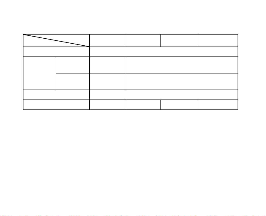
2. SPECIFICATIONS........................................................................................................2
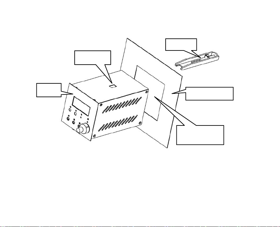
3. DIMENSIONS & INSTALLATION............................................................................ 4
3.1 MT-52 Dimensions & Installation................................................................... 4
3.2 MT-52-2J/3J/4J Dimensions............................................................................ 7
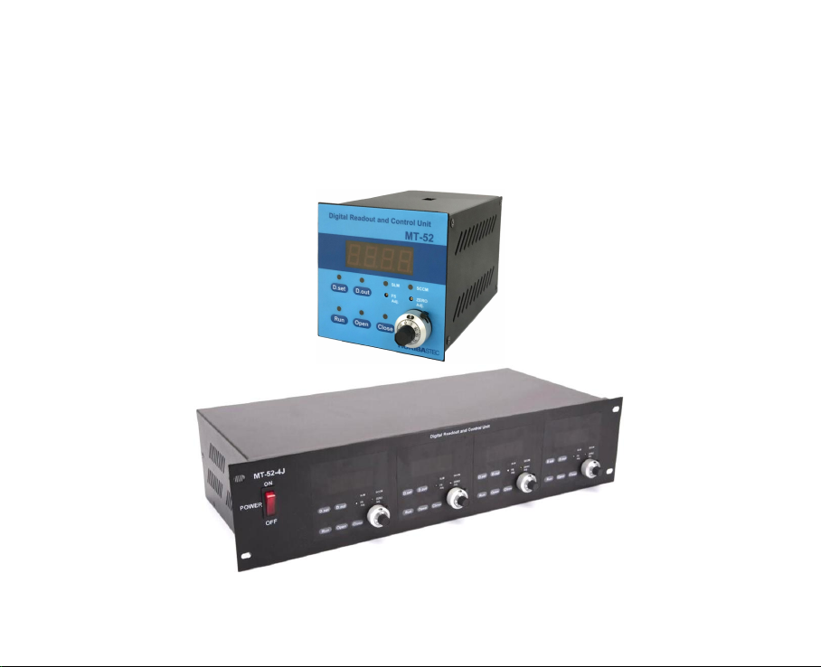
4. PANEL INTRODUCTION......................................................................................... 12
4.1 Front Panel View............................................................................................12
4.2 Rear Panel View.............................................................................................13
5. ELECTRICAL INTERFACE......................................................................................14
5.1 MFC Interface (D-sub 15/Female).................................................................14
5.2 COMM Interface (D-sub 9/Female).............................................................. 15
5.3 SIGNAL Interface..........................................................................................18
6. OPERATING INSTRUCTIONS.................................................................................19
6.1 Power On and Power Off............................................................................... 19
6.2 Basic Operations............................................................................................ 19
6.3 Instrument Configuration...............................................................................22

6.4 External Zero Adjustment.............................................................................. 26
7. FACTORY DEFAULT SETTINGS............................................................................ 27
8. ATTENTIONS.............................................................................................................28
9. ORDERING GUIDE...................................................................................................29
APPENDIX Ⅰ: RoHS.......................................................................................................30

1
1. INTRODUCTION
MT-52 series flow display instruments can supply power, realize control operation,
flow setting and flow display function for mass flow controller (MFC) or mass flow
meter (MFM).

2
2. SPECIFICATIONS
Table 2-1. MT-52 Series Specifications
ITEMS MODELS
MT-52
MT-52-2J
MT-52-3J
MT-52-4J
AC Power Supply
185~240VAC 50/60Hz
Input Power Max.
19.8W
39.6W
59.4W
79.2W
Channel Numbers
1
2
3
4
DC Power
Output
+15V ± 5%
-15V ± 5%
Imax=150mA
Imax=350mA
Imax=300mA
Imax=700mA
Imax=450mA
Imax=1050mA
Imax=600mA
Imax=1400mA
SET Output Type
0~5V(Default), or 1~5V, or 4~20mA
SET Output Accuracy
±0.2% (@ F.S.=1000, 5~40℃)
Signal Input Type
0~5V(Default), or 1~5V, or 4~20mA
Display Digits
Display Accuracy
F.S. ± 2 digits (@ F.S.=1000, 5~40℃)
MFC Interface
D-sub 15/Female
External Control Interface
D-sub 9/Female
digits
2
1
/3

3
Continue to Table 2-1. MT-52 Series Specifications
ITEMS MODELS
MT-52
MT-52-2J
MT-52-3J
MT-52-4J
Operating Temperature
0~50℃
Dimensions
(mm)
Panel
(L×H)
96×96
483×110
Body
(L×W×H)
90×156×90
440×201×109
Warm-up Time (min)
5
Weight (Kg)
0.9
3.4
3.7
4.0

4
3. DIMENSIONS & INSTALLATION
3.1 MT-52 Dimensions & Installation
3.1.1 Dimensions
Figure 3.1-1. MT-52 Exterior

5
Figure 3.1-2. MT-52 Dimensions (unit: mm)

6
3.1.2 Installation
Figure 3.1-3. MT-52 Installation
Before Installation, fasteners are assembled as shown above. Then the MT-52 is
inserted into the mounting hole of the mounting plate, and finally the fasteners are
loaded into the fixing hole, and the screw should be tightened. The fasteners are a set of
two, and the other one on the bottom is installed as mentioned above.
Mounting Hole:
91×91mm
Mounting plate
Fastener
MT-52
Fixing hole

7
3.2 MT-52-2J/3J/4J Dimensions
Figure 3.2-1. MT-52-4J Exterior

8
Figure 3.2-2. MT-52-2J Dimensions (unit: mm)

9
Figure 3.2-3. MT-52-3J Dimensions (unit: mm)

10
Figure 3.2-4. MT-52-4J Dimensions (unit: mm)

11
Figure 3.2-5. MT-52-2J/3J/4J Dimensions (left elevation) (unit: mm)
Note: The right elevation and the left elevation are mirror image.

12
4. PANEL INTRODUCTION
The panels and interfaces of MT-52 series flow display instruments are the same,
take MT-52 as an example for explanation.
4.1 Front Panel View
1) Display window
2) “D.set” key & light (white)
3) “D.out” key & light (white)
4) “SLM” light (white)
5) “SCCM” light (white)
6) “Display F.S.” trimmer potentiometer
7) External “Zero Adj.” potentiometer①
8) “Run” key & light (green)
9) “Open” key & light (yellow)
10) “Close” key & light (yellow)
11) “SET” knob
(1)
(2)
(3)
(4)
(5)
(6)
(7)
(8)
(9)
(10)
(11)
Note: 1. The “Zero Adj. potentiometer” is used for external zero adjustment of MFC or
MFM. It only works for MFC or MFM with this function. Please refer to MFC or
MFM instructions for details.

13
4.2 Rear Panel View
①
②
③
④
⑤
⑥
⑦
Table 4.2-1. Rear Panel Introduction
No.
Items
Details
①
AC_IN
AC220V input interface (for the sake of safety, "earth”
must be connected to the earth)
②
COMM
External control input/output interface
③
INT / EXT①
Internal/external control change switch
④
MFC
MFC or MFM connection interface
⑤
SIGNAL
Flow signal measurement interface (only for voltage type)
⑥
SW1
Display F.S. change switch
⑦
SW2
Configuration switch
Note: 1. "INT" means “internal control” and "EXT" means “external control”.

14
5. ELECTRICAL INTERFACE
5.1 MFC Interface (D-sub 15/Female)
Table 5.1-1. Pin Assignment of MFC Interface
Pin
Details
Pin
Details
1
External Zero Adj.①
8
Chassis Ground
2
Not Connected
9 & 10
Not Connected
3
Signal Common
11
-15VDC Power Supply
4
SET Output
12
-15VDC Power Supply
5
Valve Override
13
Not Connected
6
Signal Common
14
Power Common
7
Flow Signal Input
15
+15VDC Power Supply
Note: 1. The pin is used for external zero adjustment of the MFC or MFM. For details,
please refer to chapter “6.4 External Zero Adjustment”.
2. Pin 3 and pin 6 are short connected internally, and connected with pin 14.
Pin 11 and pin 12 are short connected internally.

15
5.2 COMM Interface (D-sub 9/Female)
Table 5.2-1. Pin Assignment of COMM Interface
Pin
Details
1
Flow Signal Output (same as pin 7 of MFC interface )
2
+15VDC (only for external valve override, not for power supply)
3
+5.00V Reference Voltage
4
Signal Common
5
External SET Input
6
External Valve Override Input
7
-15VDC (only for external valve override, not for power supply)
8
Internal Valve Override Output
9
Internal SET Output

16
The “COMM interface” is an external controlling signals input/output interface.
There are 3 external control methods that can be selected according to the actual
situation as follows.
First, you must turn the "INT / EXT" switch on the rear panel to "EXT" , which
means "External Control".
1. Simultaneous use of external “SET” and external “valve override”
(1) Connect the external “SET” signal (its type must match the nominal type of the
instrument) to pin 5 ;
(2) Connect the external “valve override” signal to pin 6 ;
(3) Connect the ground signal of the external signals to pin 4.
Note: In this mode, the MFC connected to the instrument is controlled by the external
“SET” and external “valve override” signals. The “SET knob” and “Run”, “Open”,
“Close” keys on the front panel of the instrument are not available.
2. Use only external “SET” without external “valve override”
(1) Connect the external “SET” signal (its type must match the nominal type of the
instrument) to pin 5 ;
(2) Connect pin 6 (external “valve override” signal) to pin 8 (internal “valve override”
signal) ;

17
(3) Connect the ground signal of the external signals to pin 4.
Note: In this mode, the MFC which connected the instrument is controlled by the external
“SET” signal. The “SET knob” on the front panel is not available. But the “Run”,
“Open”, “Close” keys are still available.
3. Use only external “valve override”, without external “SET”
(1) Connect the external “valve override” signal to pin 6 ;
(2) Connect pin 5 (external “SET” signal) to pin 9 (internal “SET” signal) ;
(3) Connect the ground signal of the external signals to pin 4.
Note: In this mode, the MFC connected to the instrument is controlled by the external
“valve override” signal. The “Run”, “Open”, “Close” keys on the front panel are not
available. But the “SET knob” is still available.
This manual suits for next models
4
Table of contents
Popular Control Unit manuals by other brands

WAGNER
WAGNER EPG-SPRINT XE Translation of the original operating manual

ORTEA NEXT
ORTEA NEXT ICAR WEB ETH instructions

Conel
Conel CLEAR FILL installation instructions

Chattanooga
Chattanooga Intelect Advanced 2766 user manual

Texas Instruments
Texas Instruments INA260 user guide

Pepperl+Fuchs
Pepperl+Fuchs PXV Series quick start guide

Toshiba
Toshiba nv Series user manual

oventrop
oventrop Multiblock T Installation and operating instructions for the specialised installer

Spirax Sarco
Spirax Sarco 25P Installation and maintenance instructions

Still
Still Easy Control Original instructions

Siemens
Siemens PSO 4000 Quick reference guide

Lenze
Lenze ECS series operating instructions