Horizon Fitness FCJJ-24 User manual

1
Horizon Fuel Cell Software Adaptor
User Manual
FCJJ-24

2
Contents
1. Introduction
2. Intended Use
3. General Safety Precautions
4. Related Issues
5. Hardware Installation
6. Software Installation
7. Learning to Use the Graphic Software
8. Data Acquisition Board
9. Power Sources and Loads
10. Measuring Resistance
11. Basic Knowledge of Wind Power Technology
12. The Differences between a 3-Phase Motor Generator
and a DC Motor Generator
13. The Experiments
14. Fault Diagnostics
15. Technical Data
Horizon Fuel Cell Technologies (Shanghai) Co.Ltd.
4th Floor, Block 18,
No.271 Qiangyang RD.
Shanghai 200333, P.R.China
Phone +86 21 52709082
Fax +86 21 52705064
e-mail [email protected]
website www.horizonfuelcell.com

3
1. Introduction
Diminishing resources, more severe environmental impacts and the ever- increasing demand for energy
force us to re-evaluate the structure of our energy supply system. Automobile and oil companies
increasingly invest in hydrogen technology because it offers solutions to some of these concerns. This
fascinating technology combines a sound energy supply with minimal impact on our natural resources.
In order to learn more about how hydrogen fuel cells can power everything from cell phones to cars, the
Fuel Cell Software Adapter allows you to directly peer into the electrical operation of a fuel cell in order to
observe how it produces hydrogen from plain water and then uses this hydrogen to create electricity.
The Fuel Cell Software Adapter takes your regular desktop or laptop PC and turns it into a laboratory
instrument where you can “graphically” observe the electrical relationships among voltage, current,
resistance and power. Meters are fine for static electrical measurements, but when it comes to seeing what
happens in real time – all at once - nothing beats a graphic display!
This is what you have in the Fuel Cell Software Adapter – a laboratory instrument that is specifically
designed to test fuel cells. And the following experiments will teach you more in one minute than you can
experience in hours of tedious laboratory measurements with a meter. A picture is worth a 1000 words and
nothing is more appropriate for this comparison.
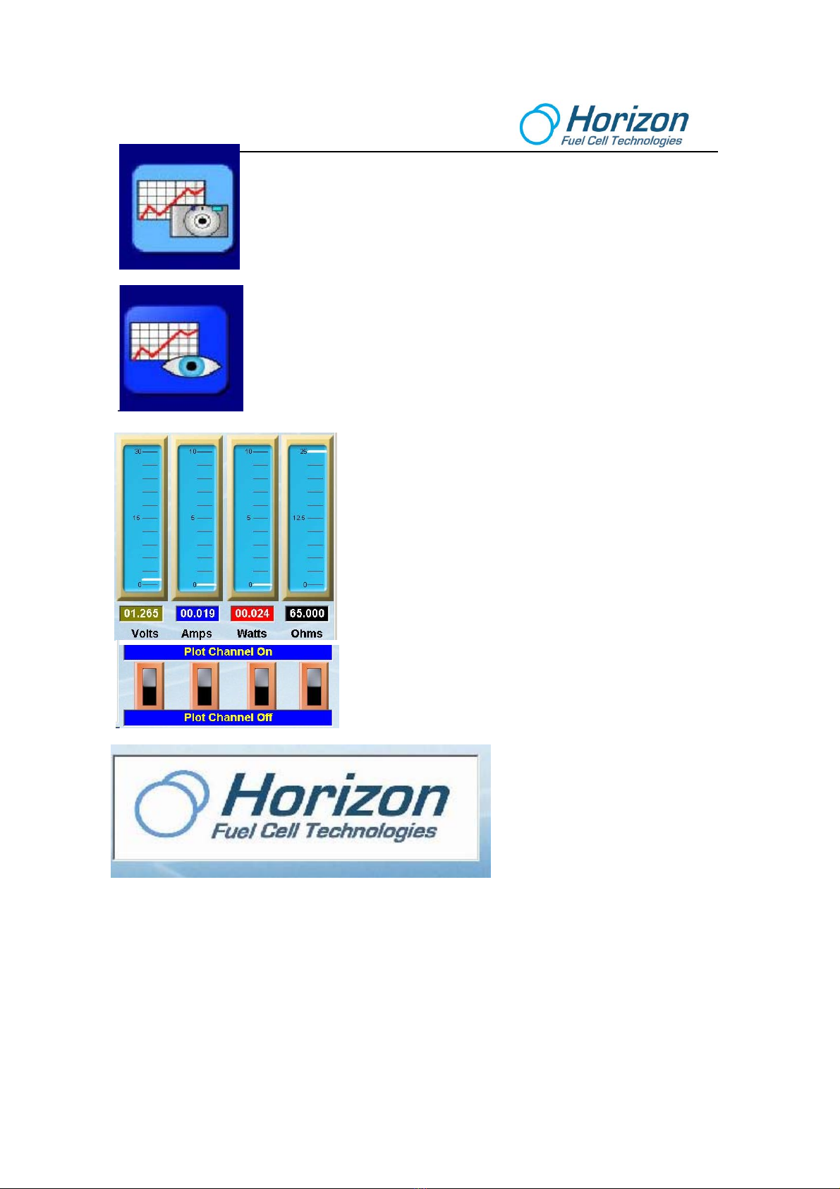
The Fuel Cell Software Adaptor provides a facility for automatically recording and evaluating the voltage,
current and power values of fuel cells. It includes PC software for recording measurements, as well as a
Data Acquisition Card for connecting to a computer's USB interface.
Horizon’s Fuel Cell Software Adaptor has been especially developed for fuel cells in the lower power
range. The PC software and the Data Acquisition Card are designed for measuring and recording voltage,
current, load resistance and power values for fuel cells with a power capacity of up to 5 watts.
The following measurement ranges are possible:
•Voltage measuring range:
0 volts to 5 volts
•Current measuring range:
0 amps to 1 amp
•Power measuring range:
0 watts to 5 watts
•Resistance measuring range:
0 ohms to 99.999 ohms
For best results, please review each experiment before performing it. This will avoid misunderstandings and
provide you with knowledge of what is about to happen.
We wish you many enjoyable hours learning about fuel cell technology and how it can benefit our world with
the Fuel Cell Software Adaptor.

4
2. Intended Use
•Measurements can be carried out and evaluated on fuel cells in the power range up to 5 watts with
the Fuel Cell Software Adaptor’s external Data Acquisition Card and the associated software.
•The hardware and software were developed exclusively for educational teaching and
demonstration purposes. Any other use is prohibited!
3. General Safety Precautions
In order to avoid any risks, you must follow the following General Safety Precautions when carrying out
measurements with the Fuel Cell Software Adaptor and fuel cells.
•The system may only be set up and operated by a competent person. Students require adult
supervision at all times.
•Read the Operating Instructions before setting up the system. Follow them during use and keep
them readily available for reference. This also applies to the Operating Instructions for the fuel cells
and, if appropriate, any electrolyzer used in the experiments.
•The system is not a toy. Operate the equipment and keep it and the gases produced out of the
reach of small children.
•Unless specified otherwise, do not short-circuit or reverse the polarity of the terminals.
•Remove inflammable gases, vapors and fluids from the vicinity of fuel cells and electrolyzers. The
catalysts contained in the system can trigger spontaneous combustion.
•Hydrogen and oxygen may escape from fuel cells and electrolyzers. To prevent the gases
collecting and forming explosive mixtures only use the system in well ventilated rooms.
•Fuel cells and electrolyzers may only be operated where there is sufficient ventilation at all times.
The operator is obliged to prove this by means of appropriate measurements.
•Remove from the vicinity of fuel cells and electrolyzers anything that could ignite the hydrogen such
as a naked flame, materials that can become charged with static electricity, substances with a
catalytic action, etc.
•Remove from the vicinity of fuel cells and electrolyzers all substances that could spontaneously
ignite with increased oxygen concentration.
•Do not smoke in the vicinity of fuel cells and electrolyzers.
•Only use the gas storage tanks Horizon provides to store gas. Never connect other alternatives.
•Horizon will not accept any responsibility for injuries or damage sustained in the event of these
Safety Precautions not being followed

5
4. Related Issues
4.1 Reverse Engineering
You are not entitled to reverse engineer, decompile or disassemble the software product in whole or in part.
4.2 Errors and Omissions
Horizon has made every effort to supply the software and hardware without errors; however, we are not
responsible for any unintentional errors or omissions in the design, construction or operation of the product.
If you should notice undiscovered errors, please contact us.
Horizon Fuel Cell Technologies
www.horizonfuelcell.com
4.3 System Requirements
The following operating systems are supported - Windows 2000, Windows 98, Windows ME, Windows NT,
Windows XP, Windows Vista. MACs with INTEL processors can use Parallels “Desktop 3.0 for Mac”.
4.4 Minimum Computer Requirements
The minimum requirements are the same as those of the respective operating systems. In addition, the
Microsoft .NET Framework run-time environment is required for running the Fuel Cell Software Adapter,
which can be found on the installation CD in German and English.
4.5 Software Installation
You will need administrator rights for software installation under Windows 2000, Windows NT, Windows XP
or Windows Vista.
4.6 Supplied Materials
•Data Acquisition Card
•USB Cable
•One 1 ohm, two 10 ohm resistors.
•Capacitor
•CD-ROM with FCA graphics software, USB Driver Software, user manual and PDF installer
•Connection cables

6
4.7 Other Required Materials Not Supplied
•Windows PC – MACs must have Parallels “Desktop 3.0 for Mac”
•Fuel cell
•Solar panel
•Table fan for wind turbine
•Small DC motor and propeller
•Battery Holder (two AA batteries not included)
•Wind Turbine
5. Hardware Installation
1. Connect one end of the USB cable to the computer and the other end to the Data Acquisition Card.
2. The green and blue LEDs on the Data Acquisition Card should flash to indicate that the connection
is made and power from the computer is applied to the circuit board.
6. Software Installation
1. Insert the Horizon Fuel Cell Software Adaptor CD-ROM into your computer’s disc drive and close
the door.
2. On the Desktop, right-click on “Start” then click “Explore”. Find your CD-ROM drive (D, E or higher)
then click it to bring up the folder’s contents.
3. Double click on the USB driver software (USB Driver Installer.exe) to install it.
4. Double-click on the Horizon FC Installer file and follow the instructions to install it.
5. Next, minimize all applications until the Desktop reappears again. A Horizon FCA
icon like that shown here should appear:
6. Click the Horizon FCA icon. You can choose either English or German.
7. You have successfully installed the hardware and software. Now proceed to
Section 7 on “Learning to Use the Graphics Software” to understand what to do next.

7
7. Learning to Use the Graphic Software
The PC graphic software screen is divided into several regions that control how electrical quantities such as
voltage, current, power and resistance readings are displayed.
The large grid area continuously displays four plotted lines in four colors. The colors match the voltage,
current, power and resistance values below the vertical meters.
•Green – Voltage in volts
•Blue – Current in amperes
•Red – Power in watts
•Black – Resistance in ohms

8
Before any plots can occur, the graphic software must connect with the attached
circuit board that is transmitting data. To do so, first select the correct Comm port
number then click on the Connect icon. You can type over the number displayed if it
is not correct. To find the correct Comm port go to Control Panel --> System -->
Hardware Manager --> Device Manager then click on the Comm port. This is the
correct Comm port to type into the number area. Then click the connector icon –
the one with the red x.
If correct, the Connect icon will show that the connection is made. If the Comm port
is not correct an error message will be displayed, which is usually due to a Comm
port already in use.
The plot area can be zoomed in and out of a time range (horizontal axis) or a
voltage, current, power or resistance range (vertical axis).
The up and down arrows will zoom the plot in a vertical direction. Up to
increase and down to decrease.
The left and right arrows will zoom the plot in a horizontal direction - left for
more time and right for less time.
Click the center double-arrow icon to clear the screen and reset the plot. If
the plot does not immediately start, click the double-arrow icon again.
To begin data logging, click the data log icon. A file will automatically open to record
the data being sent by the circuit board.
To view the logged data, click on this icon. The logged data will be displayed over
the plot area where it can be examined. This same file can be ported to a spread
sheet program like Excel for further analysis and plotting. To find the path to the
logged data go to Program Files ÆHorizon FCA ÆData on your hard disk.
Click this icon to close the data log file and erase all logged data.

9
Click this icon to capture the plot image on the screen.
These images are automatically saved to a file with a unique name and can be
extracted and included in reports or printed out. To find the path to these images go
to Program Files ÆHorizon FCA ÆData on your hard disk. You will find the
captured screen shots as .jpg files, which you can extract and use in reports or print
out directly. You can also rename the files, as well.
Click this icon to view the captured images.
The four meters display the voltage, current, power and resistance.
Their scales are fixed and unlike the grid plot area, cannot be
changed.
The resistance reading of 99.999 ohms is maximum even if the
actual resistance is more.
The other electrical measurements are consistent with their actual
values.
To reduce screen clutter in the plot area, the individual switches
can be clicked to turn ON or turn OFF the selected plot line.
If your computer is connected to the
Internet, clicking on the Horizon icon
will take you to their website.

10
8. Data Acquisition Board
The Data Acquisition Board is the electronic interface between devices such as a fuel cell, solar
panel and wind turbine. When connected to a computer via a USB cable, it measures and
computes voltage, current, resistance and power then transmits these electrical quantities 3 times
a second to the computer. The computer software displays these quantities as both numbers and
colored line plots as they are transmitted.
Input and Output Connectors
There are two (2) Input connectors. One is colored red, which indicates positive or plus (+)
polarity and the other is colored black to indicate negative (–) polarity. In the following
experiments, power sources such as a battery, solar panel, wind turbine or fuel cell will be
connected to the Input connectors.
There are four (4) Output connectors, but they are actually two sets of positive and negative
connectors arranged in parallel - meaning that the two positive (red) terminals are connected
together and the two negative (black) terminals are connected together (but not to each other; i.e.,
positive to positive and negative to negative). In the following experiments loads such as a
resistor, capacitor, motor and fuel cell are used. (a fuel cell can be both a power source as well as
a load).
The diagram in the next subject line shows how these connectors are arranged.
1 Ohm Sense Resistor
A 1 ohm sense resistor (labeled R4 on the circuit board) is connected between the Input and
Output connectors. Its main purpose is to measure the current flow from the power source on the
Input connectors going into the load on the Output connectors. The sense resistor, R4, is also
attached to the microprocessor (U1), which does the work of “sensing” current and load
resistance.
Since the loads in the following experiments tend to be of small resistance values, generally 10
ohms, or less, the 1 ohm sense resistor must be considered in current and resistance calculations
(as will be shown later). An equivalent circuit is shown on the following page:

11
Flashing LEDs
The two flashing LEDs represent the relative strength of the voltage and current being measured.
The green LED indicates voltage and the blue LED indicates current - - the brighter the LEDs, the
greater the relative voltage and current being measured (and visa versa). To enhance the
understanding between the circuit board and the computer display software, these are the same
colors used on the computer display software to display voltage and current.
USB Connector
The USB connector is the cube-like part on the left side of the circuit board. When a USB cable
is attached to it and to a computer, power for the circuit board is delivered from the computer and
data is transmitted by the circuit board to the computer for display and analysis.

12
9. Power Sources and Loads
The experiments use the following power sources and loads.
Power Sources
•Battery
•Solar Panel
•Wind Turbine
•Fuel Cell
Loads
•Resistors
•Capacitor
•Motor – Propeller
•Fuel Cell (a fuel cell can be both a power source and a load)
What is a Power Source?
For these experiments a power source is a device that produces both electrical voltage and
current (in effect, power). The power sources use chemical energy (battery, solar panel),
magnetic energy (wind turbine) or hydrogen (fuel cell) to generate voltage and current.
The equation for power is shown below:
P = E*I
Where P = Power in watts
E = Voltage in volts
I = Current in amps
What is a Load?
A load is a device that accepts the power coming from a power source and (may) use the power
to do work, like spin a motor. Other loads like resistors and capacitors serve to dissipate or store
power (respectively). In all cases, loads are used to both consume and regulate the power being
produced.
Generally speaking, a load is measured as resistance whose units are in ohms.
In relative terms, a “light” load has a “large” resistance and a “heavy” load has a “small”
resistance. This may be counter intuitive, but it is the case, nevertheless. For example, a 100
ohm resistor presents a “lighter” load to a circuit as compared with a 10 ohm resistor.
The equation for computing the association among voltage, current and resistance (load) is as
follows:
E = I*R
Where E = Voltage in volts
I = Current in amps
R = Resistance in ohms

13
What is a Resistor?
A resistor is an electrical device (usually composed of a passive material like carbon) that limits
the flow of current and voltage from a power source. Resistors are important components in any
electrical circuit, since other components that are connected to the resistors depend on the
limited current and voltage they produce to operate correctly.
The physical part and electrical symbol for a resistor are shown below:
What is a Capacitor?
A capacitor is a device that stores energy from a power source and then releases the stored
energy when it is no longer available. It is somewhat like a rechargeable battery, but quite
different in terms of its construction and use in circuits. Depending on the size of the capacitor
(its value, in units called Farads), it can store and release energy many times faster as compared
with a battery. The experiments will use the capacitor to “filter” or smooth out the voltage “ripples”
produced by the wind turbine.
Capacitors come in two basic types – polarized and non-polarized. A polarized capacitor requires
that you connect the positive lead to the red terminal on the circuit board and the negative lead to
the black terminal. Non-polarized capacitors can have either lead connected to positive or
negative. The experiments only use a polarized capacitor.
The physical part and electrical symbol for a polarized capacitor are shown below:
The longer lead of a polarized capacitor is positive (+) while the shorter lead is negative (-). The
negative lead is also identified by a series of bar-and-arrow symbols on the part itself. In the
experiments that follow, be sure to observe the positive and negative portions of the capacitor.

14
What is a Battery?
A battery stores chemical energy, which can be converted into electrical energy.
The physical part and electrical symbol for a battery are shown below:
Primary batteries are ready to produce current as soon as they are manufactured. Primary
batteries are generally used in flashlights and must be replaced when they go “dead”.
Secondary batteries can be recharged by applying an electrical current, which reverses the
chemical reactions that occur during its use. All car batteries are secondary batteries that need
constant recharging by the car’s alternator.
The capacity of a battery depends on the discharge conditions, such as the magnitude of the
current and the duration of the current. The Battery Capacity (AH, Ampere Hour) is defined as
the maximum constant current that a fully charged battery can supply for 20 hours at 68°F (20°C)
down to a predetermined terminal voltage. Thus a 1000mAH (milliamp hour) battery will deliver
50mA over a period of 20 hours at room temperature. However, if it is discharged at 100mA, it will
run out of charge within 10 hours.

15
What is a Motor?
There are many types of electrical motors, but the one used in the experiments is a small DC
motor that attaches to a propeller. Normally constructed with spinning magnets (rotor) that
surround a coil of wires (stator), a motor converts electrical energy into mechanical energy by
taking in electrical power and then spinning a shaft using magnetic energy. The shaft can be
connected to a “load” such as a propeller to do work; i.e., spinning the propeller to generate wind
energy.
The physical part and electrical symbol for a DC motor are shown below:
What is Electrolysis?
For our purposes the term electrolysis defines splitting water into its two main components –
hydrogen and oxygen. This is what a “reversible” fuel cell does; it splits water (H2O) into
hydrogen and oxygen gases in electrolysis mode and then recombines hydrogen and oxygen in
fuel cell mode to create electricity, which is why it is called “reversible”. It doesn’t take much
voltage (about 1.5 volts) to split water into hydrogen and oxygen as one of the experiments will
demonstrate.
The physical part and symbol for a reversible fuel cell are shown below:
O H
MEA

16
10. Measuring Resistance
When measuring resistance both the external load resistor as well as the 1 ohm sense resistor
built into the circuit board must be taken into consideration.
Example 1:
The illustration below shows a 10 ohm load resistor placed across one set of the OUTPUT
terminals. The total resistance is really 11 ohms (10 ohm load resistance + 1 ohm sense
resistance). While the fuel cell is shown as the power source, a battery, solar panel or wind
turbine can also be substituted.
The equivalent circuit is shown below:
Microprocessor
1 ohm
sense
resistor
INPUT
OUTPUT
USB
Connector
+5V
GND
Voltage
LED
Current
LED O H
ME
A
10 ohm
Load
resistor
1 ohm
sense
resistor
10 ohm
Load
resistor
= 11 ohms total

17
Example 2:
The illustration below shows two 10 ohm load resistors, in parallel, placed across both sets of the
OUTPUT terminals. The total resistance is really 6 ohms (5 ohm “parallel” load resistance + 1
ohm sense resistance). While the fuel cell is shown as the power source, a battery, solar panel
or wind turbine can also be substituted.
The equivalent circuit is shown below:
Microprocessor
1 ohm
sense
resistor
INPUT
OUTPUT
USB
Connector
+5V
GND
Voltage
LED
Current
LED O H
ME
A
10 ohm
Load
resistor
10 ohm
Load
resistor
1 ohm
sense
resistor
10 ohm
Load
resistor
= 6 ohms total
10 ohm
Load
resistor
R1 R2
Rparallel =
R1 x R2
R1 + R2
=5ohms

18
11. Basic Knowledge of Wind Power Technology
You should notice that the power is proportional to the cube of the wind speed and the square of
the radius of the rotor blades. If the radius of the rotor blades is doubled, the swept area is
quadrupled.
If the wind speed is reduced by half (1/2), the power is reduced to 1/8 of the original power. Thus,
a light wind contains little power, so remember to use a larger table fan for the experiments. It will
produce much better results.
Albert Betz was a German Physicist and a pioneer of wind turbine technology. Betz found out that
we can only harvest, at maximum, 16/27 or 0.593 of the power from the wind. This number is
called the Betz coefficient and is the theoretical maximum efficiency that a wind turbine can
harvest from the wind.
In real world, we have to take into account many other factors that affect the wind power being
converted into electrical power by the wind turbines. The efficiency of wind turbines is affected by
the blade parameters, generator efficiency and the mechanical losses in the gear box, etc. But
there is ample wind to make clean, renewable energy for decades to come.
A wind turbine is a device that uses rotor blades
connected by a mechanical shaft to an electrical
alternator to generate electricity. When the wind blows
across the rotor blades, the propeller shaft rotates the
alternator and the alternator makes electricity (much the
same when your car’s engine spins the alternator to
charge the car’s battery).
The amount of power that is produced by a wind turbine
depends on many factors – one of which is the rotor
blades. The power that can be harvested in the area
swept by the wind turbine rotor blades can be described
as follows:
P = 0.5*ρ*A*V³
Where:
P = Power in Watts
ρ= Air Density in Kg/m³ (about 1.225Kg/m at sea level,
less higher up)
A = Rotor Swept Area in m² = πr² (r= radius of the rotor)
V = Wind Speed in m/s

19
12. The Differences between a 3-Phase Motor Generator
and a DC Motor Generator
The wind turbine used in the following experiments uses a 3-phase motor generator, also called
an alternator that is much more efficient at producing electrical power as compared with a
conventional DC motor. The following will point out these differences.
The main difference between a DC motor and a 3-phase motor is the number of coil windings
inside the motor. A DC motor has 1 coil winding whereas a 3-phase motor has 3 coil windings.
The rotor of a DC motor consists of a coil wound around it, but not touching it. This coil is
connected to the motor terminals with a brush type commutator. The function of the commutator
is to switch the polarity of the coil as the rotor rotates every half cycle.
Since the brushes are in contact with the rotating rotor, they will
eventually wear out.
The rectified output of a DC motor generator outputs 2 half cycle positive waveforms as shown
here. Notice that the power drops to zero on every half cycle, which makes DC motors (like the
ones Thomas Edison developed) very inefficient and unreliable.
In contrast to a simple DC motor, there are 3 coils wound on the
stator of the 3-phase motor and they are spaced 120 degrees apart.
There is no commutator in the motor. The three rectified phases and
rectified DC output waveforms are shown below:

20
The important concept to realize is that since the 3 coils are spaced equally apart, each of them
reaches its instantaneous peak at different times. When the individual phases are combined by
rectifiers, the voltage and, thus the power never goes to zero like in a DC motor.
The 6 half cycles overlap each other at every 1/6 of a rotation (every 60 degrees). The effect of
these 6 half cycles per rotation delivers more constant power to the load than that of the 2 half
cycles per rotation from a DC motor.
Thus a 3-phase motor generator delivers more output than a DC motor generator. Since a 3-
phase motor generator does not have a commutator, its usable life is also much longer than that
of a DC motor generator.
The tradeoff is that a 3-phase motor consists of more materials like copper windings. However,
not having to worry about replacing commutator brushes makes up for the extra amount of
materials. Nicola Tesla, a student of Thomas Edison, developed the 3-phase AC motor and
revolutionized electricity as we know it today. All industrial motors are 3-phase.
Table of contents
Other Horizon Fitness Receiver manuals
Popular Receiver manuals by other brands

Itowa
Itowa IT3R22 user manual

Hallicrafters
Hallicrafters Skyrider Defiant SX24 Operating/service instructions

Realistic
Realistic Pocket-Scan Pro-22 owner's manual

Planet Audio
Planet Audio PM40RGB user manual

Lippert Components
Lippert Components Touch Audio VD300WR owner's manual

Pioneer
Pioneer XV-DV303 Setting up