Horizon Fitness FC-11 User manual

I
TRIMMER
FC-11
010322/FC11/02E/DV UM201033-02
Important Information
- This manual is designed to help you to install, operate and maintain Trimming System
FC-11. Read, understand and keep this manual in a safe and convenient place.
- Do not operate FC-11 until you read and understand the instructions in this manual.
- Horizon International Inc. shall not be liable for incidental consequential damages result-
ing from : improper or inadequate maintenance by customer; unauthorized modification or
misuse; operation outside of the environmental specifications for the product.
- Horizon International Inc. pursues a policy of continuing improvement in design and
performance of the product. Therefore, the product design and specifications are subject to
change without prior notice and without our legal obligation.
- All rights are reserved. No part of the manual may be photocopied, reproduced or trans-
lated to another language without the prior written consent of Horizon International Inc.

II
Safety Precautions
- The signal word WARNING indicates a potentiall hazardous situation which, if not
avoided, could result in death or serious injur .
- The signal word CAUTION indicates a potentiall hazardous situation which, if not
avoided, ma result in damage on machines. It ma also be used to alert against unsafe
practices.
- Read and understand all safet instructions with signal word such as WARNING and
CAUTION. If safet instructions are ignored, personal injur ma result.
- Horizon International Inc. cannot anticipate ever possible situation that might involve
a potential hazard. The instructions in this manual and warning labels on the machine are
therefore not all inclusive.
- All equipment shall be locked out or tagged out to protect against accidental or inad-
vertent operation when such operation could cause injur to personnel. Do not attempt to
operate an switch, valve, or other energ isolating device where it is locked or tagged out.
- Do not operate the machines when an covers are removed.
- Some of the drawings in this manual show the machine uncovered for explaining the
detail or inside of machine.

III
CONTENTS
Important Information ............................................................................................I
Safety Precautions....................................................................................................II
1. Before You Begin
1-1 Specifications......................................................................................................2
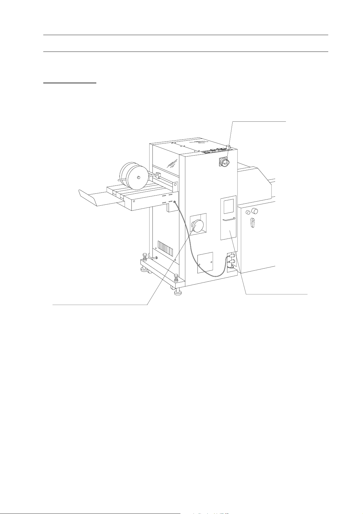
1-2 Mac ine Descriptions ........................................................................................3
1-2-1 Machine Descriptions and Functions..............................................................3
[1] General View...................................................................................................3
[2] Press Section ...................................................................................................4
[3] In-Feed Section ...............................................................................................5
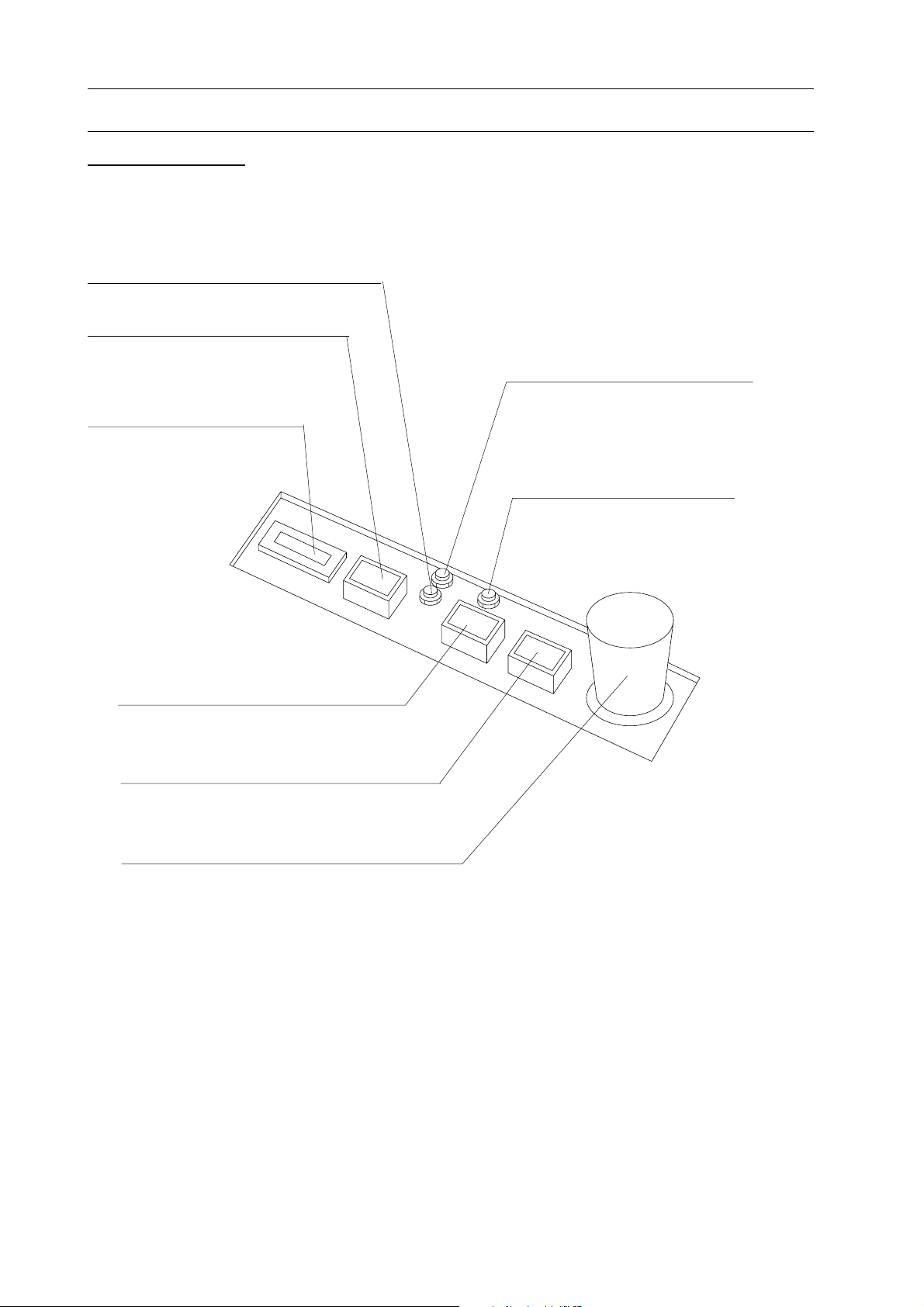
[4] Operation Panel ...............................................................................................6
1-3 Accessories/Option.............................................................................................7
2. Set Up and Operation
2-1 Operation Procedures .......................................................................................10
3. Maintenance Hints
3-1 Replacing Upper and Lower Knife ..................................................................12
3-1-1 Upper Knife Replacement ..............................................................................12
3-1-2 Lower Knife Replacement..............................................................................12
4. Installation Instructions
4-1 Installation Instructions ....................................................................................14

IV

1
1. Before You Begin
1. Before You Begin
1-1 Specifications ........................................................................................... 2
1-2 Machine Descriptions.............................................................................. 3
1-3 Accessories/Option .................................................................................. 7

2
1. Before You Begin
1-1 Specifications
Model FC-11
Cutting Dimensions Spine to fore edge : 99 to 225 mm (3.9" to 8.9")
Booklet Size 100 x 200 mm to 240 x 330 mm
(4.0" x 7.9" to 9.4" x 12.9")
Trimming Length 15 mm (0.6")
Cutting Thickness 44 sheets of 80 gsm stock
Production Speed 2600 booklets/hour
Voltage/Frequency 100 V 50/60 Hz, 5.8 A/5.1 A 120 V 60 Hz, 5.0 A
230 V 50 Hz, 3.4 A
Power Consumption 100 V 50Hz, 310 W 100 V 60 Hz, 350 W
120 V 60Hz, 320 W 230 V 50 Hz, 450 W
Weight 170 kg (375 lb)
Machine Dimensions 570(W) x 610(D) x 1040 (H) mm
(22.5" x 24.1" x 41.0")
The machine design and specifications are subject to change without any notice.
(Before Trim)

3
1. Before You Begin
1-2 Machine Descriptions
1-2-1 Machine Descriptions and Functions
1] General View
Dust Box
This section gathers
trimmed paper.
Manual Handwheel
When power is off, release
stopper pin then upper cutter
can be lowered with this
manual handwheel.
Power Switch

4
1. Before You Begin
1-2 Machine Descriptions
2] Press Section
Transport Guide
This guide prevents booklet curling up.
Air Blow Nozzle
Trimmed paper is blown into dust
box by compressed air blast so that
no paper scraps are scattered in
trimmer unit or in delivery ramp.
Breaker
This breaker will trip when
upper cutter unit is locked.
Jam Sensor
In case booklet is jammed
over this section, FC-11
stops automatically.
Adjust Knob Lock Lever
This lever must be fastened
after trimming length is
adjusted.
Upper Knife
Trimming Size Scale
This scale indicates required trim-
ming size.
Lower Knife
Trimming Length Adjust Knob
This knob is used to adjust required
trimming length.
Transport Belts
These belts transport a stitched
booklet into FC-11.

5
1. Before You Begin
1-2 Machine Descriptions
3] In-Feed Section
Delivery Belts
These belts deliver booklets
from FC-11 after trimming
operation performed. Height
of delivery belts is adjustable.
Ejecting Roller
Stopper
Position of this stopper
is adjustable with trim-
ming length adjust knob.
Ejecting Roller Adjuster
This adjuster is used to adjust
clearance between delivery
belt and ejecting roller.
Press Plate Height Adjust Nuts
These nuts are used to adjust press plate
height depending on book thickness.

6
1. Before You Begin
Motor ON Button
This button starts motor.
Motor OFF Button
This button stops motor.
Emergency Stop Button
1-2 Machine Descriptions
4] Operation Panel
Counter
This counter indicates total
number of trimming for
maintenance purpose.
Power Lamp
Single Cut Button
Whenever this button is pressed,
knife is actuated.
Motor ON Lamp
This lamp illuminates when
FC-11 is ready for cut.
Jam Lamp
This lamp illuminates when jam
occurs in FC-11.

7
1. Before You Begin
1-3 Accessories/Option
1. Upper Knife (M003273-01 1 pc
2. Lower Knife (M003272-01 1pc
3. Leveling Bolt (HB12-100 2 pc
4. Mount Base (M003025-01 3 pcs 9. Stopper for Loop Stitch (Option 1pc
8. Leveling Bolt 2 (6200-1005 1 pc
6. Ground Wire (GW-1 1 pc
5. Transport Guide (M003308-AS 1 pc
7. Hold Supporter (M003327-03 2 pcs

8
1. Before You Begin

9
2. Set Up and Operation
2-1 Operation Procedures ............................................................................. 10

10
2. Set Up and Operation
2-1 Operation Procedures
1. Turn trimming length adjust knob and
set stopper to required book size.
Red line indicates book size.
Fasten lock lever after set up.
NOTE
Remove transport guide when book size is
adjusted shorter than 17 cm ( .7").
2. Turn po er on and then depress motor
ON button.
3. Depress single cut button to set knife to
its home position.
4. Depress start button of collator and then
depress stop button after a set of sheets is
delivered to SPF-11. Make sure that
booklet is trimmed correctly.
5. Start collating.
NOTE
If main motor of FC-11 is not on, main
motor of SPF-11 can not be started even if
motor ON button of SPF-11 is depressed.
Trimming Length Adjust Knob
Adjust Knob Lock Lever Transport Guide

3. Maintenance Hints
11
3. Maintenance Hints
3-1 Upper and Lower Knife Replacement................................................... 12

3. Maintenance Hints
12
3-1 Upper and Lower Knife Replacement
Adjuster Bolt
Lower Knife
Lock Bolts
Adjuster Bolt
Air Blow
Nozzle
Lock Screw
Release Lever
Manual Handwheel
pper Knife
Lock Bolt
pper Knife
Lock Bolts
CAUTION
1. When replacing knife, be sure to
turn power switch off.
2. nife edge is very sharp so utmost
care should be taken when knife is
replaced and/or installed.
Replace upper and/or lower knives when
abnormal cutting noise is created or dull
cutting occurs.
1. Turn power switch off.
2. Loosen lock screw and turn air blow
nozzle to the arrow direction.
3. Hold upper knife with hand and remove
three cutter lock bolts and springs. Re-
move upper knife.
4. Attach upper knife in the reverse order
of removing.
1. Remove upper knife following the
procedure of "3-1-1 pper Knife Replace-
ment".
2. Hold lower knife with hand and remove
four knife lock bolts. Remove lower knife.
3. Attach new lower knife in the reverse
order of removing.
NOTE
- Make sure that newly installed knife edge is
exactly flush with bed. If not, adjust lower
knife level by use of adjuster bolts. Fasten
four lower knife lock bolts after adjusting.
4. Attach upper knife.
NOTE
Make sure that upper knife can be moved up
and down smoothly by pulling release lever
and turning manual handwheel.
3-1-1 Upper Knife Replacement
3-1-2 Lower Knife Replacement

13
4. Installation Instructions
4-1 Installation Instructions.......................................................................... 14

14
4. Installation Instructions
1. Connect connector of FC-11 to recep-
tacle of SPF-11.
2. Push FC-11 to SPF-11 until cushion
rubbers installed on lower FC-11 touches
SPF-11. Make sure front side of FC-11 is
snugly aligned with that of SPF-11.
3. nstall conveyor unit at delivery end of
FC-11 with hooks of FC-11 inserted in key
holes of conveyor .
4. Level FC-11 by using leveling bolts.
5. Connect ground wire to ground terminals
on SPF-11 frame and FC-11 frame.
4-1 Installation Instructions
Conveyor
Leveling Bolts
Conveyor Connector
FC-11 Connector
(SPF-11)
(FC-11)
Ground Terminal
Ground Wire
Table of contents
Other Horizon Fitness Trimmer manuals