Horst Contour CHCFE30 User manual

HORST WELDING
8082 Rd 129
Listowel, ON N4W 3G8
Canada
519-291-4162
1-866-567-4162
Fax 1-519-291-5388
www.horstwelding.com
!
Do not attempt to operate the equipment without thoroughly
reviewing this manual for safe and proper operation.
Rev 030420 HW00102.CHCFE Header Wagon Owner Manual.SIS.140120
Operator’s Manual
Keep this manual with the machine at all times
PRINTED IN CANADA
Header Wagon
CHCFE30, CHCFE36, CHCFE3627,
CHCFE45, CHCFE4527
!
CAUTION
Operational Hazard
Personal Protection Equipment
(PPE) is required when operating
or maintaining this machine.
SNL00001
!
CAUTION
Operational Hazard
Do not exceed travel speed
rating of the components:
Maximum 50 km/h (30 mph).
Obey SMV speed limits.
50
km/h
30
mile/h
MAXIMUM
IL00007

2
Introduction . . . . . . . . . . . . . . . . . . . . . . . . . . . . .3
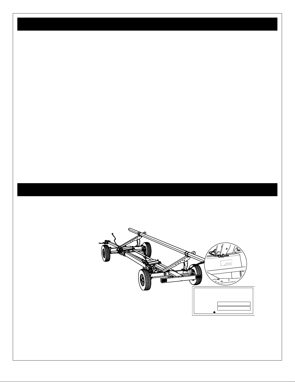
Serial Number Location . . . . . . . . . . . . . . . . . . .3
General Information . . . . . . . . . . . . . . . . . . . . . .4
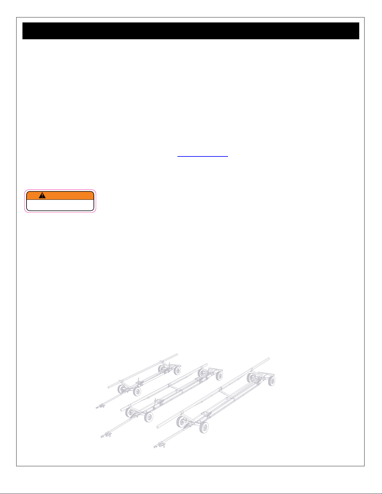
Intended Use . . . . . . . . . . . . . . . . . . . . . . . . . . . . . .4
Parts List . . . . . . . . . . . . . . . . . . . . . . . . . . . . . . . . .4
California Proposition 65 . . . . . . . . . . . . . . . . . . . . .4
. . . . . . . . . . . . .4
Safety . . . . . . . . . . . . . . . . . . . . . . . . . . . . . . . . . .5
. . . . . . . . .5
. . . . . . . . . . . . . . . . . . . . . . . . .6
Safety Guidelines. . . . . . . . . . . . . . . . . . . . . . . . . . .7
. . . . . . . . . . . . . . . . . . . . . . . . . . . . .7
Preparation. . . . . . . . . . . . . . . . . . . . . . . . . . . . . . . .8
Operation Safety . . . . . . . . . . . . . . . . . . . . . . . . . . .8
Storage Safety . . . . . . . . . . . . . . . . . . . . . . . . . . . . .8
Ratchet Strap Safety . . . . . . . . . . . . . . . . . . . . . . . .9
Maintenance Safety . . . . . . . . . . . . . . . . . . . . . . . . .9
. . . . . . . . . . . . . . . . . . . . . . . . . . .10
Brake Safety. . . . . . . . . . . . . . . . . . . . . . . . . . . . . .10
Safety Labels. . . . . . . . . . . . . . . . . . . . . . . . . . . 11
Safety Label Descriptions . . . . . . . . . . . . . . . . . . . 11
If labels need to be replaced:. . . . . . . . . . . . . . . . . 11
Safety Label Layout . . . . . . . . . . . . . . . . . . . . . . . .12
. . . . . . . . . . .13
. . . . . . . . . . . . . . . . . . . . . . . . . . . . .13
Dimensions . . . . . . . . . . . . . . . . . . . . . . . . . . . . . .14
Assembly & Inspection . . . . . . . . . . . . . . . . . .15
Components and Features . . . . . . . . . . . . . .15
CHCFE Series Wagon Components . . . . . . . . . . .15
Universal Header Pads . . . . . . . . . . . . . . . . . . . . .16
Quick Release and Lock . . . . . . . . . . . . . . . . . . . . . . 16
. . . . . . . . .17
. . . . . . . . . . . . . . . . . . . . . . . 17
Base Pad . . . . . . . . . . . . . . . . . . . . . . . . . . . . . . . . . . 17
Large Pad for Draper Head . . . . . . . . . . . . . . . . . . . . 17
High Back Pad for Flex Draper Head . . . . . . . . . . . . 18
Low Back pad for Standard Cutting Platform . . . . . . 18
Standard Corn Head with Low Back . . . . . . . . . . . . . 18
. . . . . . . . . . . . .19
Height Setting . . . . . . . . . . . . . . . . . . . . . . . . . . . . . . 19
. . . . . . . . . . . . . . . . . . . . . . . . . . . . . . . . . 19
Depth Setting . . . . . . . . . . . . . . . . . . . . . . . . . . . . . . . 19
Ratchet Strap System . . . . . . . . . . . . . . . . . . . . . .20
Release the strap from the ratchet: . . . . . . . . . . . . . . 20
. . . . . . . . . . . . . . . . . . . . . . . . . . 20
. . . . . . . . . . . . . . . . . .21
Safety Chain: . . . . . . . . . . . . . . . . . . . . . . . . . . . . . . . 21
Spring Balancer:. . . . . . . . . . . . . . . . . . . . . . . . . . . . . 21
Retractable Pullout w/ auto lock: . . . . . . . . . . . . . . . . 21
. . . . . . . . . . . . . . . . . . . . . . . . . . .22
. . . . . . . . . . . . . . . . . . 22
. . . . . . . . . . . . . . . . . . . . . . . . . . 22
. . . . . . . . . . . . . . . . . . . . 23
Header Wagon Capacity . . . . . . . . . . . . . . . . . . . .24
Four Wheel Steer. . . . . . . . . . . . . . . . . . . . . . . . . .24
Electric Brakes . . . . . . . . . . . . . . . . . . . . . . . . . . . .25
Brake Controller . . . . . . . . . . . . . . . . . . . . . . . . . . . . . 25
. . . . . . . . . . . . . . . . . . . . . . . .25
Initial Setup . . . . . . . . . . . . . . . . . . . . . . . . . . . .26
Universal Header Pads . . . . . . . . . . . . . . . . . . . . .26
:. . . . . . . . . . . . . . . . . . . . . . . 26
. . . . . . . . . . . . . . . . . . . . . . . . . . . .27
. . . . . . . . . . . . . . . . . . . . . . . . . 27
Electric Brakes / Lights Setup . . . . . . . . . . . . . . . .28
. . . . . . . . . . . . . . . . . . . . 28
. . . . . . . . . . . . . . . . . . . 28
Synchronize the Brakes: . . . . . . . . . . . . . . . . . . . . . . 28
Field Operation . . . . . . . . . . . . . . . . . . . . . . . .29
Operation Safety Checklist . . . . . . . . . . . . . . . . . .29
Prepare . . . . . . . . . . . . . . . . . . . . . . . . . . . . . . . . .29
Loading the Header . . . . . . . . . . . . . . . . . . . . . . . .30
. . . . . . . . . . . . . . . . . . . . . . . . . . . . . . . . . .31
. . . . . . . . . . . . . . . . . . . . . . . 31
. . . . . . . . . . . . . . . . . . . . . . . . . . . 31
Storage. . . . . . . . . . . . . . . . . . . . . . . . . . . . . . . .32
Storage Safety Checklist . . . . . . . . . . . . . . . . . . . .32
Placing the Implement in Storage:. . . . . . . . . . . . .32
Service & Maintenance . . . . . . . . . . . . . . . . . .33
Maintenance Safety Checklist . . . . . . . . . . . . . . . .33
Wheel Bearings:. . . . . . . . . . . . . . . . . . . . . . . . . . .33
Wagon Components: . . . . . . . . . . . . . . . . . . . . . . .34
. . . . . . . . . . . . . . . . . . . . . . . . . .35
. . . . . . . . . . . . . . . . . . . . . . . . .35
Electric Brake Maintenance . . . . . . . . . . . . . . . . . .36
Note: Initial Service: . . . . . . . . . . . . . . . . . . . . . . . . . . 36
Inspection . . . . . . . . . . . . . . . . . . . . . . . . . . . . . . . . . . 36
Service . . . . . . . . . . . . . . . . . . . . . . . . . . . . . . . . . . . . 36
Electrical System . . . . . . . . . . . . . . . . . . . . . . . . . .36
Wiring Harness. . . . . . . . . . . . . . . . . . . . . . . . . . . . . . 36
. . . . . . . . . . . . . . . . . . . . . . . . . . . . 36
LED Lighting. . . . . . . . . . . . . . . . . . . . . . . . . . . . . . . . 36
. . . . . . . . . . . . . . . . . . . . . . . . . .37
. . . . . . . . . . . . . . . . . .38
. . . . . . . . . . . . . . . . . . . . . . . .38
Trouble Shooting . . . . . . . . . . . . . . . . . . . . . . .39
Accessories . . . . . . . . . . . . . . . . . . . . . . . . . . .41
CHCFK Fender kit . . . . . . . . . . . . . . . . . . . . . . . . .41
. . . . . .41
Warranty. . . . . . . . . . . . . . . . . . . . . . . . . . . . . . .42
Index. . . . . . . . . . . . . . . . . . . . . . . . . . . . . . . . . .43

3
CHCFE Horst Contour 4 Wheel Steer Header Wagon. Your Contour Header Wagon
has been designed and manufactured to give you many years of dependable service. Horst CHC Series header wagons
need to rely on a steady trailing wagon.
pads and rated at 2600 lb capacity, for extra vehicle control.
be assembling, operating, maintaining or working with this product, are required to read and completely understand the
information and instructions contained in this manual.
If anyone does not fully understand every part of this manual, please obtain further assistance by contacting the dealer
from which this product was purchased or by contacting Horst Welding with the information listed on the cover of this
manual.
Keep this operators manual available for reference by the operator and to pass on to new owners and/or operators .
the assembly manual.
CHCFE30, CHCFE36, CHCFE3627, CHCFE45 CHCFE4527
Manufactured by
HORST WELDING
MODEL NO.
SERIAL NO.
MADE IN CANADA
Model Number _________________________________________________________
Serial Number _________________________________________________________
Please record your serial number here as a handy reference. In case of warranty issues, your dealer will ask for the serial
to verify your warranty.
Manufactured by
HORST WELDING
MODEL NO.
SERIAL NO.
MADE IN CANADA

4
manner. Read this manual carefully to obtain valuable information and instructions that will help you achieve safe and
engineering and/or production changes, this product may vary slightly in detail. Horst Welding reserves the right to update
In this manual:
• Travel speed rating refers to the maximum speed the trailer components are design for.
• Maximum road speed refers to the 40 km/h for slow moving vehicles displaying a SMV.
purpose of hauling harvester heads.
horstwagons.com
our online parts catalogue.
You may see a warning label similar to the following:
WARNING
Cancer and Reproductive Harm
www.P65 Warnings.ca.gov
SIS)
High Speed Tractors Traveling Faster Than 25 mph
SIS standard is part of the US Federal Regulation 49CFR Part 562. (Does not apply in Canada)
designed for ground speeds greater than 40 km/h (25 mile/h) but under 65 km/h (40 mile/h), when operating or traveling
speed of Horst Header Wagons is 30 mile/h.
SMV sign.
Horst Wagons supplies a bracket and SIS for U.S. customers to use if they intend on traveling on public roads at speeds
greater than 25 mile/h. See the assembly reference book for your header wagon.

5
!
ATTENTION!
BECOME ALERT!
YOUR SAFETY IS INVOLVED!
manual. When you see this symbol, read and understand the message, be alert to the poten
tial hazard in the message. Follow the instructions in the safety message.
DANGER
ponents which, for functional purposes, cannot be guarded.
WARNING
It may also be used to alert against unsafe practices.
CAUTION
IMPORTANT
DANGER, WARNING, CAUTION and IMPORTANT are used to indicate the degree of hazard to
In the owners manual, when a hazard is present you will see a
•
•
•
•
When applicable you may also see the appropriate safety label displayed with the message, as shown below.
!
WARNING
Pinch Point Hazard
tial pinch point, be aware of where
the top rail. SL00002
Safety Label
Safety Hazard
Safety Hazard Explanation

6
ACCIDENTS CAN BE PREVENTED WITH
YOUR HELP!
YOUYOU must ensure that you and anyone
else who is going to use, maintain or work around the implement be familiar with the work and maintenance procedures
day and alerts you to all good safety practices that should be used.
Remember, YOU are the key to safety. Good safety practices not only protect you but also the people around you. Make
familiar with the recommended maintenance and work procedures and follow all the safety precautions. Most accidents
The best accident prevention is a careful operator.
Horst Welding and your dealer ask that YOU be that careful, responsible equipment operator.
YOU ARE THE KEY TO SAFETY:
•Familiarize yourself, and anyone else
who will operate, maintain, or work around
this product, with the safety and operation
information contained in this manual.
• Read and understand the safety labeling which
appears on the implement.
•
the need arise and know how to use it.
•
your mind lose concentration on what you are doing.
No accident prevention program can be successful
without the wholehearted cooperation of the person
who is directly responsible for the operation of the
implement.
•
the need arise and know how to use it.
•
safety precautions and by using good safety practices.
•
come from equipment operators who accept their
complete responsibility and anticipate the results of
their actions.
• Never exceed the limits of the implement. Safety
of the operator and safe operation are the main
concerns in designing a safe product, however
result in a accident which could have been prevented.
•Do not allow riders on the implement,
loaded or empty.
•Do not operate this implement under the
•
• Wear appropriate personal protective equipment
(
• Hard hat
• Heavy gloves
• Hearing Protection
• Protective foot wear
• Protective eye wear
• Safety Vest

7
Safety of the operator and bystanders is one of the chief concerns in developing and designing equipment. However,
every year many accidents occur which could have been avoided by a few seconds of thought and a more cautious
approach to handling equipment.
and accident prevention are dependent upon the awareness, concern, and proper training of personnel involved in the
operation, transport, maintenance, and storage of the implement. Refer also to safety messages and operation instruction
to the implement.
1. In order to provide a better view, certain illustrations
in this manual may show an assembly with a safety
device removed. However, equipment should never be
used in this condition. Keep all safety devices in place,
if removal becomes necessary for repairs, replace the
device prior to use.
2. Replace any safety label or instruction sign that is
unreadable or is missing. Location of safety signs is
indicated in this manual.
3. Never use alcoholic beverages or drugs which can
hinder alertness or coordination while using this
implement. Consult your doctor about using this
implement while taking prescription medications.
4. Under no circumstances should young children be
allowed to work with this implement.
5.
with its operation. Do not allow persons to use or
assemble this unit until they have read this manual
and have developed a thorough understanding of the
safety precautions and of how it works. Review the
safety instructions with all users annually.
6. If the elderly are assisting with work, their physical
limitations need to be recognized and accommodated.
and physically able person familiar with machinery
and trained in this implement’s operations.
7. Never exceed the limits of the implement. If its ability
8. Do not modify the implement in any way. Unauthorized
may impair the function and life of the implement.
•
alongside the implement. Be certain only a properly
trained and physically able person will use the
machinery.
• Working with unfamiliar equipment can lead to
person other than yourself, or is loaned or rented, it is
the implement owner’s responsibility to make certain
that the operator, prior to using:
• Reads and understands the operator’s manuals.
• Is instructed in safe and proper use of the implement
• If the elderly are assisting with the work, their
physical limitations need to be recognized and
accommodated.
• Operators or maintenance personnel who are not
fully able to read and understand this manual should
not operate or work on the implement:
• Make certain that all operators and maintenance
personnel have complete understanding of the full
and exact contents of this manual and safety labeling.
•
FULLY, in order to be able to operate safely and
knowledgeably.
• Review the implement and instructions regularly with
existing workers.

8
1. Inspect Wagon for shipping damage. If damage does
exist, do not use. Notify your dealer immediately to
have damaged parts replaced or repaired.
2.
purchased your equipment. Follow the assembly
procedures as outlined in the assembly manual.
3. When not attached to the towing unit, block and chock
the wheels to prevent movement.
4. SMV) emblem has been
properly installed at rear of wagon.
5. Personal protection equipment (PPE) including hard
hat, safety glasses, safety shoes, and gloves are
recommended during assembly, installation, operation,
6. Ensure safety chain, straps, tires are not damaged
and in good condition.
7. Inspect all fasteners that they are not lose or missing.
Ensure fasteners and wheel bolts are torqued
according to the torque chart at the back of this
manual
8. If traveling at night, ensure provincial / state and local
laws / lighting requirements have been met.
9. Ensure that all applicable safety decals are installed
and legible.
10. Check alignment of wheels, realign the wheels if
needed.
11. tires to recommended PSI.
12. Check wiring harness connection and test function of
the electric brakes and wagon tail lights.
13. Synchronize brakes with brake controller.
1. NEVER allow helpers or bystanders under or near
header while mounting on header wagon.
2. Make sure that the load is fastened securely to the
wagon before moving.
3. Inspect all fastening devices, do not use if worn or
damaged.
4. Use a high strength hitch pin to hitch the implement to
towing unit,
5. Secure the hitch with the safety chain. Replace the
broken, stretched or otherwise damaged or deformed.
6. Make sure that everyone is clear before moving the
implement. NEVER position yourself between the
towing unit and the implement.
7. Do not permit riders while transporting this implement,
with or without a load.
8. Where possible, avoid operating near ditches,
embankments and holes.
9. Loading or unloading an unhitched implement, be sure
to properly block / chock the wheels to prevent the
implement from moving.
10. Check wiring harness is undamaged and that wagon
brakes are functioning properly: no lockup
11. Inspect rims for dents or damage, check wheel lugs
and tighten if required.
12. Ensure there is adequate lighting while working at
dusk or after sunset.
1. Store the safety chain by securing it around the
tongue
2. Store the unit in an area away from human activity.
3. Do not allow children to play on or around the stored
implement.
4. Store the unit in a dry, level area. Cover if stored
outside.
5. Ensure safety chain, straps, tires are not damaged
and in good condition before storing the wagon. Make
repairs now to be ready for the following season.
6. Chock wheels to prevent unintentional movement.

9
Ratchet straps are an important part of the header wagon,
you, so it is important that they are used safely and
inspected for damage or wear each time they are used.
1.
over abrasive surfaces.
2. When not in use protect the strap and store in a dry,
clean environment.
3. If the ratchet mechanism is damaged in any way, DO
possible.
4. NEVER use the strap for towing purposes.
5. NEVER use the strap for lifting, lowering, or
6.
other than outlined in this manual.
7. Do not twist, kink or knot the ratchet strap.
8.
alkali.
9.
10. Be aware of using the ratchet strap with equipment
that has edges or surfaces that could damage the
ratchet strap, use corner/ edge protectors to protect
the strap from damage.
11. Do not run / drive over ratchet straps with a vehicle or
other equipment.
12. Ratchet straps that are used outdoors regularly should
generally be permanently removed from service within
a period of 2 to 4 years.
13. Keep the ratchet mechanism clean and lubricated.
14. Visible indications of deterioration can include the
following:
• Fading of webbing color.
• Uneven or disoriented surface yarn of the
webbing.
• Shortening of the ratchet strap length.
• Reduction in elasticity and strength of the
ratchet strap material due to an exposure
to sunlight, often evident by an accelerated
abrasive damage to the surface yarn of the
ratchet strap.
•
evident by a fuzzy appearance of the web.
•
particularly evident when ratchet straps are
exposed to outdoor conditions without being
used.
1. Good maintenance is your responsibility, follow the
maintenance schedule. Poor maintenance is an
invitation to trouble.
2. Follow good shop practices.
• Keep service area clean and dry.
• Be sure electrical outlets and tools are properly
grounded.
•
3. Never work under or around the implement unless it is
blocked / chocked securely.
4. Use personal protection equipment (PPE) such as
eye, hand and hearing protectors.
5.
unit.
6. Ensure hardware is torqued according to the torque
chart at the back of this manual.

10
1. Do not tow loads more than 1.5 times the tractor / tow
tow vehicle can cause loss of control when braking.
Consider total weight: wagon and its load.
2. Stopping distance of towed loads increase with speed,
for the tow vehicle or are towed too fast can cause
loss of control. Consider total weight: wagon and its
load.
3.
control and stability at all times do not exceed travel
speed rating of the components: maximum 50 km/h
(30 mph).
4. When traveling on public roads, make certain your
implement meets local, provincial, state, and national
codes. In Canada, maximum road speed for all
agricultural equipment is 40 km/h (25 mph) and must
display a SMV sign.()
5. Ensure electric brakes are working and have been
properly synchronized with the tow vehicle brake
controller.
6. Do not overload the wagon. Overloading the wagon is
implement.
7. Be sure all markers and SMV sign required by local
8. Reduce speed when turning, crossing slopes and
rough, slick or muddy surfaces.
9. Be aware that four wheel steer wagon will react
or backing up.
10. Ensure the correct size / grade hitch pin is used and
secured with a lynch pin.
11. Check tires before proceeding:
•
•
•
•
• Replacement tires must be same type / rating
12. Just before transport, perform a circle check to ensure
everything is safe.
13. Lighting is not required for daytime transport, however
atmospheric conditions.
14. tail lights:
•
• Running lights
• Brake lights
15. Safety chain
• Do not allow the chain to drag, string the safety
chain thru the chain support at the clevis.
• Do Not use the any wagon component as an
attaching point
• Secure chain on the tow vehicle at the towing attach
point.
• Do Not allow more slack than necessary for
articulation.
• Replace the safety chain if one or more links or end
or deformed.
1. Good brake maintenance is your responsibility, Poor
maintenance is an invitation to trouble.
2. Follow the maintenance schedule and have a
mechanic inspect the entire brake system.
3.
miles) of operation when the brake shoes and drums
4. Regularly check:
• Wire harness for sheathing damage, which could
allow moisture into the harness.
• 7 pin plug contacts are clean and clear for good
electrical connection.
• Brakes function properly, and apply evenly
•
5. Synchronize brakes with brake controller, to ensure
safe brake performance. Read the brake controller
manufacturer’s instructions completely before
attempting any synchronization procedure.
6.
wheel lock up and sliding, Wheel lock up can cause a
or death.
7.
brakes / brake controller for each header.

11
Safety labeling is an important part of the overall safe use of the implement. Safety labeling alerts and warns against
may be using it.
• Be sure that the installation area is clean and dry.
• Be sure temperature is above 50°F (10°C).
• Determine exact position before you remove the backing paper.
• Remove the smallest portion of the split backing paper.
•
• Slowly peel back the remaining paper and carefully smooth the remaining portion of the sign in place.
• Small air pockets can be pierced with a pin and smoothed out using the piece of sign backing paper.
• Keep safety signs clean and legible at all times.
• Replace safety signs that are missing or have become
illegible.
• Replaced parts that displayed a safety sign should
also display the current sign.
• Safety signs in Section 3 each have a part number
displayed with it. Use this part number when ordering
replacement parts.
• Safety signs are available from your authorized
Distributor or the factory order desk.
50
km/h
30
mile/h
MAXIMUM
IL00007
SL00001
SL00002
SL00003
SL00004
SL00005
SL00006
SNL00001
operating instructions in the manual, read and
a public road could result in death or serious
transport on public roads always have the
hitch
pin is installed.
Caution: an unsecured load may fall from the
and/or implement damage. Before transport on
public roads always check the ratchet straps
are tight and in locked position.
Caution: Wagon components are rated at 50
km/h (30 mile/h) maximum speed. Potential for
travel speed rating.
Caution: Do not stand under or directly in front
collision exists if the rail drops suddenly and
Caution: Moving parts present a potential pinch
caution and be aware of parts as they are being
Caution: Loading the header on the wagon
presents a potential pinch hazard and could
aware as the header is loaded on potential
pinch points on the header pads and the top
rail.
Caution: Personal Protection Equipment (PPE)
is required when operating or maintaining this
machine. Failure to wear PPE will result in
SMV) warns other
road users that the wagon displaying the sign
is traveling at maximum road speed of 40 km/h
(25 mile/h) or less. Ensure the sign is in place
whenever transporting on a public road.
marking of implements for length / width.
marking of implements for width: rear view.
SNL00002
Caution: Block or chock the wheels. Loading
or unloading the wagon presents a potential
unintentional movement hazard. Chock wheels
when loading or unloading or storing the wagon.

12
SL00001H
SL00003H
SL00001
SL00002
SL00001H
SL00003H
SL00001
Rear View Front View
50
km/h
30
mile/h
MAXIMUM
IL00007
SL00004
SL00005
SNL00001
Right Side
Left Side
If safety labels have been
damaged or removed,
new labels must be
applied. New safety
signs are available from
your dealer or contact
Horst Wagons
label locations are similar for all models, unless otherwise indicated.
Good safety practice requires that you familiarize yourself with the label and the safety message it is delivering. Be aware
SL00006
SL00003H
SNL00002
SNL00002
SNL00002
SNL00002
WARNING
Cancer and
Reproductive Harm
www.P65 Warnings.ca.gov

13
*CHCFE3627 & CHCFE4527:
CHCFE30 CHCFE36
CHCFE3627*
(Draper Head)
CHCFE45
CHCFE4527*
(Draper Head)
9.1 m
30 ft.
9.5 m (31’) long
10cm x 15cm
(4” X 6”) HSS Steel
Tubing
--------
Front - Agricultural Hub x 2
Rear - Brake Drum / Hub x 2
1120 kg
2470 lb.
5.5 m
18 ft.
9.1 m
30 ft.
8.3 m
27 ft.
9.1 m
30 ft.
8.3 m
27 ft.
Main Tongue
5 Position Extendable (min - max)
Safety Chain
Retract, with Auto Relock
CHCFE Series 4 Wheel Steer
Gross Vehicle Weight Rating (GVWR) 4,717 kg
10,400 lbs
Maximum Head Length 10.6 m
35 ft.
13.7 m
45 ft.
Axle Beam 76mm x 152mm (3” x 6”) Structural Welded
Top Rail
11.0 m (36’) long
10cm x 15cm (4” X 6”) HSS Steel
Tubing
14.6 m (48’)
10cm x 15cm (4” X 6”) HSS Steel
Tubing
Tire and Rim
235/85 R16 (F Range) Highway Trailer Tire
16 x 8 x 6 x 6" Bolt Circle Rim
31.3 kg (69 lbs) ea (rim & tire)
Bridged Top & Bottom Rail Standard
Hubs
6 Bolt Pattern 6" ag bolt circle
9/16 - 18 Thread for Bolt
1179 kg (2600lb) capacity - each
50 km/h (30mph) max speed
6 Bolt Pattern 6" Ag Bolt Circle
9/16 - 18 Stud
1179 kg (2600lb) capacity
Brakes 2 x Rear Electric Brakes
12" Dual Non Asbestos Pads
Adjustable Universal Pads Standard x 2 pcs
Ratchet Strap Tie Down 20mm (2.0") x 2 pcs
Working Load Limit 1497 kg (3300 lbs)
Weight (Less Rims & Tires) 1579 kg
3480 lb.
1624 kg
3580 lb.
Accessories
Fender Kit
CHCFK
Honey Bee AirFLEX
®
Pad Kit
HBAFK
Wheel Base
Tongue
144° Swing, Double Spring Balanced, Extendable (see below)
3.4 - 4.26 m
11 ft. - 14 ft.
3 m (10ft) Grade 70 Safety Chain including clevis slip hook w/ safety latch
21.5 - 23 cm
8.5 - 9.0"

14
D
G
E
C
F
A
B
H
*CHCFE3627 & CHCFE4527: Flex draper heads from Case IH and New Holland 35, 40 and 45 foot units (up to and
CHCFE30 CHCFE36 CHCFE3627*
CHCFE45 CHCFE4527*
A
Tongue Minimum Length
B
Tongue Maximum Extention
C
Trailer Width Maximum
D
Overall Length
38' 5"
11.7 m
E
Wheel Base
18'
5.5 m
30'
9.1 m
27'
8.2m
30'
9.1 m
27'
8.2m
F
Top Rail Length
31'
9.5 m
G
Top Rail Front OverHang
61"
155 cm
H
Tail Light OverHang
45'
13.7 m
52' 6"
15.6 m
Dimension
CHCFE Series 4 Wheel Steer
11'
348 cm
3'
91.5 cm
95"
241 cm
37"
94 cm
36'
11.0 m
48'
14.6 m
32"
81 cm
96"
244 cm

15
the best choice for transporting various types of headers quickly and easily.
operate them. Each owner or operator must train all other operators before they start working with the machine.
Do not operate this wagon if you are not familiar with its features.
series unless noted. Review the various components and their position, the names of the components will be used to
describe where they are and how they work through out the manual.
Centre Support (bridge)
Dual Spring Balancer
Ratchet Strap
Bottom Rail
Universal Pad
Clevis Hitch
Retractable Pullout
Safety Chain
damage does exist, do not use. Notify your dealer immediately to have damaged parts replaced or repaired.
Rear Electric
Brakes
Indicators
Manual

16
Bottom Rail
Shoe Lock Handle Lower Shoe Assembly
Upper Shoe Assembly
Back Extension
Large Pad Assembly
Hitch Pin
Corn Head Plate
Locking Pin - Long
Shoe Heal Pin
Lower Locking Pin - Short
mechanism which tightly clamps on the bottom rail to
ensure a secure lock while transporting your header from
When aligning the pads to the header be aware of pinch
points and overhead hazards. Wear proper PPE.
Quick release and lock :
• Firmly grasp the shoe lock handle, push down on the
handle to release the lock.
• Position pad to the desired location.
• Firmly grasp the shoe lock handle, pull up on the
handle to engage the lock.
Release
Lock
release and lock universal header pad makes it easy to reposition for your header along the beam. Once in position,
functional pads the only pads you’ll ever need.
!
WARNING
Pinch Point Hazard
When mounting the header onto the
pads be aware of pinch points: keep
hands and feet away from the mount
ing points and pads during mounting. SL00002

17
•
•
•
•
•
universal header pads for your particular header.
Lower Shoe Assembly
Alternate Pin Location
Upper Shoe Assembly
Hitch Pin
Shoe Heal Pin
limitations.
• Remove the hitch pins and slide out the shoe heal
pins.
• Remove the upper shoe assembly,
• Reassemble the shoe heal pins to the upper shoe
assembly for storage.
• Ensure the hitch pins are securely in place.
• Release the shoe lock handle and locate base pad on
rail to desired position, lock the handle.
• In some applications installing one pin in the alternate
pin location may be desirable to keep head from
sliding.
Hitch Pin
Corn Head Plate
Locking Pin - Long
Lower Locking Pin - Short
Hitch Pin
Corn Head Plate
Locking Pin - Long
Lower Locking Pin - Short
• Remove the hitch pins and slide out the lower locking
(short) and locking pin (long).
• Swing the two corn head plates 180 degrees to the
open position, and reassemble with the lower locking
pin.
• Ensure the hitch pin is securely in place.
• Release the shoe lock handle and locate base pad on
rail to desired position, lock the handle.
!
WARNING
Operational Hazard
hitch pins. If a hitch pin is lost or damaged,
replace only with the same style hitch pin.

18
Hitch Pin
Large Pad Assembly
Back Extension
Corn Head Plate
Lower Locking
Pin - Short
Locking Pin - Long
Hitch Pin
Corn Head Plates
Large Pad Assembly
Back Extension
Lower Locking
Pin - Short
Locking Pin - Long
• Remove the hitch pins and slide out the lower locking
(short) and locking pin (long), remove the back
extension.
• Swing the two corn head plates and large pad
assembly180 degrees to the open position.
• Place the back extension between the corn head
plates and align the top holes as shown.
• Switch locations of the locking pins and reassemble to
• Ensure the hitch pins are securely in place.
• Release the shoe lock handle and locate base pad on
rail to desired position, lock the handle.
• Remove the hitch pins and slide out the lower locking
(short) and locking pin (long), remove the back
extension.
• Swing the large pad assembly180 degrees to the
open position.
• Place the back extension between the corn head
plates and align the top holes as shown.
• Switch locations of the locking pins and reassemble to
• Ensure the hitch pins are securely in place.
• Release the shoe lock handle and locate base pad on
rail to desired position, lock the handle.
Hitch Pin
Large Pad Assembly
Corn Head Plate
Lower Locking Pin - Short
Locking Pin - Long
• Remove the hitch pins and slide out the lower
locking (short) and locking pin (long), leave the back
extension in place.
• Swing the two corn head plates and large pad
assembly180 degrees to the open position.
• Switch locations of the locking pins and reassemble to
• Ensure the hitch pins are securely in place.
• Release the shoe lock handle and locate base pad on
rail to desired position, lock the handle.

19
• Remove the hitch pins and slide out the shoe heal
pins as shown.
• Lift the upper shoe assembly and remove the four
carriage bolts and lock nuts,
• Remove the upper shoe mount from the assembly,
• Locate the assembly in one of the three depth location
holes on the mount.
• Replace and tighten securely the carriage bolts and
lock nuts and replace the entire assembly on the lower
shoe assembly
• Replace the shoe heal pins and secure with the hitch
pins.
Hitch Pin
Lower Shoe Assembly
Shoe Heal Pin
Upper Shoe Mount
Upper Shoe Assembly
3 Position Depth
!
WARNING
Operational Hazard
al of hardware, ensure when the hardware is
replaced it is securely fastened and torqued
according to the torque chart at the back of
this manual.
header pad features three height settings with a forward /
back tilt and three depth settings.
• Remove the hitch pins and slide out the shoe heal
pins.
• Select and move the upper shoe assembly to one of
the two remaining set of holes.
• Replace the shoe heal pins and secure with the hitch
pins.
• When you have selected a height, remove the outside
hitch pin and slide out the shoe heal pin as shown.
• Pivot the upper shoe assembly so it lines up with pin
hole.
• Replace the shoe heal pin and secure with the hitch
pin.
Forward Tilt
Back Tilt
Shoe Heal Pin
Outside Shoe
Heal Pin
Forward Tilt
Back Tilt
Shoe Heal Pin
Outside Shoe
Heal Pin
Forward Tilt Settings
3 Height Settings
!
WARNING
Operational Hazard
hitch pins. If a hitch pin is lost or damaged,
replace only with the same style hitch pin.

20
Handle Lock Position
Strap Release Position
Handle Lock Position
Strap Release Position
Centre Latch
Release
!
WARNING
Operational Hazard
Be sure to inspect the ratchet and strap for
excessive wear or damage each time they are
put in use. Replace if worn or damaged.
Hook Type Strap
Size
Work Load
Limit
Breaking
Strength
Double "J"
Hook
50mm
(2.0")
1511 kg
(3333 lb)
4535 kg
(10,000 lb)
Ratchet Strap Specifications
positionable anywhere along the bottom rail. Once in your
selected position, follow the points below to release or
tighten the strap.
• Pull up on the centre latch, and move the handle up
out of the lock position, to the upper stop
• Pull up on the centre latch, and move the handle
past the stop, and the ratchet will release.
• Pull out as much strap as you need.
•
• Pull up on the centre latch and pull the handle
down to engage the ratchet, and begin ratcheting,
continue to pull the handle up and down.
• When the strap is tight, pull up on the centre latch,
lower the handle into the lock position.
• Ensure the handle is locked before proceeding
with transport.
!
WARNING
Pinch Point Hazard
When strapping, be aware of pinch points at
the hitch point, and ratchet handle.
!
WARNING
Drop Hazard
Be aware that an unsecured
load may fall from the wagon.
Proceed with caution until the
load has been secured.
SL00006
This manual suits for next models
4
Table of contents
Other Horst Farm Equipment manuals
Popular Farm Equipment manuals by other brands

Degelman
Degelman STRAWMASTER 7000 Operator's Manual/Parts Catalog

Vicon
Vicon EXTRA 632 T Operator's manual

MacDon
MacDon D65 quick start guide

Amazone
Amazone Avant 6002-2 Original operating manual

Elston Manufacturing
Elston Manufacturing GA-400 owner's manual

Horizont Agrar
Horizont Agrar horiSMART N70 Operating instruction